
OWNER’S MANUAL
WA40/50/60SWW
4/10, 1/2 & 6/10 HP
Cast Iron
Sewage Pumps
CONTENTS:
General Safety . . . . . . . . . . . . . . . . . . . . 1
Specications & Performance . . . . . . . . 2
Installation . . . . . . . . . . . . . . . . . . . .3 & 4
Troubleshooting . . . . . . . . . . . . . . . . . . . 5
Warranty . . . . . . . . . . . . . . . . . . . . . . . . .6
BEFORE YOU START
A sewage pump is an electrical
device designed to operate in
inheretly wet environments.
ALWAYS USE EXTREME
CAUTION
when installing or
maintaining this product.
Carefully read and follow all safety
instructions in this manual and on pump.
SAVE THESE INSTRUCTIONS – This manual
contains important instructions that should be
followed during installation, operation, and
maintenance of the product.
Save this manual for future reference.
Safety Labels
This is the safety alert symbol. When you
see this symbol on your pump or in this manual,
look for one of the following signal words and be
alert to the potential for personal injury!
Indicates a hazard which, if
not avoided, will result in death or serious injury.
Indicates a hazard which,
if not avoided, could result in death or serious
injury.
Indicates a hazard which, if
not avoided, could result in minor or moderate
injury.
NOTICE indicates practices not related to
personal injury.
Keep safety labels in good condition. Replace
missing or damaged safety labels.
General Safety
Risk of burns. Do not
touch an operating motor. Motors are de-
signed to operate at high temperatures. To
avoid burns when servicing pump, allow it to
cool for 20 minutes after shut-down before
handling.
Do not allow pump or any system compo-
nent to freeze. To do so will void warranty.
Pump water only with this pump.
Periodically inspect pump and system com-
ponents.
Wear safety glasses at all times when work-
ing on pumps.
Risk of explosion. Pump
body may explode if used as a booster
pump.
IMPORTANT SAFETY INSTRUCTIONS
2
Ideal for Below Grade Toilets, Laundry Facilities and for Use at Construction Sites.
Capacity Cord Solids
Model HP Volt Ph Amps (GPH at 0’) Max Head Construction Impeller Length Pumped
WA40SWM 4/10 115 1 11.0 6600 26’ Cast Iron Thermoplastic 20’ 2”
WA40SWW 4/10 115 1 11.0 6600 26’ Cast Iron Thermoplastic 20’ 2”
WA50SWM 1/2 115 1 12.0 7800 27’ Cast Iron Thermoplastic 20’ 2”
WA50SWW 1/2 115 1 12.0 7800 27’ Cast Iron Thermoplastic 20’ 2”
WA60SWM 6/10 115 1 12.0 9910 26’ Cast Iron Thermoplastic 20’ 2”
WA60SWW 6/10 115 1 12.0 9910 26’ Cast Iron Thermoplastic 20’ 2”
APPLICATIONS
SPECIFICATIONS
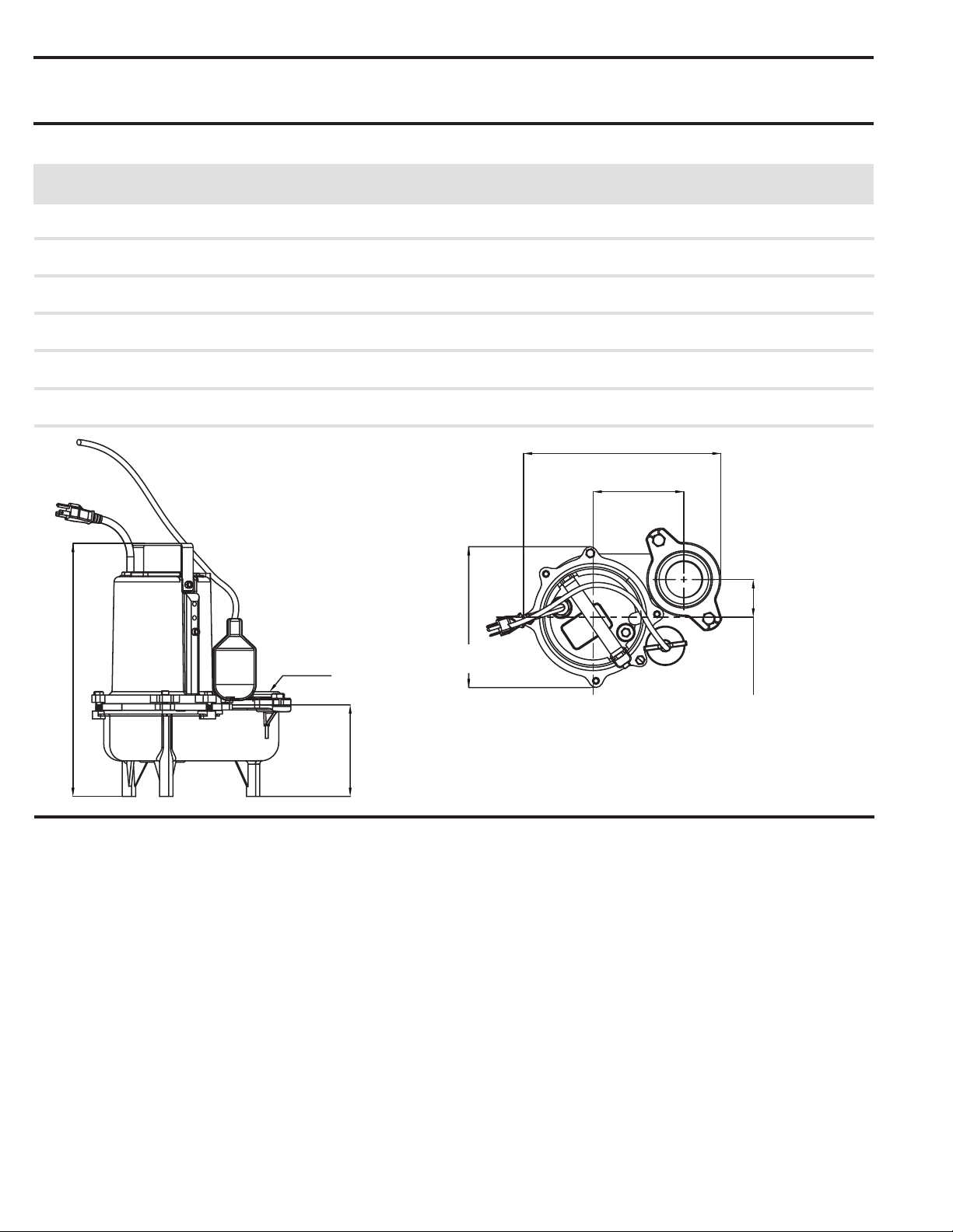
Note: All dimensions have a tolerance of + 1/8”
Overall Size (inches): 11.1 L x 8.35W x
15.0i n.
11.7i n.
8.35 in
5.37 in.
5.41 in.
11.7 in.
5.37 in.
8.35 in.
2.23 in.
15.0i n.
11.7i n.
8.35 in
5.37 in.
2.23 in.
5.41 in.
2” NPT Flanged Discharge,
3” NPT Optional
5.41 in.
15.0 in.

INSTALLATION
ELECTRICAL WIRE CONNECTION
OVERLOAD PROTECTION
Do not work on pump until
power is unplugged.
Do not cut off ground pin or
use an adapter tting.
Do not use an extension cord.
The pump power cord should be connected to a
separately fused, grounded line with a minimum
capacity of 15 amps. It can be connected to non-
fuse breaker at the recommended amperes.
1. Before installing or servicing this pump, be
certainpump’spowersourceisdisconnected.
2. Installation and electrical wiring must adhere
to state and local codes and must be
completed before priming pump. Check
appropriate community agencies, or contact
local electrical and pump professionals.
3. Call an electrician when in doubt. Pump
should be connected to a separate 15
amp circuit breaker or 15 amp fuse block.
Note that plugging into existing outlets may
cause low voltage at motor. This could cause
blown fuses, tripping of motor overload or
burned out motor.
4. A permanent ground connection from pump
to the grounding bar at the service panel is
mandatory. These sump pumps come with a
grounding conductor and a grounding-type
attachment plug. Do not connect pump to
a power supply until permanently grounded.
For maximum safety, connect pump to a circuit
equipped with a fault interrupter device when
positioningthepump’sgroundingwire.
5. Voltage of power supply must match the
voltage of the pump.
6. Before installing pump, clear sump basin of
any water, debris or sediment.
Sump basin must be vented
in accordance with local
plumbing codes. These Sump pumps are not
designed for and CANNOT be installed in loca-
tions classied as hazardous.
7. The following may cause injury and/or severe
damage to pump and will void the warranty.
(a) Using an extension cord.
(b) Cutting o the ground pin or using an
adapter tting.
(c) Working on pump or switch while
plugged in.
(d) Removing motor housing, unscrewing
impeller, or otherwise removing impeller seal.
(e) Running the pump continuously.
(f) Pumping chemicals or corrosive liquids.
(g)Pumpinggasolineorotherammableliquids
8. Plastic PVC pipe can be installed in the
outlet piping. Drain hose, galvanized steel
or copper pipe may be used if desired.
All piping must be clean and free of all
foreign matter to prevent clogging.
9. Pump will be inadequate if suspension
liquids contain solid particles larger than 2”.
Verify that the voltage and
frequency of the pump shown
on the nameplate corresponds to those available on
the mains. The installer must make sure that the
electric system is grounded in accordance with code.
• For outdoor use it is necessary to use cable with
alengthofatleast8’.Theplugandconnection
should be protected from water splashes. Before
using the pump, always inspect it visually
(especially power cable and plug)
• Do not use pump if it is damaged
• If the pump is damaged, have it inspected by an
authorized service center.
• Make sure that electric connections are protected
fromooding.Protecttheplugandthepower
cable from heat or sharp edges.
The power cable must be
replacedbyqualiedpersonnel
only. Grounding: The plug of the power cable has a
double grounding contact, so that grounding can be
performed by simply inserting the plug.
This pump series has a built in thermal protection
switch. The pump stops if an overload condition
occurs. The motor restarts automatically after it has
cooled down. If it doesn’t start automatically, unplug
the pump and plug it back in.
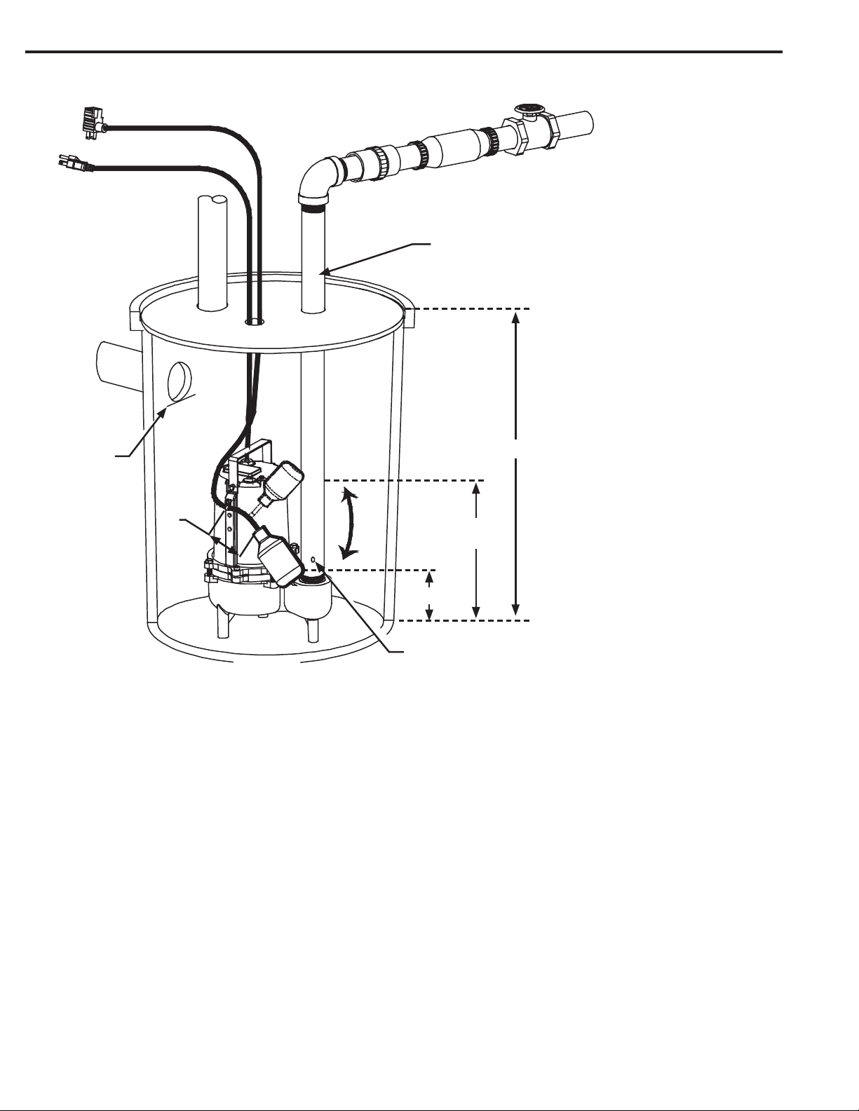
Entry pipe
3
INSTALLATION
When check valve is used, drill a relief hole 3/16”
in diameter in the discharge pipe. This hole
should be located below the oor line between
the pump discharge and the check valve. Unless
such a relief hole is provided, the pump could
“air-lock” and will not pump water even though it
will run.
A gate valve should follow the check valve to
allow periodic cleaning of the check valve or re-
moval of the pump.
The remainder of the discharge line should be
as short as possible with a minimum of turns to
minimize friction head loss. Do not restrict the
discharge to sizes below 2’.
Sewage and euent applications will require a
separate sump vent. A connection is provided on
top of the sump or cover which must be piped
to the existing building vent or extended outside
with its own standpipe.
A check valve must be used in
the discharge line to prevent
back ow of liquid into the ba-
sin. The check valve should be
a free ow valve that will easily
pass solids.
CAUTION: For best perfor-
mance of check valves when
handling solids install in a hor-
izontal position or at an angle
of not more then 45°. Do not
install check valve in a vertical
position as solids may settle
in valve and prevent opening
start-up.
For automatic operation, pump must be
plugged or wired into remote oat switch or
liquid level controller. Installation instructions in-
cluded with switches and controllers should be
referred to for installation.
Pump will run continuously if plugged directly
into an electrical outlet. Care should be taken to
prevent pump running in a dry sump.
Pump must be installed in a suitable gas tight
basin which is at least 24” in diameter and
30” deep and vented in accordance with local
plumbing codes. Pump must be placed on a
hard level surface. Never place pump directly on
clay, earth or gravel surfaces.
Pump can be installed with ABS, PVC, polyeth-
ylene or galvanized steel pipe. Proper adapters
are required to connect plastic pipe to pump.
Always install a union in the discharge line, just
above the sump pit to allow for easy removal of
the pump for cleaning or repair.
Min.30”
Approximate
15.5”
Approx. 7.5”
Switch OFF
Switch ON
3/16” O.D.
Air Bleed Hole
Discharge
Pipe
Gate Valve
Check Valve
Union
Piggyback Cord
Power Cord
Vent
Inlet
Pipe
Bottom of
Inlet Pipe
3.5”
Elbow
4

5
PROBLEMS
PUMP DOES NOT RUN
AND MAKES HUMMING
SOUND
PUMP RUNS BUT DOES
NOT DELIVER WATER
PUMP RUNS AND
PUMPS
OUT SUMP, BUT DOES
NOT STOP
PUMP RUNS BUT ONLY
DELIVERS A SMALL
AMOUNT OF WATER
FUSE BLOWS OR
CIRCUIT BREAKER
TRIPS WHEN
PUMP STARTS
MOTOR RUNS FOR A
SHORT TIME, THEN
STOPS
POSSIBLE CAUSES/SOLUTIONS
• Line circuit breaker is o, or fuse is blown or loose
• Water level in sump has not reached turn-on level as indicated in
installation drawing.
• Pump cord is not making contact in receptacle.
• Float is stuck. It should operate freely in basin.
• If all of the above are OK, then the motor could be malfunctioning.
• Check if valve is installed backwards.
Arrow on valve should point direction of ow
• Discharge shut-o valve (if used) may be closed.
• Impeller or volute openings are fully or partially clogged.
Remove pump and clean.
• Pump is air-locked. Start and stop several times by plugging and
unplugging cord. Check for clogged vent hole in pump case.
• Inlet holes in pump base are clogged. Remove pump and clean the
openings.
• Vertical pumping distance is too high. Reduce distance or change the
discharge ttings of the pump.
• Float is stuck in up position. Be sure oat operates freely in basin.
• Defective oat switch. Replace oat switch.
• Pump is air-locked. Start and stop several times by plugging in and
unplugging cord. Check for clogged vent hole in pump case.
• Vertical pumping distance is too high. Reduce distance or change the
discharge tting of the pump. Inlet holes in pump base are clogged.
Remove pump and clean the strainer and openings.
• Impeller or volute openings are fully or partially clogged.
Remove pump and clean.
• Pump impeller is partially clogged with tar or paint, causing motor to
run slow and overload. Remove pump and clean.
• Pump impeller is partially clogged causing motor to run slow and
overload. Remove pump and clean.
• Motor stator may be defective.
• Fuse size or circuit breaker may be too small. (must be 15 amps).
• Impeller or volute opening are fully or partially clogged.
Remove pump and clean .
• Inlet holes in pump base are clogged. Remove pump and clean the
openings.
• Pump impeller is partially clogged causing motor to run slow and
overload. Remove pump and clean.
• Motor stator may be defective.
• Impeller or volute openings are fully or partially clogged.
Remove pump and clean. Also clean the strainer if one is installed.
ELECTRICAL PRECAUTIONS
Before servicing a pump, always shut o the main power breaker and
then unplug the pump. Make sure you are not standing in water and are
wearing insulated protective sole shoes, under ooded conditions. Contact your local electric
company or a qualied licensed electrician for disconnecting electrical service prior to pump
removal
TROUBLE SHOOTING CHECKLIST (Caution: shut off power to pump)

LIMITED WARRANTY
Retain Original Purchase Receipt for Warranty Eligibility
Manufacturer warrants to the original consumer purchaser (“Purchaser” or “You”) that its products are free from defects
in material and workmanship for a period of twenty-four (24) months from the date of the original consumer purchase. If,
within twenty-four (24) months from the original consumer purchase, any such product shall prove to be defective, it shall
berepairedorreplacedatmanufacturer’soption,subjecttothetermsandconditionssetforthherein.Notethatthislimited
warranty applies to manufacturing defects only and not to ordinary wear and tear. All mechanical devices need periodic
parts and service to perform well. This limited warranty does not cover repair when normal use has exhausted the life of a
part or the equipment.
The original purchase receipt and product warranty information label are required to determine warranty eligibility. Eligibil-
ity is based on purchase date or original product – not the date of replacement under warranty. The warranty is limited to
repair or replacement of original purchased product only, not replacement product (i.e. one warranty replacement allowed
per purchase).
Purchaser pays all removal, installation, labor, shipping, and incidental charges.
Claims made under this warranty shall be made by returning the product to the retail outlet where it was purchased or to
the factory immediately after the discovery or any alleged defect. Manufacturer will subsequently take corrective action as
promptly as reasonably possible. No requests for service will be accepted if received more than 30 days after the warranty
expires. Warranty is not transferable and does not apply to products used in commercial/rental applications.
General Terms and Conditions; Limitations of Remedies
You must pay all labor and shipping charges necessary to replace product covered by this warranty. This warranty does
notapplytothefollowing:(1)actsofGod;(2)productswhich,inmanufacturer’ssolejudgment,havebeensubjectto
negligence, abuse, accident, misapplication, tampering, or alteration; (3) failures due to improper installation, operation,
maintenance or storage; (4) atypical or unapproved application, use or service; (5) failures caused by corrosion, rust or
other foreign materials in the system, or operation at pressures in excess of recommended maximums.
Thiswarrantysetsforthmanufacturer’ssoleobligationandpurchaser’sexclusiveremedyfordefectiveproducts.
MANUFACTURER SHALL NOT BE LIABLE FOR ANY CONSEQUENTIAL, INCIDENTAL, OR CONTINGENT DAMAGES
WHATSOEVER. THE FOREGOING LIMITED WARRANTIES ARE EXCLUSIVE AND IN LIEU OF ALL OTHER EXPRESS
AND IMPLIED WARRANTIES, INCLUDING BUT NOT LIMITED TO IMPLIED WARRANTIES OF MERCHANTABILITY
AND FITNESS FOR A PARTICULAR PURPOSE. THE FOREGOING LIMITED WARRANTIES SHALL NOT EXTEND
BEYOND THE DURATION PROVIDED HEREIN.
Some states do not allow the exclusion or limitation of incidental or consequential damages or limitations on how long an
impliedwarrantylasts,sotheabovelimitationsorexclusionsmaynotapplytoYou.ThiswarrantygivesYouspeciclegal
rights and You may also have other rights which vary from state to state.
6
1899 Cottage Street
Ashland, Ohio 44805
Telephone: 1-844-394-2604