
P/NO : MFL50024813
www.lg.com
INSTALLATION MANUAL
AHU COMMUNICATION KIT
• Please read this installation manual completely before installing the product.
• Installation work must be performed in accordance with the national wiring
standards by authorized personnel only.
• Please retain this installation manual for future reference after reading it
thoroughly.
MODEL : PRDCAM
ENGLISH
FRANÇAIS
ESPAÑOL

TIPS FOR SAVING ENERGY
2
ENGLISH
• Do not cool excessively indoors. This may be harmful for your health and may consume more
electricity.
• Block sunlight with blinds or curtains while you are operating the equipment.
• Keep doors or windows closed tightly while you are operating the equipment.
• Adjust the direction of the air flow vertically or horizontally to circulate indoor air.
• Speed up the fan to cool or warm indoor air quickly, in a short period of time.
For your records
Staple your receipt to this page in case you need it to prove the date of purchase or for warranty
purposes. Write the model number and the serial number here:
Model number :
Serial number :
You can find them on a label on the side of each unit.
Dealer’s name :
Date of purchase :
Here are some tips that will help you minimize the power consumption when you use the air
conditioner. You can use your equipment more efficiently by referring to the instructions
below:
TIPS FOR SAVING ENERGY

3
IMPORTANT SAFETY INSTRUCTIONS
ENGLISH
IMPORTANT SAFETY INSTRUCTIONS
READ ALL INSTRUCTIONS BEFORE USING THE APPLIANCE.
Always comply with the following precautions to avoid dangerous situations and ensure peak
performance of your product
WARNING
It can result in serious injury or death when the directions are ignored
CAUTION
It can result in minor injury or product damage when the directions are ignored
WARNING
• Installation or repairs made by unqualified persons can result in hazards to you and others.
• Installation MUST conform with local building codes or, in the absence of local codes, with
the Nation Electrical Code NFPA 70/ANSI C1-1003 or current edition and Canadian Electrical
Code Part1 CSA C.22.1.
• The information contained in the manual is intended to use by a qualified service technician
familiar with safety procedures and equipped with the proper tools and test instruments.
• Failure to carefully read and follow all instructions in this manual can result in equipment mal-
function, property damage, personal injury and/or death.
Installation
• Always perform grounding.
- Otherwise, it may cause electrical shock.
• Don’t use a power cord, a plug or a loose socket that is damaged.
- Otherwise, it may cause fire or electrical shock.
• For installation of the product, always contact the service center or a professional installation
agency.
- Otherwise, it may cause fire, electrical shock, explosion or injury.
• Securely attach the electrical part cover to AHU Comm. Kit.
- If the electric part cover of AHU Comm. Kit is not attached securely, it could result in a fire or
electric shock due to dust, water, etc.
• Always install an air leakage breaker and a dedicated switching board.
- No installation may cause a fire and electrical shock.
• Do not keep or use flammable gases or combustibles near the equipment.
- Otherwise, it may cause a fire or the failure of product.
• Do not install, remove or reinstall the unit by yourself.
- Otherwise, it may cause a fire, electrical shock, explosion or injury.
• Do not disassemble or repair the product randomly.
- It will cause a fire or electrical shock.
• Do not install the product in a place where there is the concern of falling down.
- Otherwise, it may result in personal injury.
• Use caution when unpacking and installing.
- Sharp edges may cause injury.
!
!
!

IMPORTANT SAFETY INSTRUCTIONS
4
ENGLISH
Operation
• Do not share the outlet with other appliances.
- It will cause an electric shock or a fire due to heat generation.
• Do not use the damaged power cord.
- Otherwise, it may cause a fire or electrical shock.
• Do not modify or extend the power cord randomly.
- Otherwise, it may cause a fire or electrical shock.
• Take care so that the power cord may not be pulled during operation.
- Otherwise, it may cause a fire or electrical shock.
• Unplug the unit if strange sounds, smell, or smoke comes from it.
- Otherwise, it may cause electrical shock or a fire.
• Keep flames away.
- Otherwise, may occur a fire.
• Take the power plug out if necessary, holding the head of the plug and do not touch it with
wet hands.
- Otherwise, it may cause a fire or electrical shock.
• Do not use the power cord near the heating tools.
- Otherwise, it may cause a fire and electrical shock.
• Do not allow water to run into electrical parts.
- Otherwise, it may cause the failure of machine or electrical shock.
• Hold the plug by the head when taking it out.
- It may cause electric shock and damage.
• Be cautious that water could not enter the product.
- Otherwise, it may cause a fire electrical shock or product damage.
• Do not step on the indoor/outdoor unit and do not put anything on it.
- It may cause an injury through dropping of the unit or falling down.
• Do not place a heavy object on the power cord.
- Otherwise, it may cause a fire or electrical shock.
• When the product is submerged into water, always contact the service center.
- Otherwise, it may cause a fire or electrical shock.

5
2 TIPS FOR SAVING
ENERGY
3 IMPORTANT SAFETY
INSTRUCTIONS
6 INSTALLATION SCENE
7 SUPPLIES
8 OPTIONAL
9 PART DESCRIPTION
9 Communication Kit (PRDCAM)
10 BEFORE INSTALLATION
13 COMMUNICATION KIT
INSTALLATION
13 Mechanical installation
15 Electric Wiring Work
17 Electrical Work
18 Controller Setting Method
23 AHU KIT WIRING CON-
FIGURATION WITH DDC
23 Configuration concept
24 DI Wring concept
25 DO Wring concept
26 AI Wring concept
28 FAN Signal Wiring Concept
29 THERMISTORS INSTAL-
LATION
29 Pipe thermistors Installation
32 TROUBLESHOOTING
TABLE OF CONTENTS
TABLE OF CONTENTS
ENGLISH
6
INSTALLATION SCENE
ENGLISH
Signal
Pipe
Thermistor
4
10
6
8
9
7
2
5
1
Field supply
DDC
Air flow
3
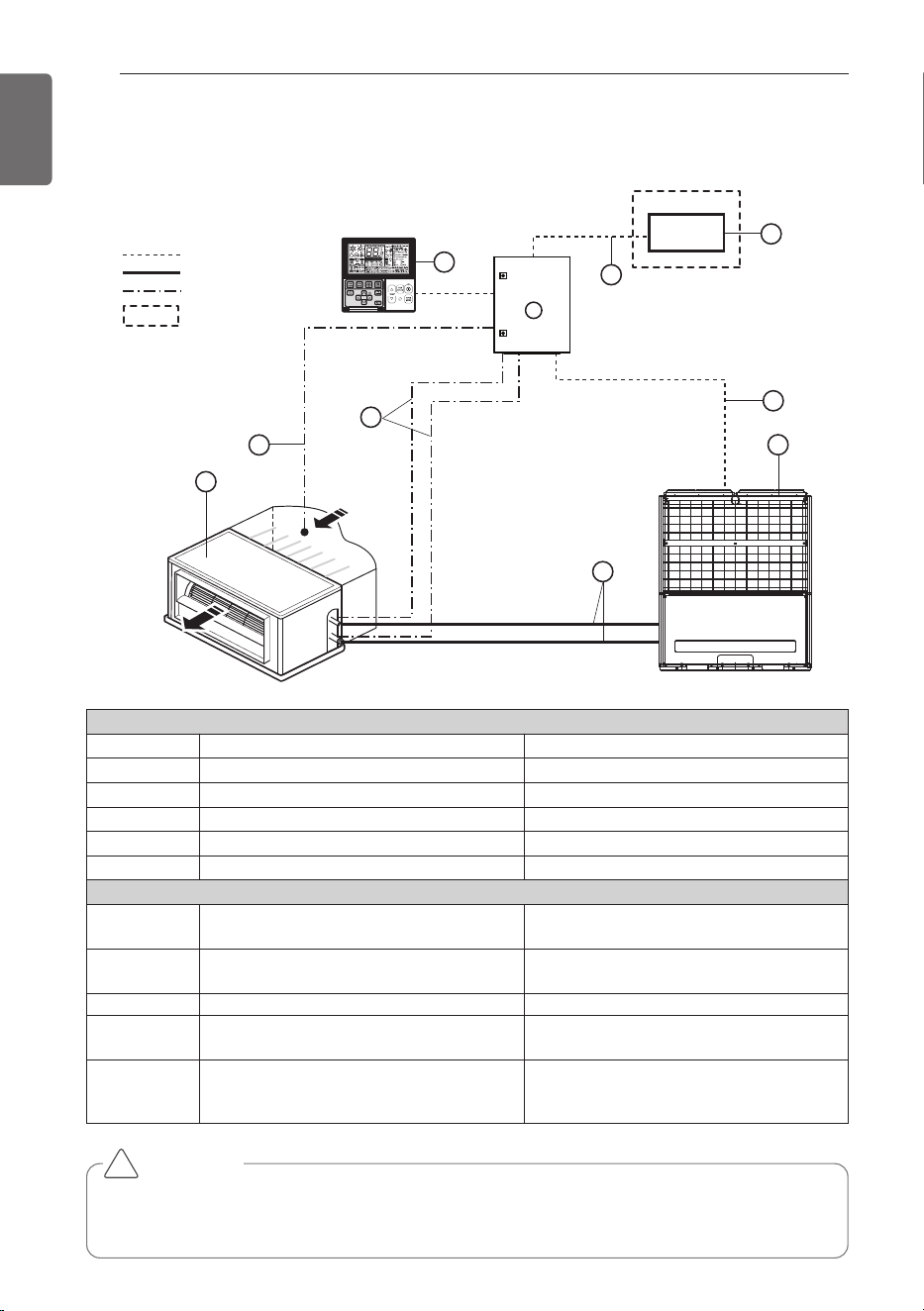
INSTALLATION SCENE
Parts and components
No. Name Remarks
1 AHU Field supply
2 Outdoor Unit Multi V
3 AHU Communication Kit(PRDCAM) -
4 DDC Field supply(Central control Device)
5 Field piping Field supply
Wiring connections
6 Communication Kit Wiring
Power supply and communication
between comm. kit and outdoor unit
7
Pipe thermistors
(EBG62485902/EBG62485903)
Evaporator (In/Out) control of AHU
8 Room thermistor (EBG62485901) Return air control
9
Remote controller
(PQRCVSL0 / PQRCVSL0QW)
Optional
10 Signal
• Fan signal(Low / Middle / High)
• Defrost / Heating / Cooling signal
• Themal On/Off
CAUTION
For Installation of Room thermistor (No. 8), always place it at the inlet of Heat Exchanger.
Otherwise, it might not operate properly.
!
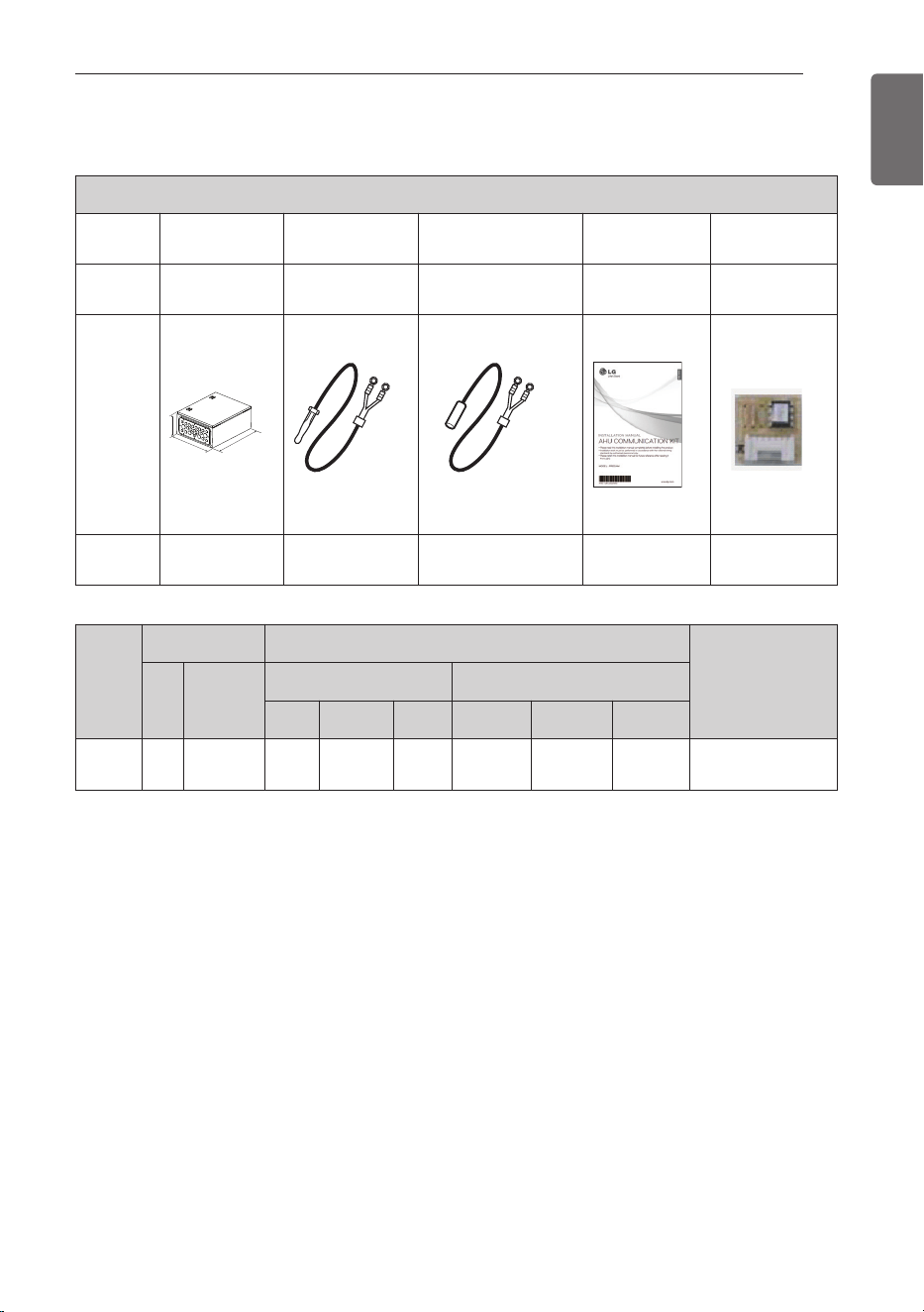
SUPPLIES
7
ENGLISH
PRDCAM
Compo-
nents
AHU Comm.
Kit
Room
thermistor
Pipe
thermistors
Installation
Manual
Option PCB
P/NO
AJT74775302 EBG62485901
EBG62485902(In)
EBG62485903(Out)
MFL50024813
EBR52358907
~17
Shape
W
H
D
Quantity
(EA)
1 1 2(Each 1) 1 11(Each 1)
Model
Name
Weight [kg (lb)]
Dimension [mm (inch)]
POWER
NET Gross
NET Gross
W H D W H D
PRDCAM
13.6
(30)
15.2
(33.5)
400
(15-3/4)
500
(19-11/16)
210
(8-9/32)
466
(18-11/32)
569
(22-13/32)
274
(10-25/32)
208/230 V ~ 60 Hz
SUPPLIES
8
OPTIONAL
ENGLISH
* For further details of the accessories, refer to the manual provided at the time of purchasing
the accessories.
Accessories
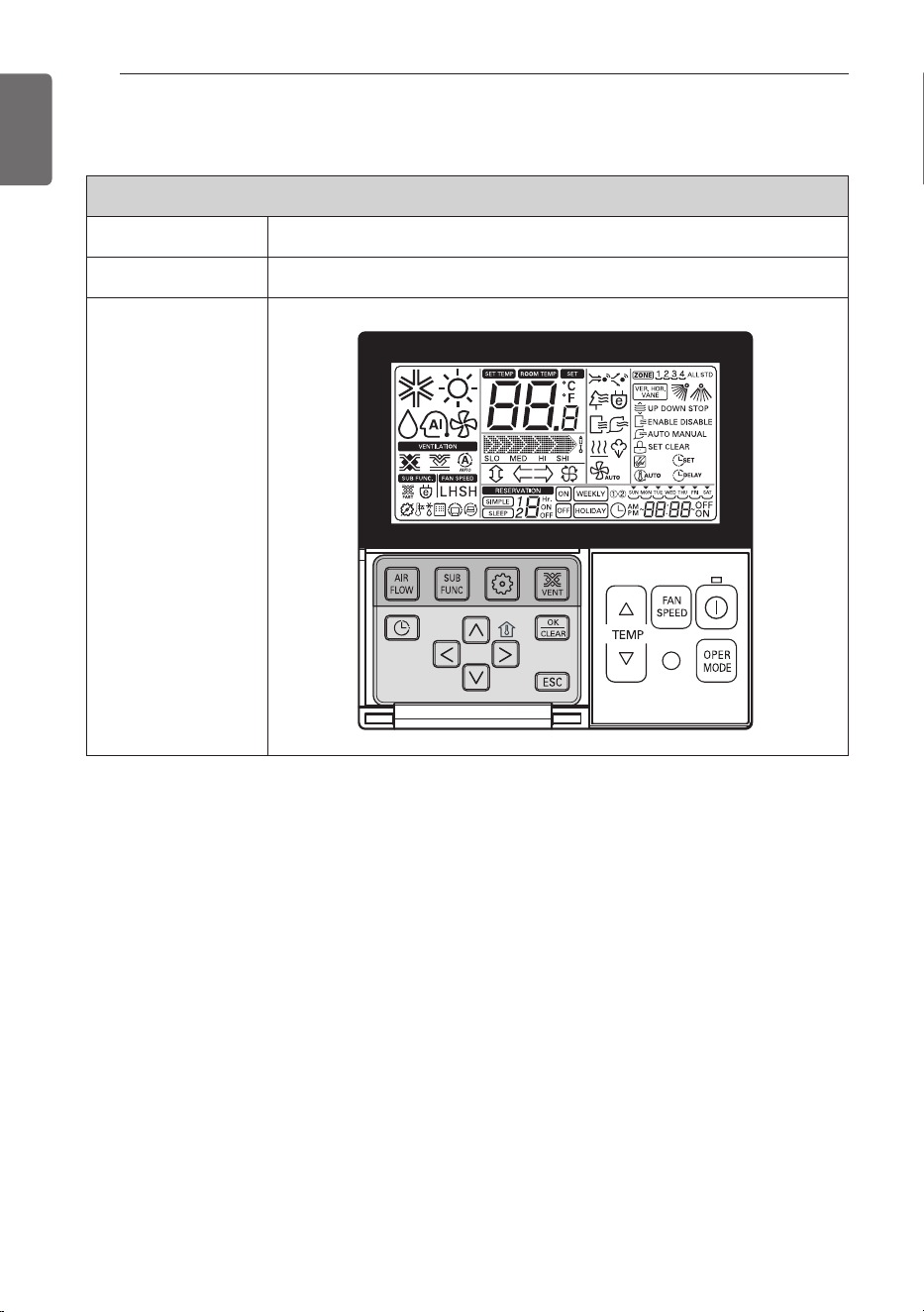
Components Remote controller
Model name PQRCVSL0 / PQRCVSL0QW
Shape
OPTIONAL
PART DESCRIPTION
9
ENGLISH
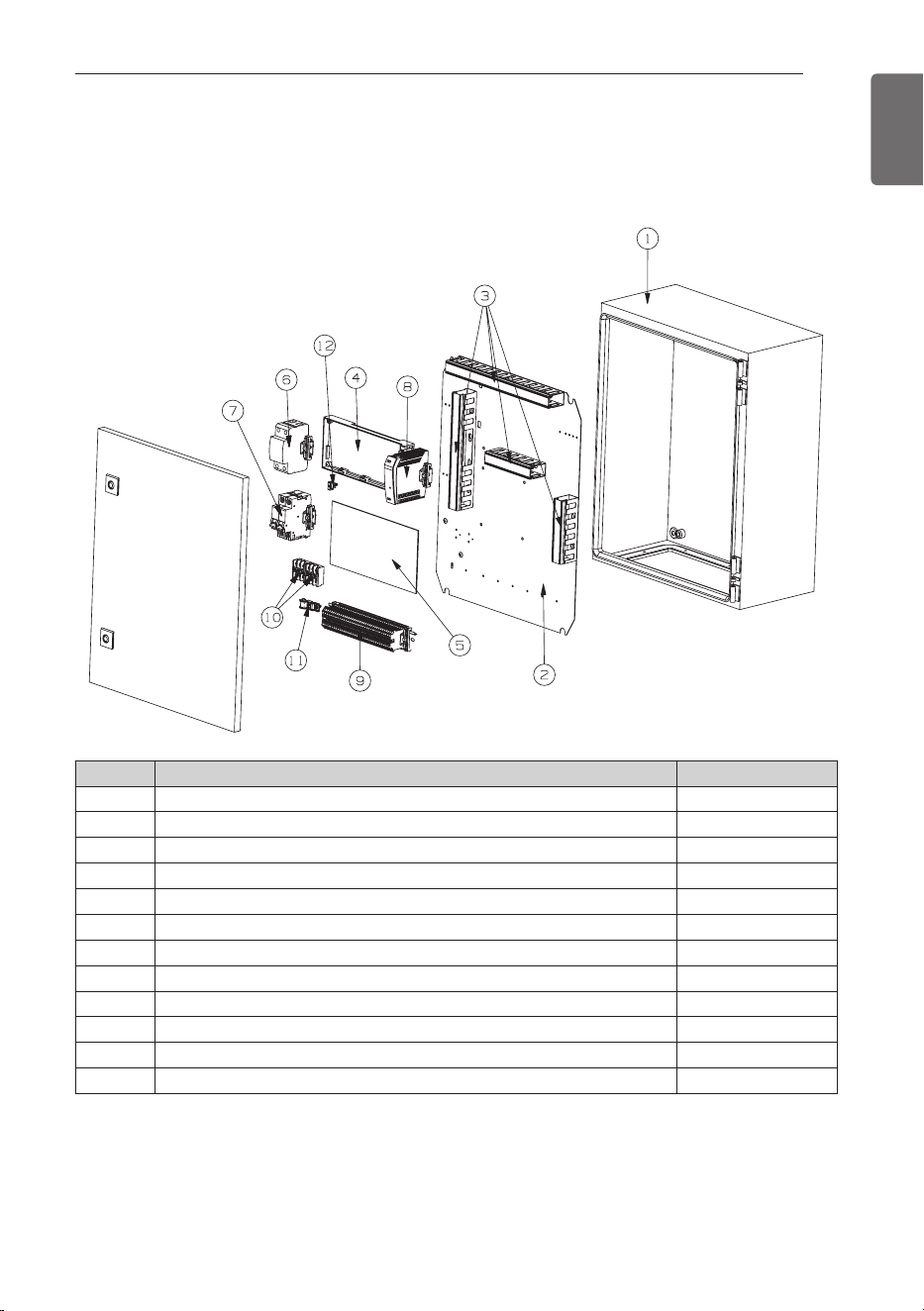
Communication Kit (PRDCAM)
No. m Part Name Quantity (EA)
1 Case,Control (Indoor) 1
2 Panel,Control 1
3 DUCT 4
4 PCB Assembly,Main 1
5 PCB Assembly,Main (I/O PCB) 1
6 Surge Protector 1
7 Brake, wire 1
8 SMPS 1
9 Connector,Terminal Block 1
10 Connector,Terminal Block 2
11 Clamp,Cord 1
12 Supporter 1
PART DESCRIPTION
10
BEFORE INSTALLATION
ENGLISH
CAUTION
• Don't install or operate the unit in rooms mentioned below.
① Where mineral oil, like cutting oil is present.
② Where the air contains high levels of salt such as air near the ocean.
③ Where sulphurous gas is present such as that in areas of hot spring.
④ In vehicles or vessels.
⑤ Where voltage fluctuates a lot such as that in factories.
⑥ Where high concentration of vapor spray are present.
⑦ Where machines generating electromagnetic waves are present.
⑧ Where acidic or alkaline vapor is present.
⑨ The option boxes must be installed with entrances downward.
• Check the mentioned below, when you apply the AHU (Field supply).
① If the AHU (Field supply) provided in the field is exclusively for heating, you must not
change the operating mode to cooling on the remote controller. If not, it can cause
electric shock, injury or death. If you want to operate in cooling mode, AHU (Field sup-
ply) must comply with the following details.
(Following)
- The insulation level of AHU (Field supply) motor must be ‘F’ or above, and the protec-
tion level must satisfy ‘IP 54’.
- AHU (Field supply) must have the drain pan installed.
② Fan speed button on the wired remote controller (PQRCVSL0 / PQRCVSL0QW) is not
operated.
③ For refrigerant piping of outdoor unit, refer to the installation manual supplied with the
outdoor unit.
④ For installation of the wired remote controller (PQRCVSL0 / PQRCVSL0QW), refer to
the manual supplied with the wired remote controller.
⑤ For protecting the refrigerant cycle in heating, the inlet Air temperature to the Heat
Exchanger has to be over 5 °C (41 °F).
⑥ The EEV or TXV kit has to be installed on the AHU as close as possible to the Heat
Exchanger.
• AHU Communication Kit
① Thermistor cable and remote controller wire should be located at least 50 mm away
from power supply wires and from wires to the controller. Not following this guideline
may result in malfunction due to electrical noise.
② Use only specified wires, and tightly connect wires to the terminals. Keep wiring in
neat order so that it does not obstruct other equipment. Incomplete connections could
result in overheating, and in worse case electric shock or fire.
!
BEFORE INSTALLATION
BEFORE INSTALLATION
11
ENGLISH
CAUTION
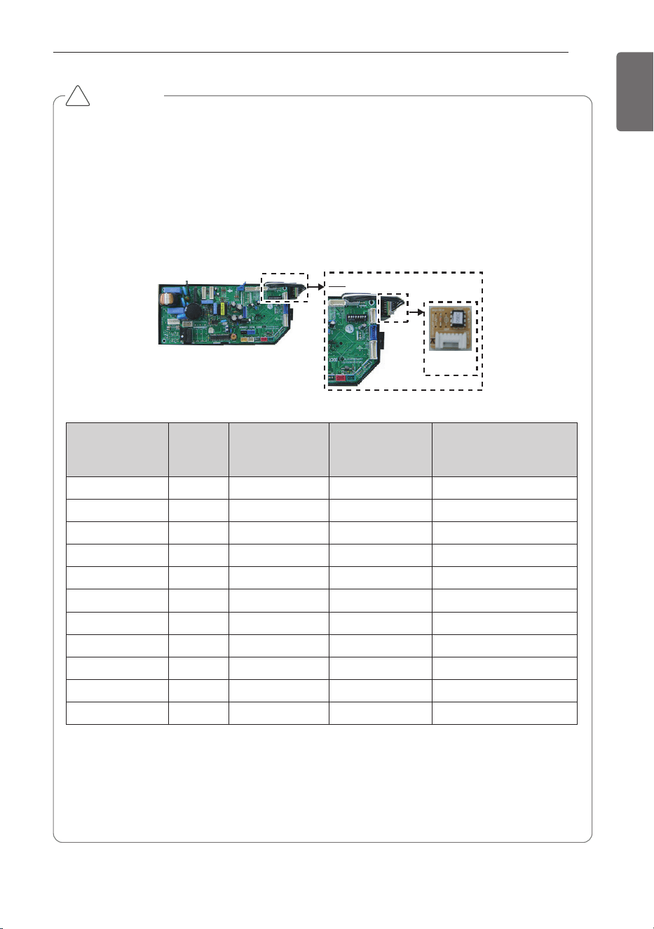
Selection of Evaporator(Air Handling Unit)
See table below for applicable units
Selecting the capacity setting 'Option PCB'(Accessory) according to the capacity mentioned
below.
- The corresponding capacity setting 'Option PCB' needs to be selected depending on the
need capacity.
- After checking the need capacity, remove the 192 k Option PCB equipped in the main
PCB, and set up the Option PCB fitted the need capacity in the main PCB.
* Evaporator Saturated Temperature(SST) = 6 °C (42.8 °F), SH (Superheat) 5K, Air Tempera-
ture = 27 °C (80.6 °F) DBT / 19 °C (66.2 °F) WBT
* Heat exchanger volume [m
3
(ft
3
)] : Pipe cross-section × Tube length
-. Pipe cross-section [m
2
(ft
2
)] = π × ID
2
/4
-. Tube length [m(ft)] = Tube length of 1 pipe × Tube step × Tube row
!
Capacity setting
'Option PCB'
Detail
Option PCB
P/NO
Capacity
(Btu/h)
Standard heat
exchanger volume
[10
-3
× m
3
(ft
3
)]
Maximum heat
exchanger capaci-
ty [kw (kBtu/h)]
Air Flow rate
[CMM (CFM)]
EBR52358907 28 k 2.7 (95.3) 8.6 (29.3) 22 (777)~26 (919)
EBR52358908 36 k 3.1 (109.5) 11 (37.5) 25 (883)~32 (1,131)
EBR52358909 42 k 3.4 (120) 13.8 (47.1) 31 (1,095)~35 (1,237)
EBR52358910 48 k 4.0 (141.3) 15.4 (52.5) 33 (1,166)~45 (1,590)
EBR52358911 76 k 5.4 (190.7) 22.2 (75.7) 50 (1,767)~64 (2,261)
EBR52358912 96 k 6.3 (222.5) 28.1 (95.9) 64 (2,261)~72 (2,544)
EBR52358914 115 k 7.3 (257.8) 33.7 (115) 72 (2,544)~88 (3,110)
EBR52358915 134 k 8.5 (300.2) 39.3 (134.1) 88 (3,110)~103 (3,640)
EBR52358916 153 k 9.5 (335.5) 45.4 (154.9) 103 (3,640)~116 (4,099)
EBR52358917 172 k 10.5 (370.8) 50.4 (172) 114 (4,028)~129 (4,558)
EBR52358913 192 k 11.2 (395.5) 56.2 (191.8) 121 (4,276)~137 (4,841)

12
BEFORE INSTALLATION
ENGLISH
CAUTION
• AHU Operation range
- When installing Room thermistor, always place it to the inlet of Heat Exchanger. Other-
wise, it may might not operate properly.
- Range of the inlet Air temperature to the Heat Exchanger is 18~40 °C (64.4~104 °F) for
cooling & 5~30 °C (41~86 °F) for heating. If the temperature is under 18 °C (64.4 °F) for
cooling & over 30 °C (86 °F) for heating, the system might operate ON and OFF because
of protection logic system’s.
!
No Connection condition Combination
1
100% Fresh Air Intake
AHU only are connected
with outdoor units
1) The total capacity of 100% Fresh Air Intake AHU should be
50~100% of outdoor unit.
COMMUNICATION KIT INSTALLATION
13
ENGLISH
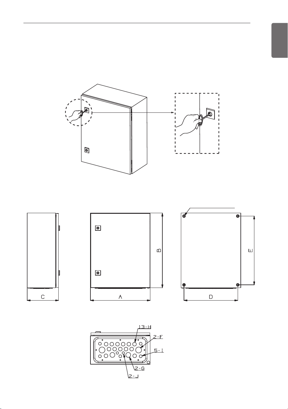
Mechanical installation
1 Open the door using the key.
COMMUNICATION KIT INSTALLATION
2 Drill 4 holes on correct position and fix the Comm. Kit box securely with 4 screws
(Field supply) through the holes Ø9mm(11/32 inch) [Reference the length of the holes
Ø9(11/32)]
<Side> <Front side>
<Bottom side>
<Back side>
4- Ø9(11/32) HOLES
14
COMMUNICATION KIT INSTALLATION
ENGLISH
Spec Remark
Size
[mm (inch)]
A 400 (15-3/4) Width
B 500 (19-11/16) Height
C 210 (8-9/32) Depth
D 360 (14-3/16)
AHU locking hole
E 460 (18-1/8)
F Ø40 (1-9/16) Power/airflow cable insertion part
G Ø33 (1-5/16) -
H Ø25 (31/32) Sensor/communication line cable insertion part
I Ø20 (25/32) -
J Ø17 (21/32) -
Weight
[kg (lb)]
Product 13.6 (30) Product weight
Packaging 15.2 (33.5) Weight after packing
WARNING
!
• Install where it can sufficiently support the weight of the comm.Kit.
If the support strength is not enough, the outdoor unit may drop and hurt people.
• Install where the comm.kit may not fall in strong wind or earthquake.
If there is a fault in the supporting conditions, the comm.kit may fall and hurt people.
• It is installed at a place with a lot of snowfall, install with the place higher than the most
extreme snowfall amount standard.
COMMUNICATION KIT INSTALLATION
15
ENGLISH
CAUTION
If you want to use Analogue Input signal for a variable capacity and a set temperature of
room, you have to connect the wiring of AI 10-2, AI 10-3, AI 10-4.
!
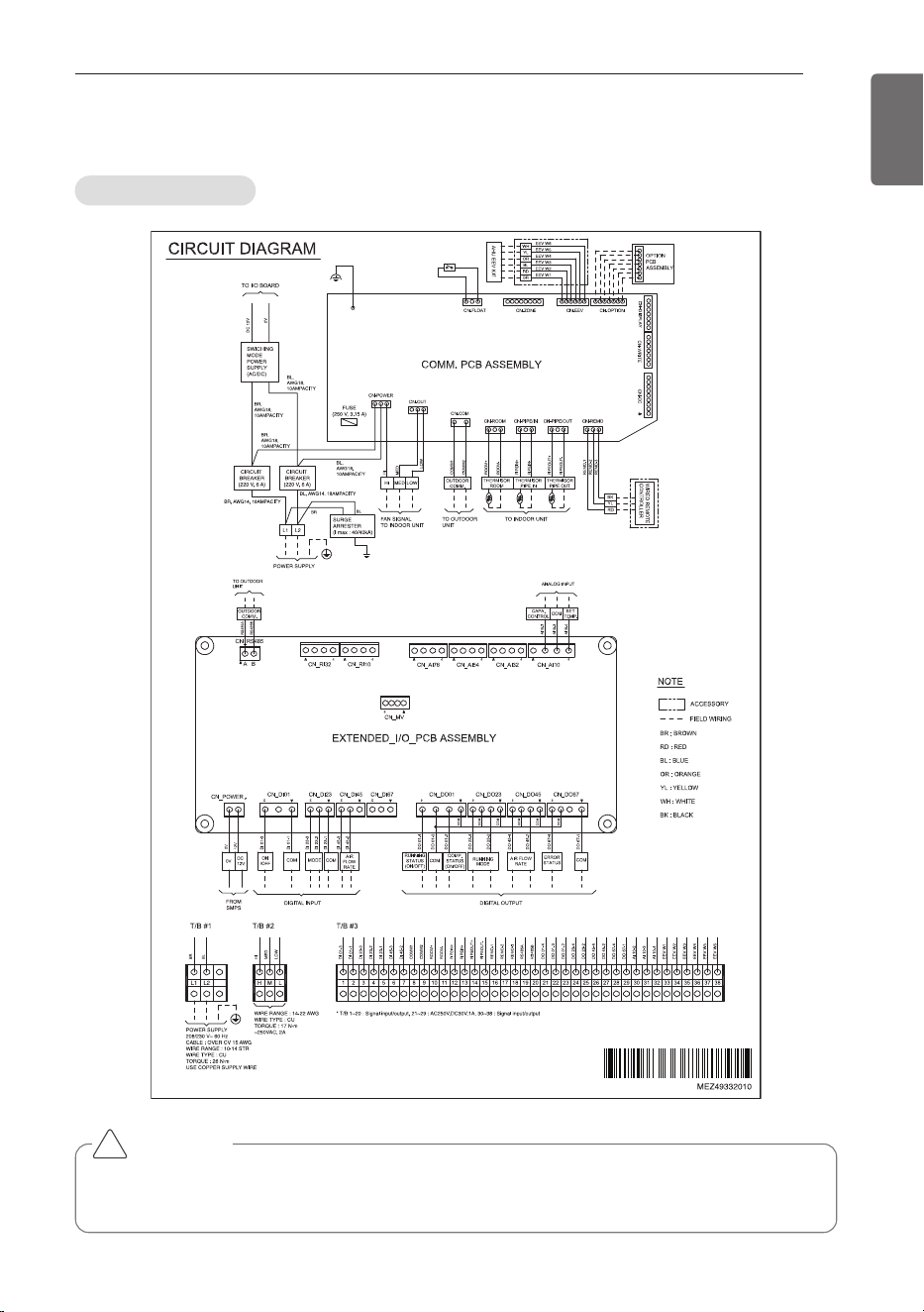
Circuit diagram
Electric Wiring Work
16
COMMUNICATION KIT INSTALLATION
ENGLISH
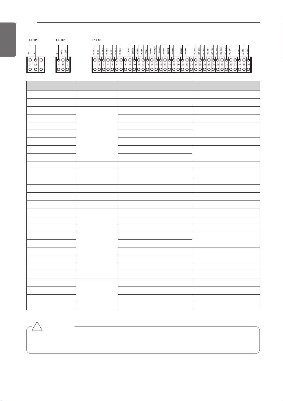
Terminal Block No. Connection Function Remark.
L1 / L2 Power supply 208 / 230 V, 60Hz, 1Phase -
H / M / L Fan signal Change Air flow rate -
1
Digital input
DI 01-3 Operation ON/OFF
2 DI 01-1 Common Line
3 DI 23-3
Mode change
4 DI 23-2
5 DI 23-1 Common Line
6 DI 45-3
Air flow rate
7 DI 45-2
8 ~ 9 To outdoor unit Communication Line -
10 ~ 11
To indoor unit (AHU)
Room thermistor -
12 ~ 13 Pipe in thermistor -
14 ~ 15 Pipe out thermistor -
16 ~ 18 Remote controller -
19 ~ 20
To outdoor unit
RS485 communication -
21
Digital output
DO 01-4
Running status (ON/OFF)
22 DO 01-3 Common line
23 DO 01-2 Comp. status (ON/OFF)
24 DO 23-4
Running mode
25 DO 23-2
26 DO 45-4
Air flow rate
27 DO 45-2
28 DO 67-4
Error status
29 DO 67-1 Common line
30
Analog input
AI 10-2 Capacity control
31 AI 10-3 Common line
32 AI 10-4 Room Temperature setting
33 ~ 38
To EEV Kit
EEV Kit -
CAUTION
If you want to use Analogue Input signal for a variable capacity and a set temperature of
room, you have to connect the wiring of AI 10-2, AI 10-3, AI 10-4.
!
COMMUNICATION KIT INSTALLATION
17
ENGLISH
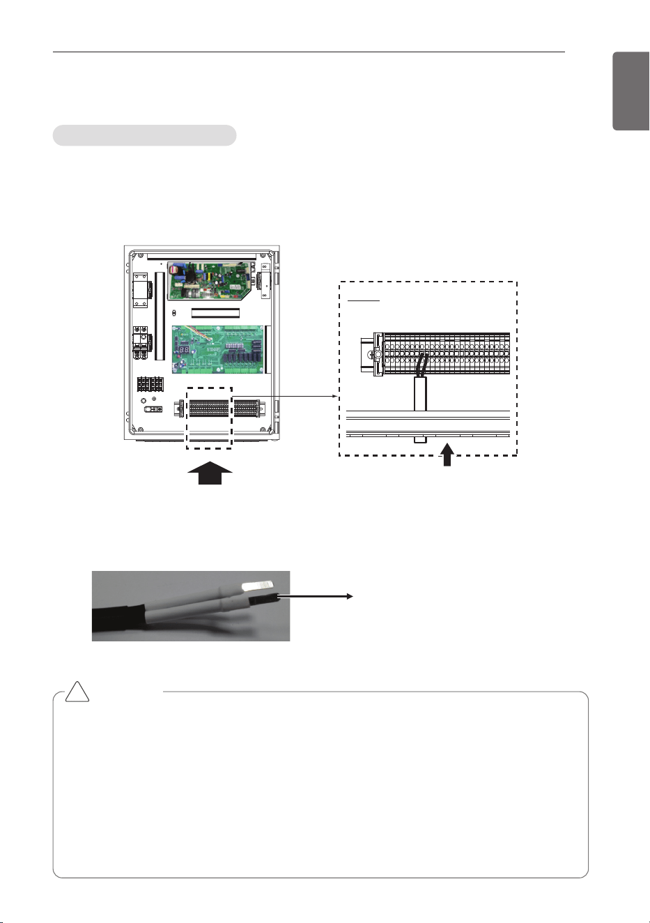
1 For connection to outdoor unit and to controller (Field supply) :
Pull the wires inside through the cable gland and close the nut firmly in order to ensure a
good pull relieve and water protection.
2 The wires require an additional pull-relief. Strap the wire with the support tie wrap.
3 For the wired remote controller wire and outdoor unit communication wire, remove the
coating at the end of the wire to connect and use the Pin type (JOBN153) to connect to the
terminal block.
(Side view)
(Front view)
Cable Insert
Detail
Pin type (JOBN153)
Connection of the wires
Electrical Work
CAUTION
• All field supplied parts and materials and electric works must be conform to local codes.
• Use copper wire only.
• All wiring must be performed by an authorized electrician.
• A main switch or other means for disconnection, having a contact separation in all poles,
must be incorporated in the fixed wiring in accordance to relevant local and national legisla-
tion.
• Refer to the installation manual attached to the outdoor unit for the size of power supply
electric wire connected to the outdoor unit, the capacity of the circuit breaker and switch,
wiring and wiring instructions.
!
18
COMMUNICATION KIT INSTALLATION
ENGLISH
CAUTION
- DI requires non-voltage contact
- DO provides relay output (max : 250Vac 1A)
- AI : 0Vdc ~ 10Vdc
- RS485 port : Connect to INTERNET A/B on ODU’s main PCB
!
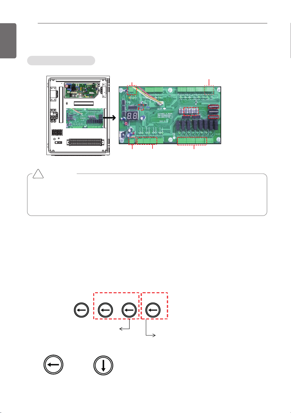
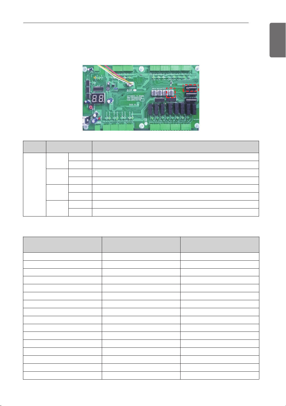
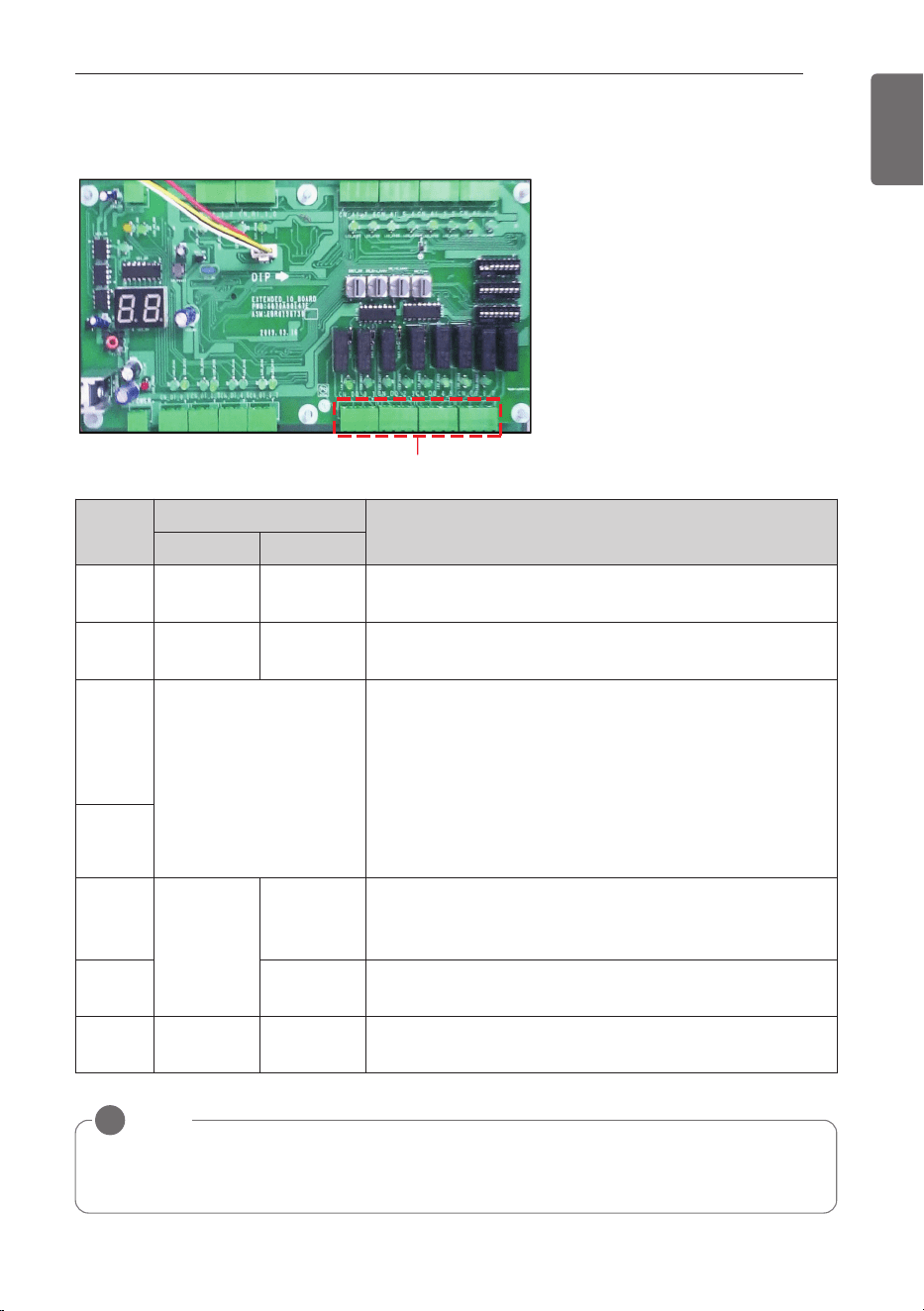
ڸ
ڹ
ں
DIP S/W(SW03)
DIP S/W(SW01)
Communication port
(1ch, RS485)
Analog Input(2ch)
Power(DC 12V)
Digital Input(5ch)
Digital Output(7ch)
Rotary S/W
Reset
Button
(3EA)
1 Analog Input : Control the supply air temperature and Comp. capacity of MULTI_V.
2 Digital Input : Acquires the control value of AHU operation from DDC (Field supply).
3 Digital Output : Send the condition value of AHU operation to DDC (Field supply).
4 RS485 : Sends the On/Off signal taking from DDC to the indoor & outdoor unit and send the
condition value taking from indoor & outdoor unit to DDC with On/Off Output.
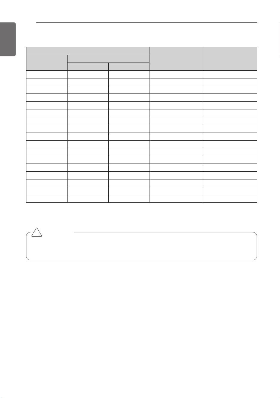
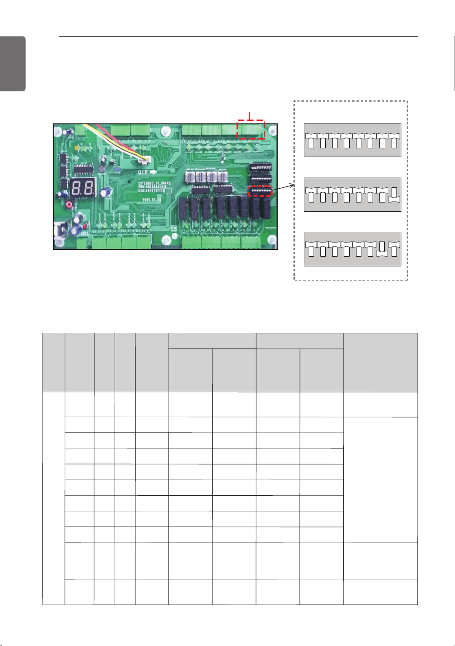
SW_SPARE
SW_GRP
SW_IO
SW_TYPE
This S/W is for setting up the address of
AHU Comm. Kit (00 ~ FF).
This S/W is for setting up the
temperature from AHU Comm. Kit.
Detail information refer to the
ڻ Room Temperature control from DDC or Rotary S/W
Example) AHU Comm. Kit address is ‘0C’ .
SW_GRP
SW_IO
0
C
0
1
2
3
4
5
6
7
8
9
A
B
C
D
E
F
0
1
2
3
4
5
6
7
8
9
A
B
C
D
E
F
① Rotary S/W
Capacity controller
Controller Setting Method
COMMUNICATION KIT INSTALLATION
19
ENGLISH
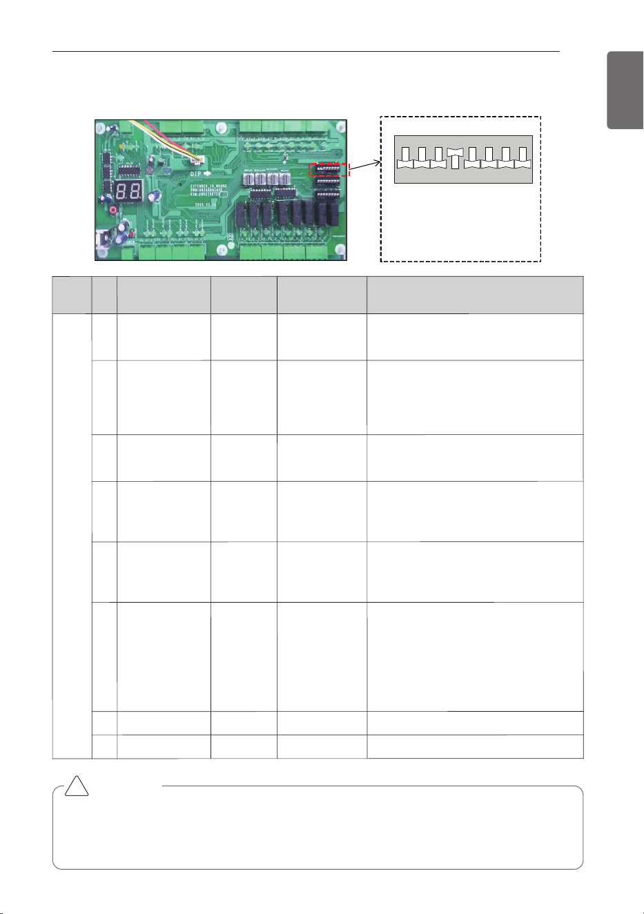
ྚ
* Setting : Black
[Default setting]
- . No 1/2/3/4/6/7/8 : On
- . No 5 : Off
876 543 21
OFF
876 543 21
SW03_SW
② Dip S/W(SW03)
S/W
name
No
Item
On
Off
Note
SW03
_SW
1
RS485/IDU
RS485
Not available
-. RS485 : Connect to INTERNET A/B
on ODU unit
2
Master/Slave
Master
Slave
-. Master is default for single unit
installation
-. Master is only one among multiple
unit
3
Control enable /
disable
DI/DO
enable
DO only
enable
-. Enable : DI/DO are enable
-. Disable : DO only are enable
4
Room
Temperature
setting 1
AI
Rot.S/W
-. AI : Input as analog input
(Controlled through DDC)
-. Rot. S/W : manual setting
5
Air flow rate
High/Low
High/Mid/Low
-. On : Mid step is not available.
(Mid step is displayed as current
step)
6
Room
Temperature
setting 2
Default
AI / Rot. S/W
Room Temperature Default setting
-. On : Default(Cooling 18°C (64.4°F),
Heating 30°C (86°F))
-. Off : Room air(or return air) temper-
ature control using Al Signal and
Rotary S/W (Refer to the DIP S/W
No.4)
7
Not available
-
-
-
8
Flash Writing
Normal
On-boarding
-. Default : On
CAUTION
When the Dip S/W No. 6 is On, capacity control is possible and the value of Analogue input
signal for temperature control, Rotary S/W and Remote controller is ignored. In case of set-
ting the temperature of room using Analogue input signal , Rotary S/W and Remote con-
troller, Dip S/W No. 6 have to be Off certainly.
!
20
COMMUNICATION KIT INSTALLATION
ENGLISH
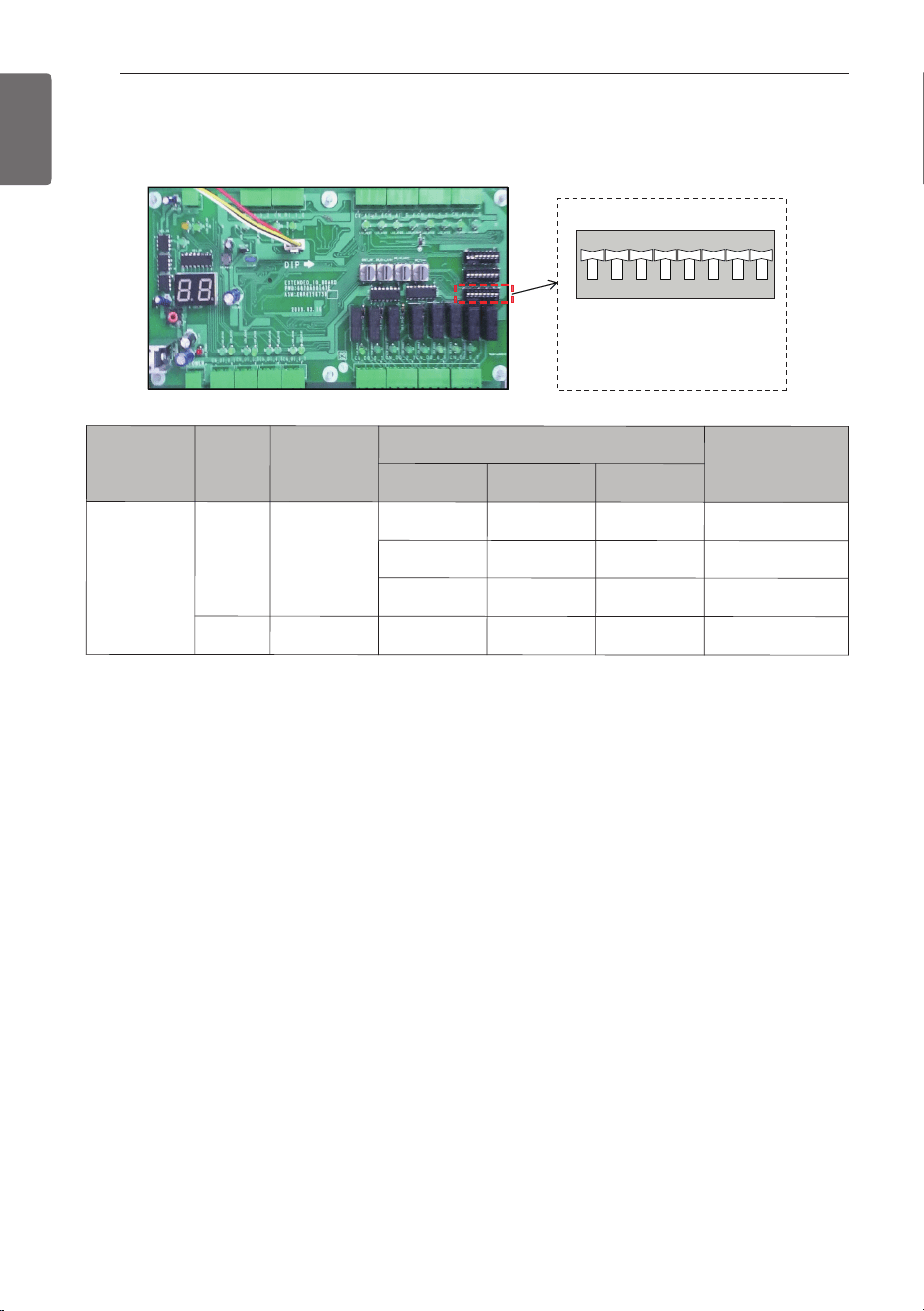
* Setting : Black
[Default setting]
-. No 1/2/3/4/5/6/7/8 : Off
876 543 21
OFF
876 543 21
SW01_SW
ྛ
③ Dip S/W(SW01)
S/W name
No
Item
Setting Dip S/W
AI Function
1
2
3
SW01
_SW
1 ~3
ODU
Capacity
Option
Setting
Off Off Off Option #1
On Off Off Option #2
Off On Off Option #3
4~8 Not available - - - -
COMMUNICATION KIT INSTALLATION
21
ENGLISH
Rotary S/W
ڸ
ڸ
ڹ
ڹ
Rotary S/W
Dip S/W(SW03)
④ Room Temperature control from DDC or Rotary S/W
h
According to Dip S/W(SW03) Setting, you can set up the Function of Room Temperature control.
Dip S/W(② SW03)
Function
Setting
Dip S/W
No 1
ON RS485 Communication with MULTI V
OFF Not available
No 3
ON Possible to control Room Temperature Function (Default)
OFF Only Monitoring (DO Signal only is enable)
No 4
ON DDC Control (Wiring No. AI 10-4)
OFF Rotary S/W(SW_TYPE) Control
No 6
ON
Room Temperature Default setting (Cooling 18°C (64.4°F), Heating 30°C (86°F))
OFF
Room Air(or return air) temperature control using Al signal and Rotary S/W
• Dip S/W(SW03) NO 4 : OFF
Rotary
S/W(①) Number
Room Temp.[°C(°F)] Cooling Room Temp.[°C(°F)] Heating
0 Not available Not available
1 18 (64.4) 16 (60.8)
2 18 (64.4) 17 (62.6)
3 18 (64.4) 18 (64.4)
4 19 (66.2) 19 (66.2)
5 20 (68) 20 (68)
6 21 (69.8) 21 (69.8)
7 22 (71.6) 22 (71.6)
8 23 (73.4) 23 (73.4)
9 24 (75.2) 24 (75.2)
A 25 (77) 25 (77)
B 26 (78.8) 26 (78.8)
C 27 (80.6) 27 (80.6)
D 28 (82.4) 28 (82.4)
E 29 (84.2) 29 (84.2)
F 30 (86) 30 (86)
22
COMMUNICATION KIT INSTALLATION
ENGLISH
• Dip S/W(SW03) NO 4 : ON
Example) 5.85~6.15 Voltage is recognized as 6.0V.
Analog Input 10-4 (VDC)
Room Temp.[°C(°F)]
Cooling
Room Temp.[°C(°F)]
Heating
Normal
Range
Min. Max.
0.5 0 1.15 Not available Not available
1.5 1.35 1.65 18 (64.4) 16 (60.8)
2 1.85 2.15 18 (64.4) 17 (62.6)
2.5 2.35 2.65 18 (64.4) 18 (64.4)
3 2.85 3.15 19 (66.2) 19 (66.2)
3.5 3.35 3.65 20 (68) 20 (68)
4 3.85 4.15 21 (69.8) 21 (69.8)
4.5 4.35 4.65 22 (71.6) 22 (71.6)
5 4.85 5.15 23 (73.4) 23 (73.4)
5.5 5.35 5.65 24 (75.2) 24 (75.2)
6 5.85 6.15 25 (77) 25 (77)
6.5 6.35 6.65 26 (78.8) 26 (78.8)
7 6.85 7.15 27 (80.6) 27 (80.6)
7.5 7.35 7.65 28 (82.4) 28 (82.4)
8 7.85 8.15 29 (84.2) 29 (84.2)
8.5 8.35 8.65 30 (86) 30 (86)
9.5 8.85 10 Not available Not available
CAUTION
If you want to control the Room Temperature using Remote controller, you have to be off
the Dip S/W 4 and Dip S/W 6, and setting the Rotary S/W to the ‘0’ .
!
AHU KIT WIRING CONFIGURATION WITH DDC
23
ENGLISH
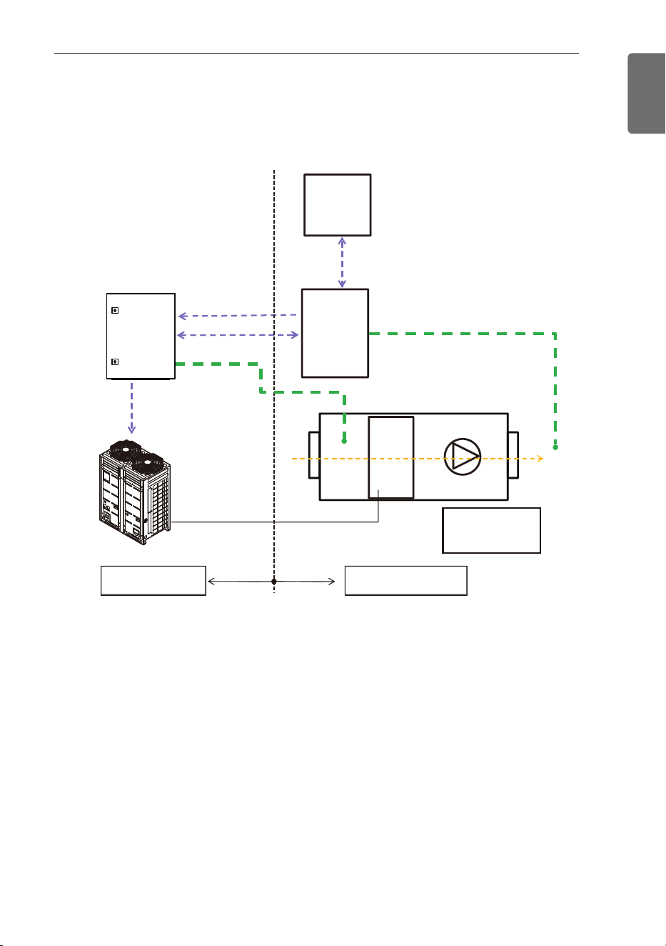
AHU KIT WIRING CONFIGURATION WITH DDC
Configuration concept
AHU
Comm. Kit
(Multi V)
BMS
system
0~10V DC
(AI 10-4)
DI/DO
Room
Temp. sensor
Discharge Temp. sensor
( DC 0~10V Output)
0~10V DC
(AI 10-2)
Target
pressure
Modulating
(AHU)
DDC
TdTeTi
Field SupplyLG Supply
Ti : Inlet Temp.
Te : HEX. Temp.
Td : Discharge Temp.
1 Comm. Kit control capacity of the cooling/heating only according to the DDC’s control
signal (DC 0~10V)
2 Control signal from the DDC is decided by calculation logic with Td/Ti and setting tempera-
ture (Calculation logic depends on BMS program).
3 For Installation of Room thermistor, recommended to be installed to the inlet of Heat
Exchanger.
24
AHU KIT WIRING CONFIGURATION WITH DDC
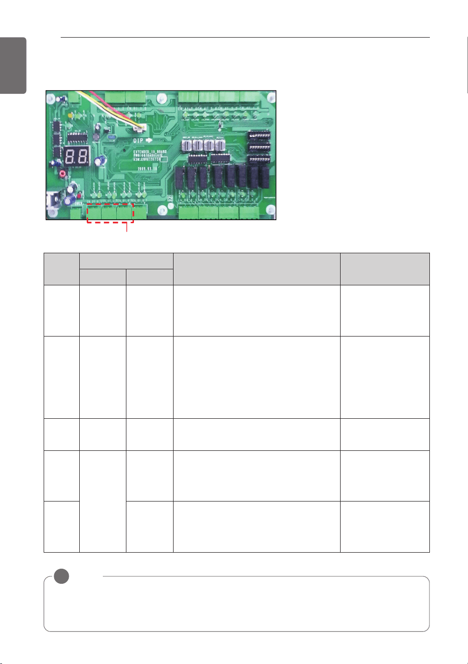
ENGLISH
Digital Input(5ch)
Wiring
No.
Input
Logic Conditions
Open Short
DI 01-3
Operation
Off
Operation
On
-. When short, the fan signal (FAN) is On
and ODU will start to run.
-. When open, ODU will off and FAN
changes to Off.
-. Operation mode
: DI 23-3/23-2
-. Fan mode
: DI 45-3/45-2
DI 23-3
FAN
Operation
Cooling or
Heating
-. When open, FAN is On but ODU will
not run.
-. When short, FAN is On and mode is
decided DI 23-2.
-. If no more cooling and heating is nec-
essary, DI 23-3 is open and DI 01-3 is
On.
-. DI 01-3 : short
DI 23-2
Cooling
Operation
Heating
Operation
-. When open, mode is cooling
-. When short, mode is heating
-. DI 01-3 : short
-. DI 23-3 : short
DI 45-3
Low FAN
Mid FAN
-. When DI 45-3/45-2 are open : Low fan
mode and FAN is On.
-. When DI 45-3 is short : Mid fan and
FAN is On.
-. DI 01-3 : short
-. Operation mode
: DI 23-3/23-2
DI 45-2 High FAN
-. When DI 45-2 short : High fan and
FAN is On.
-. When DI 01-3 is open : FAN is Off, DI
45-3,/45-2 are neglected.
NOTE
!
Fan signal (FAN) can be delayed on heating mode start up despite of fan mode (DI 45-3/45-2)
because fan signal (FAN) will be On , if temperature of refrigerant pipe sensors (PIPE_IN,
PIPE_Out) are higher than 20°C( 68°F) to prevent cold air discharge.
DI Specification
: Non-Voltage Contact
DI Wring concept
AHU KIT WIRING CONFIGURATION WITH DDC
25
ENGLISH
Digital Output(7ch)
NOTE
!
If AHU should have High/Mid/Low fan mode, Fan control in AHU should utilize DO 45-4 /45-2
(Non-Voltage Contact).
Wiring
No.
Output
Logic
Open Short
DO 01-4
Operation
On
Operation
Off
-. When DI 01-3 is short, ODU and FAN are On.
-. When DI 01-3 is open, ODU and FAN are Off.
DO 01-2
Compressor
is Off
Compressor
is On
-. When ODU compressor is running, it is short.
-. When ODU compressor is off, it is open
DO 23-4
Cooling / Heating
Defrosting / FAN
-. When DO 23-4 / 23-2 are open, it is ventilation mode.
-. When DO 23-4 is open, DO 23-2 is short, it is defrosting
during heating. FAN can be OFF if PIPE_IN and
PIPE_OUT are less than
20°C( 68°F)
.
-. When DO 23-4 is short, DO 23-2 is open, it is cooling.
-. When DO 23-4 is short, DO 23-2 is short, it is heating
-. Defrosting mode only works when it is connected with
ODU.
DO 23-2
DO 45-4
Low FAN
Mid FAN
-. When DO 45-4 / DO 45-2 are open, it is low fan mode.
-. When DO 45-4 is short and DO 45-2 is open , it is mid
fan mode.
DO 45-2 High FAN
-. When DO 45-2 is short, it is high fan mode (DO 45-4 is
neglected).
DO 67-4 No Error
Error
Occurred
-. When DO 67-4 is short, ODU has error and ODU stops
FAN is Off.
DO Specification
: AC 250V, DC 30V, 1A
DO Wring concept
26
AHU KIT WIRING CONFIGURATION WITH DDC
ENGLISH
Discharge Temperature Control through controlling of ODU capacity
Analog Input(2ch)
* Setting DIP S/W(SW01)
876 543 21
OFF
876 543 21
1.Option #1
876 543 21
OFF
876 543 21
2.Option #2
876 543 21
OFF
876 543 21
3.Option #3
AI Specification : DC 0~10V
AI
No.
Input
voltage
[Vdc]
Low
[Vdc]
High
[Vdc]
Capacity
of unit
[%]
Cooling
Heating
Control
Target
Low Pres-
sure
[kPa(psi)]
Tempera-
ture at
HEX
[°C(°F)]
Target
High Pres-
sure
[kPa(psi)]
Tempera-
ture at
HEX
[°C(°F)]
AI
10-2
0 0 0.4 No limit ----
DI should be
decided.
1 0.6 1.4 100
800 (116) 10.5 (50.9) 3,000 (435.1) 49.2 (120.6)
DI will determine
fan mode and
operation mode.
2 1.6 2.4 90
830 (120.4) 11.3 (52.3) 2,990 (433.7) 49 (120.2)
3 2.6 3.4 80
870 (126.2) 12.5 (54.5) 2,730 (396) 45.1 (113.2)
4 3.6 4.4 70
930 (134.9) 14 (57.2) 2,560 (371.3) 42.5 (108.5)
5 4.6 5.4 60
990 (143.6) 15.8 (60.4) 2,340 (339.4) 38.9 (102)
6 5.6 6.4 50
1,070 (155.2) 17.9 (64.2) 2,080 (301.7) 34.1 (93.4)
7 6.6 7.4 45
1,100 (159.5) 19 (66.2) 1,950 (282.8) 31.5 (88.7)
8 7.6 8.4 40
1,160 (168.2) 20.3 (68.5) 1,800 (261.1) 28.4 (83.1)
9 8.6 9.4
Comp.
off
----
If it is 9V, DO 01-4
is short, DO 01-2
is open.
10 9.6 10 All off ----
ODU and fan are
Off.
AI Wring concept
1. Option #1
AHU KIT WIRING CONFIGURATION WITH DDC
27
ENGLISH
AI
10-2
0 0 0.4
Comp.
off
----
DO 01-4 is short,
DO 01-2 is open.
1 0.6 1.4
Comp.
off
----
2 1.6 2.4 40
1,160 (168.2) 20.3 (68.5)
1,800 (261.1) 28.4 (83.1)
DI determinará el
modo ventilador y
funcionamiento.
3 2.6 3.4 45
1,100 (159.5) 19 (66.2)
1,950 (282.8) 31.5 (88.7)
4 3.6 4.4 50
1,070 (155.2) 17.9 (64.2)
2,080 (301.7) 34.1 (93.4)
5 4.6 5.4 60
990 (143.6) 15.8 (60.4)
2,340 (339.4) 38.9 (102)
6 5.6 6.4 70
930 (134.9) 14 (57.2)
2,560 (371.3) 42.5 (108.5)
7 6.6 7.4 80
870 (126.2) 12.5 (54.5)
2,730 (396) 45.1 (113.2)
8 7.6 8.4 90
830 (120.4) 11.3 (52.3)
2,990 (433.7) 49 (120.2)
9 8.6 9.4 100
800 (116) 10.5 (50.9)
3,000 (435.1) 49.2 (120.6)
10 9.6 10 100
800 (116) 10.5 (50.9)
3,000 (435.1) 49.2 (120.6)
AI
No.
Input
voltage
[Vdc]
Low
[Vdc]
High
[Vdc]
Capacity
of unit
[%]
Cooling
Heating
Control
Target
Low
Pressure
[kPa(psi)]
Tempera-
ture at
HEX
[°C(°F)]
Target
High
Pressure
[kPa(psi)]
Tempera-
ture at
HEX
[°C(°F)]
AI
No.
Input
voltage
[Vdc]
Low
[Vdc]
High
[Vdc]
Capacity
of unit
[%]
Cooling
Heating
Control
Target
Low
Pressure
[kPa(psi)]
Tempera-
ture at
HEX
[°C(°F)]
Target
High
Pressure
[kPa(psi)]
Tempera-
ture at
HEX
[°C(°F)]
2. Option #2
3. Option #3
AI
10-2
0 0 0.4
Comp.
off
----
DO 01-4 is short,
DO 01-2 is open.
1 0.6 1.4 40
1,160 (168.2)
20.3 (68.5)
1,800 (261.1)
28.4 (83.1)
DI will determine
fan mode and
opeation mode
2 1.6 2.4 45
1,100 (159.5)
19 (66.2)
1,950 (282.8)
31.5 (88.7)
3 2.6 3.4 50
1,070 (155.2)
17.9 (64.2)
2,080 (301.7)
34.1 (93.4)
4 3.6 4.4 60
990 (143.6)
15.8 (60.4)
2,340 (339.4)
38.9 (102)
5 4.6 5.4 70
930 (134.9)
14 (57.2)
2,560 (371.3)
42.5 (108.5)
6 5.6 6.4 80
870 (126.2)
12.5 (54.5)
2,730 (396)
45.1 (113.2)
7 6.6 7.4 90
830 (120.4)
11.3 (52.3)
2,990 (433.7)
49 (120.2)
8 7.6 8.4 100
800 (116)
10.5 (50.9)
3,000 (435.1)
49.2 (120.6)
9 8.6 9.4 100
800 (116)
10.5 (50.9)
3,000 (435.1)
49.2 (120.6)
10 9.6 10 100
800 (116)
10.5 (50.9)
3,000 (435.1)
49.2 (120.6)
28
AHU KIT WIRING CONFIGURATION WITH DDC
ENGLISH
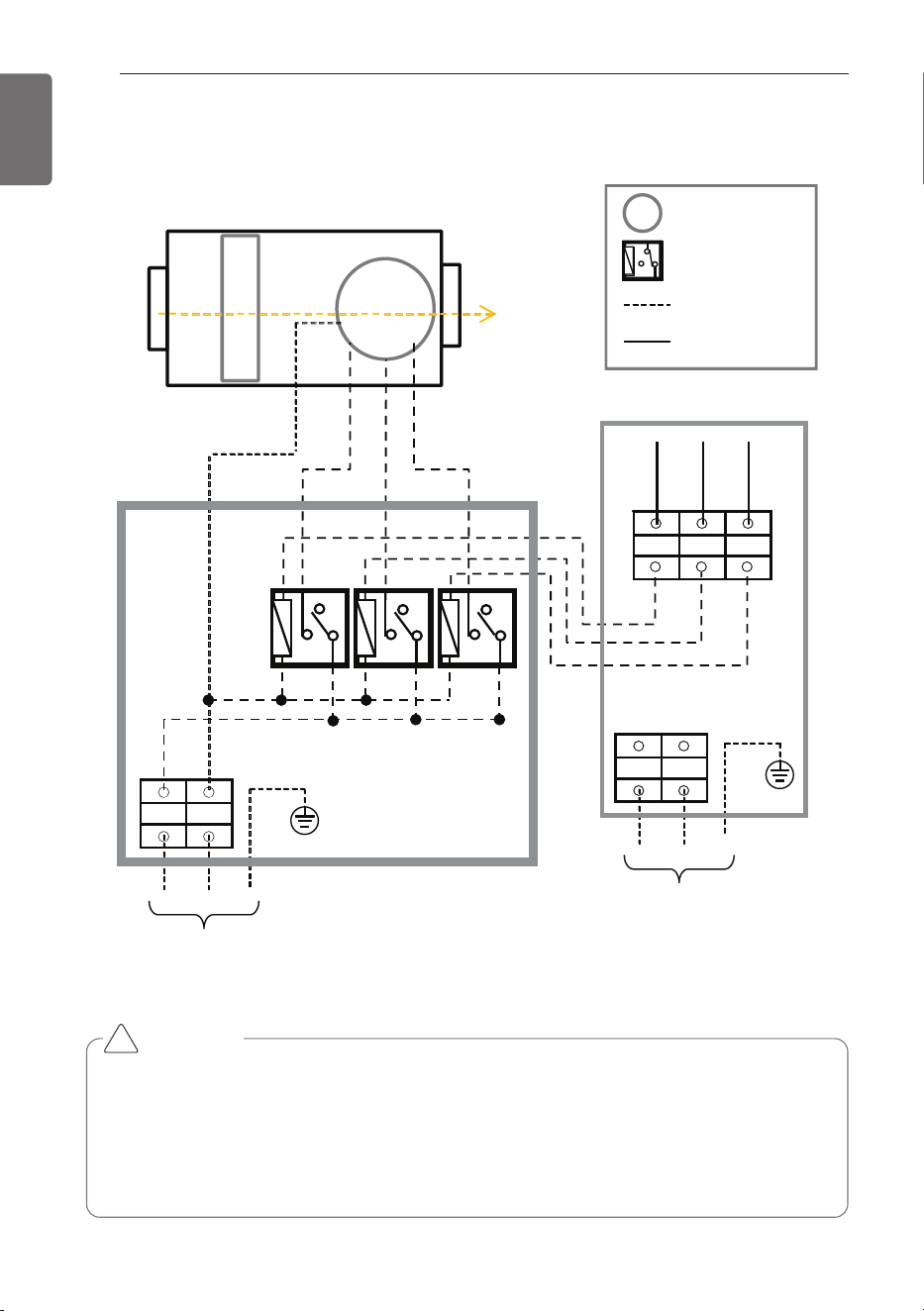
HML
HI
MED
LOW
[AHU Comm. Kit]
HEX
(MCC Panel)
M
N
[AHU]
Motor operating power
1 Ø, 208/230 V ~ 60 Hz
M
Motor
Relay
Field Wiring
Factory Wiring
L1 L2
L1 L2
Control power
1 Ø, 208/230 V ~ 60 Hz
Cable : Over CV 15AWG
R-LOWR-HI R-MED
LOW(L)
MED(L)
HI(L)
FAN Signal Wiring Concept
CAUTION
• If the motor is On/Off type, HI/MED/LOW wire have to connect as common.
For example, If you just connect HI wire to the motor(On/Off), motor is not operating
according to our control logic.
• High, Middle, Low wire from AHU Comm. Kit should not be connected directly to the
motor. Always use it as a motor for driving the relay contacts. Otherwise there is a risk of
damage to product or a fire.
!
THERMISTORS INSTALLATION
29
ENGLISH
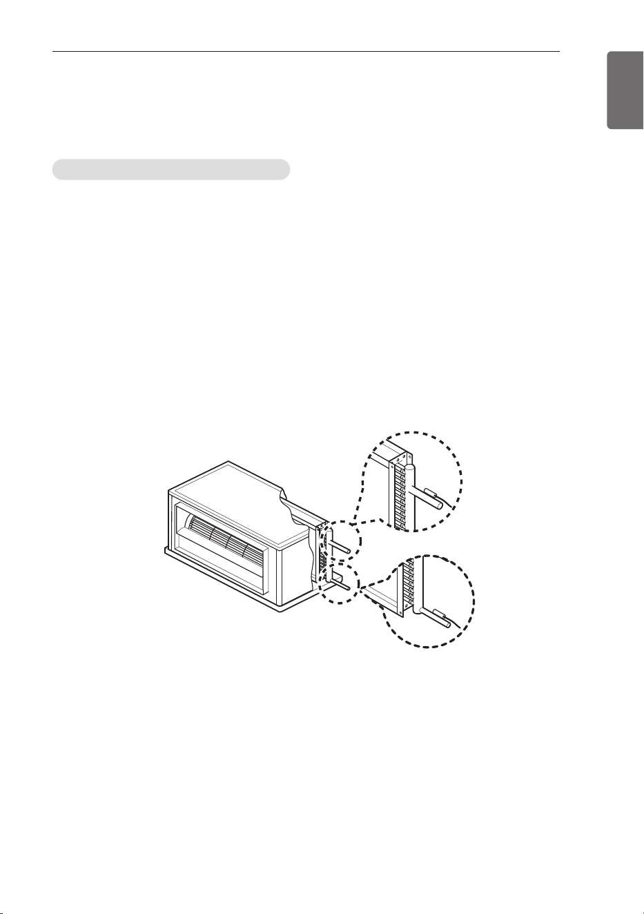
Pipe thermistors Installation
Location of the pipe thermistors
A correct installation of the thermistors is required to ensure a good operation :
1 Pipe_In(EBG62485902)
: Install the thermistor behind the distributor on the coldest pass the heat exchanger
(contact your heat exchanger dealer).
2 Pipe_Out(EBG62485903)
: Install the thermistor at the outlet of the heat exchanger as close as possible to the heat
exchanger.
Evaluation must be done to check if the evaporator is protected against freeze-up.
Execute test operation and check for freeze-up.
1 Pipe_In(Suction pipe)
2 Pipe_Out(Discharge pipe)
1
2
(AHU)
THERMISTORS INSTALLATION
30
THERMISTORS INSTALLATION
ENGLISH
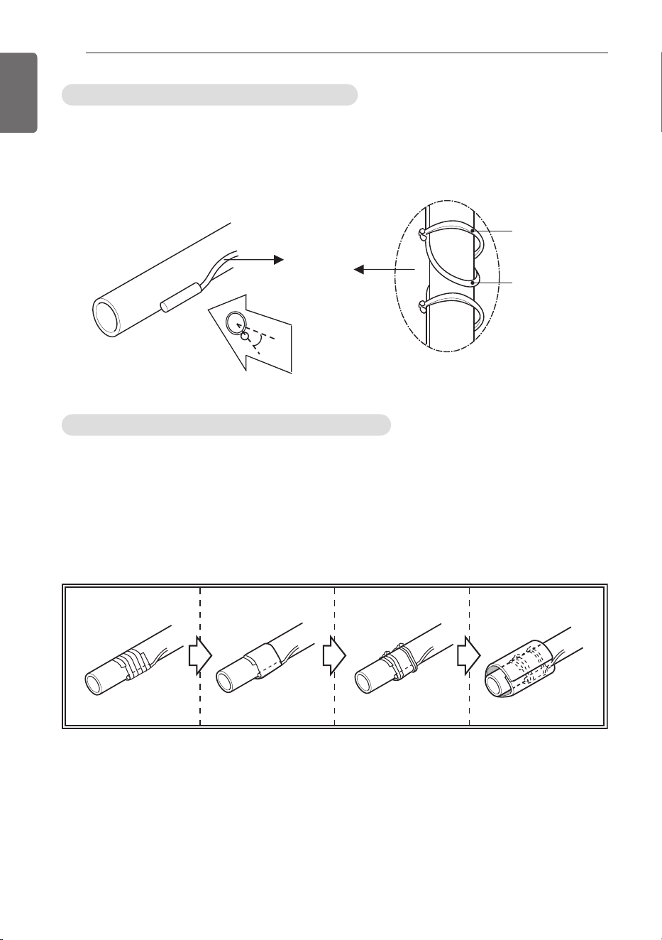
Installation of the pipe thermistor cable
1 Put the thermistor cable in a separate protective tube.
2 Always add a pull-relief to the thermistor cable to avoid strain on the thermistor cable and
loosening of the thermistor. Strain on the thermistor cable or loosening of the thermistor may
result in bad contact and incorrect temperature measurement.
Fixation of the pipe thermistors (Field work)
1 Fix the thermistor with insulating aluminum tape (Field supply) in order to ensure a good heat
transfer.
2 Put the supplied piece of rubber around the thermistor (EBG62485902/EBG62485903) in
order to avoid loosening of the thermistor after some years.
3 Fasten the thermistor with 2 tie wraps (Field Supply)
4 Insulate the thermistor with insulation sheet (Over 5t, Field Supply)
2
Tie wrap
Thermistor
45°
1
1234
THERMISTORS INSTALLATION
31
ENGLISH
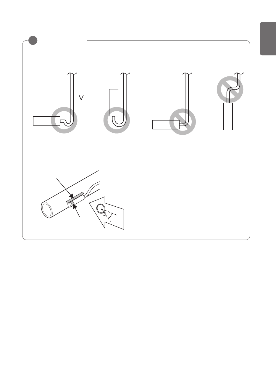
INSTRUCTION
!
• Put the thermistor wire slightly above to avoid water accumulation on down of the ther-
mistor.
• For sensing the evaporator’s temp. in thermistor, Put the upper port of the thermistors on
the evaporator, this is the most sensitive point of the thermistor.
Water
45°
2
1
1 Most sensitive point of the thermistor
2 Maximize the contact
32
TROUBLESHOOTING
ENGLISH
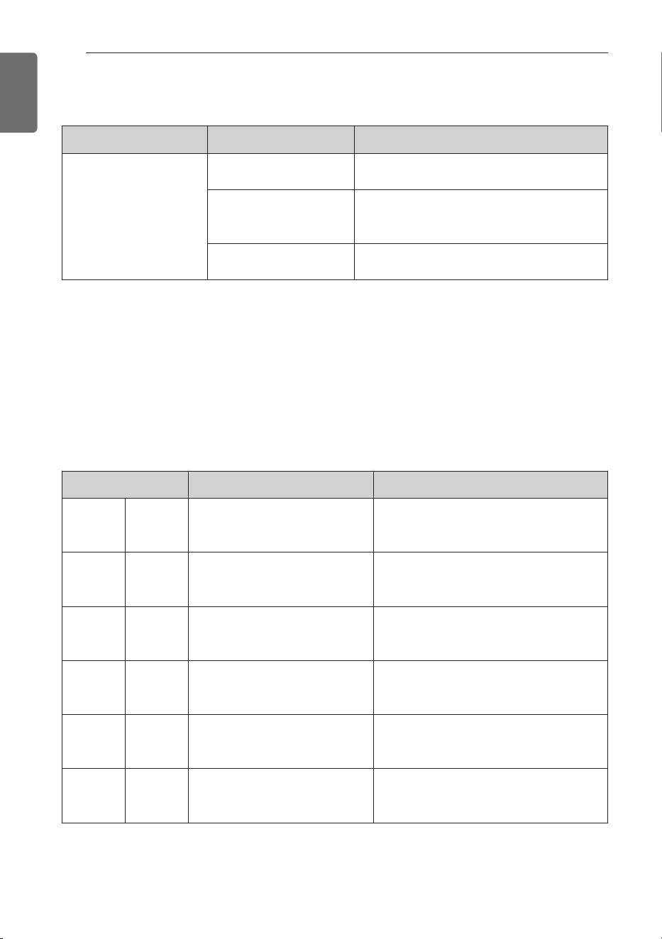
[Error Code (Comm.Kit)]
Display Number Error Item Cause of Error
CH 01 Room Temperature
Temperature sensor disconnection or
short circuit on Room or RA of AHU
CH 02
Pipe In Temperature sensor
error
Temperature sensor disconnection or
short circuit on pipe inlet of AHU
CH 03
Communication error between
wired remote controller and
Comm. Kit
No communication signal for more
than 3 minutes from wired remote
controller to the Comm. Kit
CH 05
Communication error between
Comm.
Kit and Outdoor Unit
No communication signal for 5 minutes
continuously from Comm. Kit to Out-
door Unit
CH 06
Pipe Out Temperature sensor
error
Temperature sensor disconnection or
short circuit on pipe outlet of AHU
CH 09 Option PCB EEPROM error
No reading signal for 5 times continu-
ously from EEPROM to Comm. Kit
Problem Cause Remedy
AHU Communication Kit
does not work
No power supply
Check the electrical connection and voltage
of the power supply.
Wiring is wrong
Check the electrical connection of the
Communication Kit (Refer to the circuit dia-
gram of the Communication Kit)
AHU Communication Kit
is broken
Check the electrical and mechanical part.
TROUBLESHOOTING
Error Indicator
- This function indicates types of failure in self-diagnosis and occurrence of failure for air condi-
tion.
- Error mark is displayed on wired remote controller, and 7-segment LED of outdoor unit control
board as shown in the table.
- If more than two troubles occur simultaneously, lower number of error code is first displayed.
- After error occurrence, if error is released, error LED is also released simultaneously.
TROUBLESHOOTING
33
ENGLISH
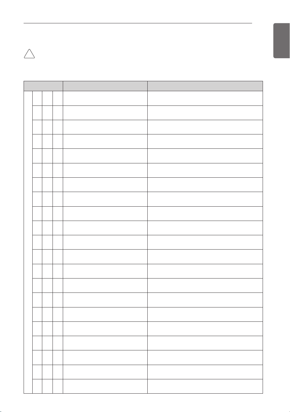
Display Title Cause of Error
Outdoor unit related error
2 1 1
Outdoor unit Inverter Compressor
IPM Fault
Outdoor unit Inverter Compressor Drive IPM Fault
2 2 1
Inverter Board Input Over
Current(RMS) of Outdoor Unit
Outdoor unit Inverter Board Input Current excess
(RMS)
2 3 1
Outdoor unit Inverter Compressor
DC link Low Voltage
DC charging is not performed at Outdoor unit
after starting relay turn on.
2 4 1
Outdoor unit High Pressure Switch
System is turned off by Outdoor unit high pres-
sure switch.
2 5 1
Outdoor unit Input Voltage High/
Low Voltage
Outdoor unit input voltage is over 487V or below
270V
2 6 1
Outdoor unit Inverter Compressor
Start Failure
The First Start Failure by Outdoor unit Inverter
Compressor Abnormality
2 8 1
Outdoor unit Inverter DC link High
Voltage
System is turned off by Outdoor unit DC Voltage
Over Charging
2 9 1
Outdoor unit Inverter Compressor
Over Current
Outdoor unit Inverter Compressor Fault OR Drive
Fault
3 0 1
Outdoor unit Constant Speed Compres-
sor2 High Discharge Temperature
System is turned off by Outdoor Uunit Constant
Speed Compressor2 High Discharge Temperature
3 2 1
Outdoor unit Inverter Compressor
High Discharge Temperature
System is turned off by Outdoor unit Inverter
Compressor High Discharge Temperature
3 3 1
Outdoor unit Constant Speed Compres-
sor1 High Discharge Temperature
System is turned off by Outdoor Uunit Constant
Speed Compressor1 High Discharge Temperature
3 4 1
High Pressure of Outdoor Unit
System is turned off by excessive increase of
high pressure of Outdoor unit
3 5 1
Low Pressure of Outdoor unit
System is turned off by excessive decrease of
low pressure of Outdoor unit
3 6 1
Outdoor unit Low Condensing Ratio Limited Outdoor unit stayed under low condensing limit for 3 minutes
4 0 1
Outdoor unit Inverter Compressor
CT Sensor Fault
Outdoor unit Inverter Compressor CT Sensor
open or short
4 1 1
Outdoor unit Inverter Compressor
Discharge Temperature Sensor Fault
Outdoor unit Inverter Compressor Discharge Tem-
perature Sensor open or short
4 2 1
Outdoor unit Low Pressure Sensor Fault
Outdoor unit Low Pressure Sensor open or short
4 3 1
Outdoor unit High Pressure Sensor Fault
Outdoor unit High Pressure Sensor open or short
4 4 1
Outdoor unit Air Temperature Sensor Fault
Outdoor unit Air Temperature Sensor open or short
4 5 1
Outdoor unit Heat Exchanger Tem-
perature Sensor (Front side) Fault
Outdoor unit Heat Exchanger Temperature Sen-
sor(Front side) open or short
4 6 1
Outdoor unit Suction Temperature
Sensor Fault
Outdoor unit Suction Temperature Sensor open or
short
[Error Code (Outdoor Unit)]
CAUTION
• This page is about outdoor error code. It can vary depending on outdoor unit. For more infor-
mation, please refer to the outdoor unit manual.
!
34
TROUBLESHOOTING
ENGLISH
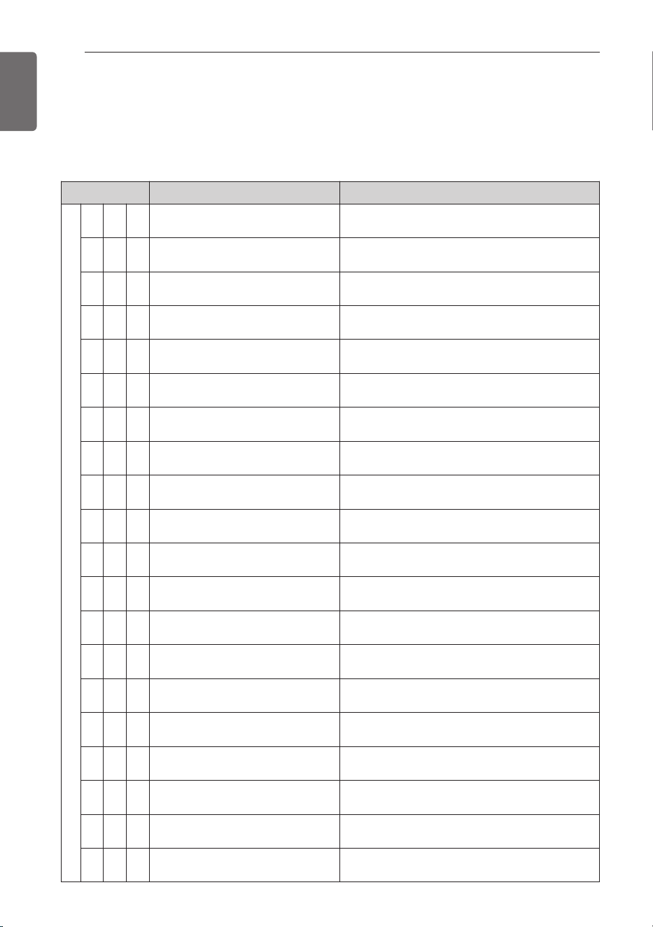
[Error Code (Outdoor Unit)]
CAUTION
• This page is about outdoor error code. It can vary depending on outdoor unit. For more infor-
mation, please refer to the outdoor unit manual.
Display Title Cause of Error
Outdoor unit related error
4 7 1
Outdoor unit Constant Speed Compres-
sor1 Discharge Temperature Sensor Fault
Outdoor unit Constant Speed Compressor1 Dis-
charge Temperature Sensor open or short
4 8 1
Outdoor unit Constant Speed Compres-
sor2 Discharge Temperature Sensor Fault
Outdoor unit Constant Speed Compressor 2 Dis-
charge Temperature Sensor open or short
4 9 1
Outdoor unit Faulty IPM Tempera-
ture Sensor
Outdoor unit IPM Temperature Sensor short/open
5 0 1
Omitting connection of R, S, T
power of Outdoor unit
Omitting connection of outdoor unit
5 1 1
Excessive capacity of indoor units Excessive connection of indoor units compared to
capacity of Outdoor Unit
5 2 1
Transmission error : inverter PCB ’
Main PCB
Failing to receive inverter signal at main PCB of
Outdoor unit
5 3 1
Transmission error : indoor unit ’
main PCB of Outdoor Unit
Failing to receive indoor unit signal at main PCB of
Outdoor Unit .
5 4 1
Reverse connection of R, S, T
power of Outdoor unit
Reverse connection or omitting connection of R,
S, T power of Outdoor unit
5 7 1
Outdoor unit Communication Error
with Inverter Controller
Outdoor unit Controller part cannot receive inverter
control signals (usually happens after on-boarding)
6 0 1
Inverter PCB EEPROM Error of
Outdoor Unit
Access Error of Inverter PCB of Outdoor unit
6 7 1
Outdoor unit Fan Lock Restriction of Outdoor unit
6 9 1
Constant1 CT Sensor Error of Out-
door Unit
Constant1 CT Sensor open or short of Outdoor
unit
7 0 1
Constant2 CT Sensor Error of Out-
door Unit
Constant2 CT Sensor open or short of Outdoor
unit
7 3 1
Instant Over Current(Peak) of Out-
door unit PFC
Instant Over Current(Peak) of Outdoor unit PFC
7 5 1
Outdoor unit Fan CT Sensor Error Outdoor unit Fan CT Sensor open or short
7 6 1
Outdoor unit Fan DC Link High Volt-
age Error
Outdoor unit Fan DC Link High Voltage Error
7 7 1
Outdoor unit Fan Over Current Error Outdoor unit Fan Current is over 5A
7 9 1
Outdoor unit Fan Start Failure Error Outdoor unit Fan First Position Sensing Failure
8 6 1
Outdoor unit Main PCB EEPROM
Error
Communication Fail Between Outdoor unit Main
MICOM and EEPROM or omitting EEPROM
8 7 1
Outdoor unit Fan PCB EEPROM
Error
Communication Fail Between Outdoor unit Fan
MICOM and EEPROM or omitting EEPROM
TROUBLESHOOTING
35
ENGLISH
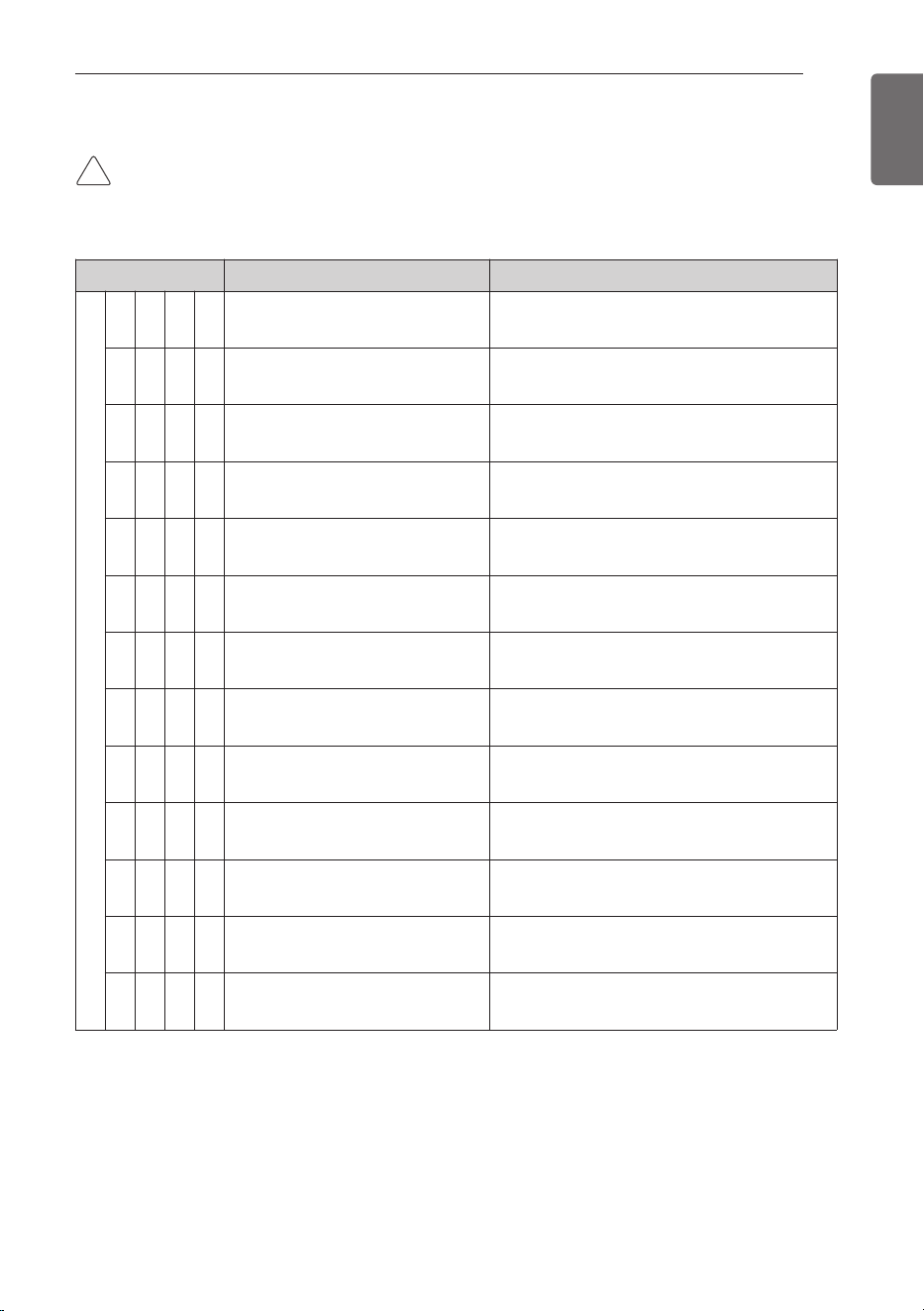
Display Title Cause of Error
Outdoor unit related error
1 0 4 1
Communication Error Between Out-
door unit and Other Outdoor Unit
Failing to receive Slave Unit signal at main PCB
of Outdoor unit
1 0 5 1
Outdoor unit Fan PCB Communica-
tion Error
Failing to receive fan signal at main PCB of
master unit.
1 0 6 1
Outdoor unit FAN IPM Fault Error Instant Over Current at Outdoor unit Fan IPM
1 0 7 1
Outdoor unit Fan DC Link Low Volt-
age Error
Outdoor unit Fan DC Link Input Voltage is
under 380V
1 1 3 1
Outdoor unit Liquid pipe Tempera-
ture Sensor Error
Liquid pipe temperature sensor of Outdoor unit
is open or short
1 1 5 1
Outdoor unit Subcooling Outlet
Temperature Sensor Error
Outdoor unit Subcooling Outlet Temperature
Sensor open or short
1 5 1 1
Failure of operation mode conver-
sion at Outdoor Unit
Pressure unbalance between Outdoor Units
1 7 3 1
Outdoor unit Constant Speed Com-
pressor Fault
Comp locking, Check Valve leakage, comp
dielectric break down at Outdoor Unit
1 7 4 1
Outdoor unit rated speed 2 con-
denser over-current
Outdoor unit rated speed 2 condenser burned /
locked or fault by over-current
1 9 0 1
Excessive increase of outdoor unit
Inverter PCB Heat sink Temperature
Outdoor unit Inverter PCB Heat sink tempera-
ture is over 95°C
1 9 1 1
Outdoor unit Inverter PCB Heat
sink Temperature sensor error
Outdoor unit Inverter PCB Heat sink tempera-
ture sensor open or short
1 9 3 1
Excessive increase of Outdoor unit
Fan PCB Heat Sink Temperature
Outdoor unit Fan Inverter PCB Temperature is
Over 95°C
1 9 4 1
Outdoor unit Fan PCB Heat Sink
Temperature Sensor Error
Outdoor unit Fan PCB Heat Sink Temperature
Sensor open or short
[Error Code (Outdoor Unit)]
CAUTION
• This page is about outdoor error code. It can vary depending on outdoor unit. For more infor-
mation, please refer to the outdoor unit manual.
!

36
ENGLISH