Loading ...
Loading ...
Loading ...
T8775A,C THE DIGITAL ROUND
™
NON-PROGRAMMABLE THERMOSTATS
68-0279 4
4. Tap the provided wall anchors into the drilled holes until
they are flush with the wall.
5. Pull the thermostat wires through the wiring hole on the
wallplate and reposition the wallplate over the wall
anchors.
6. Attach the wallplate to the wall with the screws pro-
vided.
7. After wiring the wallplate, plug the hole to prevent drafts
from affecting the thermostat; see Wiring section.
WIRING
IMPORTANT
Use 18-gauge wire to wire the T8775A,C
Thermostats.
All wiring must comply with local electrical codes and
ordinances. Disconnect the power supply to prevent electrical
shock or equipment damage.
NOTE: To ensure proper mounting of thermostat, restrict all
wiring to the shaded area. See Fig. 5.
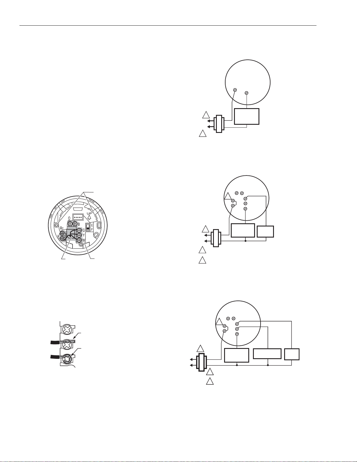
Fig. 5. Restrict T8775 wiring to shaded area.
The shape of the terminals permits insertion of straight or
wraparound wiring connections; either method is acceptable.
See Fig. 6.
Fig. 6. T8775 wiring connections.
Refer to Fig. 7 through 11 for typical wiring diagrams.
Fig. 7. Typical hookup of T8775A in a heat-only system.
Fig. 8. Typical hookup of T8775C in heat-only system with
fan.
Fig. 9. Typical hookup of T8775C in heat-cool system with
single transformer.
M1968
0
WIRING
HOLE
RESTRICT WIRIN
G
TO SHADED ARE
A
MOUNTING
HOLES
M19496
FOR WRAPAROUND
INSERTION STRIP
7/16 IN. (11 MM).
FOR STRAIGHT INSERTIO
N
STRIP 5/16 IN. (8 MM).
POWER SUPPLY. PROVIDE DISCONNECT MEAN
S
AND OVERLOAD PROTECTION AS REQUIRED.
W
R
HEATING
RELAY OR
VALVE COIL
M1951
3
1
1
M1951
4
HEATING
RELAY OR
VALVE COIL
FAN
RELAY
1 POWER SUPPLY. PROVIDE DISCONNECT MEAN
S
AND OVERLOAD PROTECTION AS REQUIRED.
2 FACTORY INSTALLED JUMPER.
1
2
W
R
Rc
B
O
Y
G
1
HEATING
RELAY OR
VALVE COIL
COMPRESSOR
CONTACTOR
FAN
RELAY
M1951
5
1 POWER SUPPLY. PROVIDE DISCONNECT MEAN
S
AND OVERLOAD PROTECTION AS REQUIRED.
2 FACTORY INSTALLED JUMPER.
2
W
R
Rc
B
O
Y
G
Loading ...
Loading ...
Loading ...