Loading ...
Loading ...
Loading ...
Operating Instructions
1-7
1-7
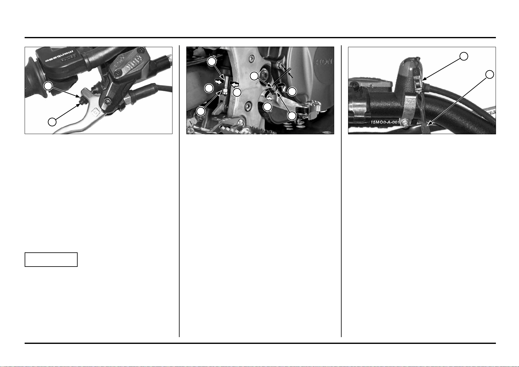
Engine Stop Switch/Safety Lanyard
Pull the engine stop switch (1) (red) until the engine stops
completely.
The safety lanyard (2) should be worn around the
operator’s left wrist. Before starting the engine, install the
safety lanyard to the engine stop switch magnetic base.
If the operator falls away from the controls, the engine
will stop immediately when the safety lanyard is pulled
away from the engine stop switch magnetic base.
(1) ENGINE STOP SWITCH
(2) SAFETY LANYARD
(1) LOCK NUT
(2) ADJUSTING BOLT
(A) RAISE THE PEDAL HEIGHT
(B) LOWER THE PEDAL HEIGHT
Brake Pedal Height
The brake pedal height can be adjusted to the rider’s pre-
ference.
To adjust the rear brake pedal height:
1. Loosen the push rod lock nut and brake pedal adjusting
bolt lock nut. Then turn the both adjusting bolts in
direction “A” to raise the pedal, or in direction “B” to
lower it.
2. Tighten the lock nuts at the desired pedal height.
3. After adjustment, check the brake pedal free play at
the top of the pedal.
Make sure that the clearance between the front adjus-
ting bolt and frame is at least 1 mm (0.04 in).
Front Brake Lever
The front brake lever free play can be adjusted by turning
the adjuster.
Free play must be adjusted to provide 0.1 – 1.4 mm
(0.004 – 0.055 in) clearance between the end of the ad-
juster and the front brake master cylinder piston.
To increase free play, turn the adjuster clockwise, then
tighten the lock nut securely.
If the brake lever free play exceeds 30 mm (1.2 in) even
though the end of the adjuster and the front brake master
cylinder piston is adjusted to the minimum of 0.1 mm
(0.004 in), there is probably air in the brake system and
it must be bled.
NOTICE
Do not adjust the end of the adjuster and the front brake
master cylinder piston below 0.1 mm (0.004 in).
(1) ADJUSTER
(2) LOCK NUT
A
A
B
B
1
1
2
2
1
1
2
2
Loading ...
Loading ...
Loading ...