Loading ...
Loading ...
Loading ...
16
7c
9c
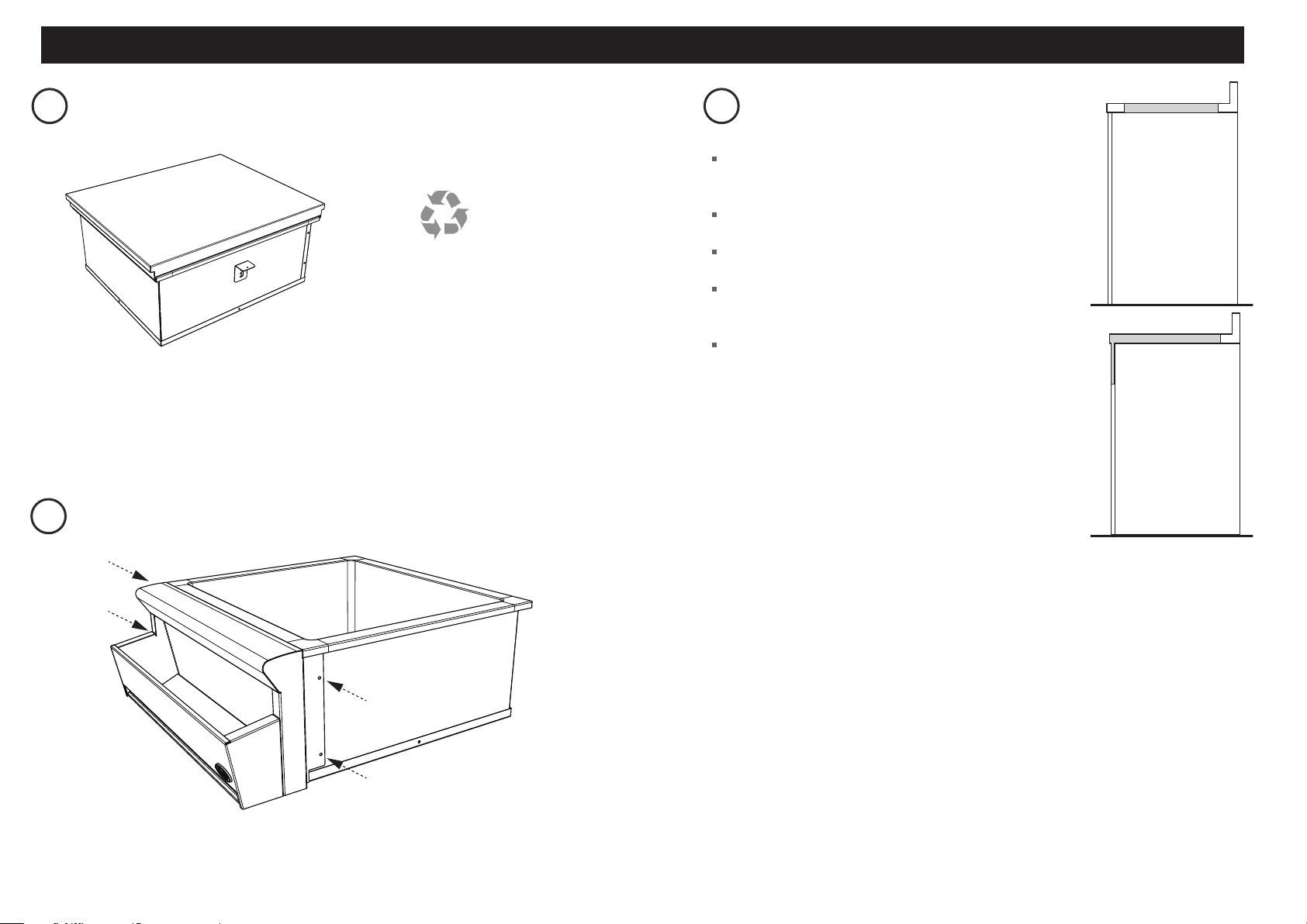
METTEZ L’EMBALLAGE AU REBUT
FIXATION OPTIONNELLE DU PORTE-BOUTEILLE
(VENDU SÉPARÉMENT) AU REFROIDISSEUR DE BOISSON
GAS
ON
GAS
ON
1
2
Fibre washer
Floating nut
Elbow (½” BSP external thread)
Foam Tape
Adhesive side
20 mm
50 mm
+50 mm
NG
ALL Models
Make sure the connection point will be accessible with the cooktop installed.
To enable the gas supply to be readily shut o by the customer, make sure the connection
is tted with an isolating valve close to the cooktop.
Make sure to t the supplied
washer and regulator.
Adjust to obtain a test point
pressure of 1 kPa with the two
semi-rapid burners operating at
highest setting.
Ensure the hose is long enough to allow for removal of cooktop for servicing.
Make sure the connector is located as shown in step 5 CLEARANCE DIMENSIONS.
The hose assembly must be AS/NZS 1869 Class B or D certied, with an Rp ½” (ISO 7‐1) female thread connection.
The hose assembly must be as short as practicable and comply with relevant AS 5601/NZS 5261 requirements.
The hose must not be kinked, subjected to abrasion or permanently deformed.
The hose must not be near or in contact with any hot surfaces
(e.g. base of metal hotlplate, ue, or chassis of underbench oven etc.)
If connecting the gas with a exible hose:
LPG
recessed to 50 mm
check all connections
Make sure to t the supplied
washer and test point adaptor.
Make sure the supply pressure
is regulated to 2.75 kPa, with
the two semi-rapid burners
operating at highest setting.
Washer
Washer
If converting to LPG, see 16 'Converting to a dierent gas type'
To check that the ignition system operates correctly, light each burner by itself, then all burners in combination.
Check for a well‐dened blue ame without any yellow tipping.
If any abnormality is evident, check that the components of the burner assembly are located properly
If proper operation cannot be obtained, contact your nearest F&P Authorised Service Centre.
The cooktop must not be used by the customer until proper operation has been achieved.
yellow tiplifting o
good ame
Arrow
Recyclez de façon
responsable
Le modèle peut être différent des illustrations présentées
Inspectez le(s) produit(s) pour vous assurer qu’aucun dommage n’a été causé lors de l’expédition.
Encas dedommage, communiquez avec l’expéditeur pour faire une demande d’indemnisation. DCS par
Fisher&Paykel n’est pas responsable des dommages causés lors de l’expédition.
REMARQUE: Ne mettez pas au rebut les matériaux d’emballage avant d’avoir terminé l’inspection de
l’appareil.
Examinez le produit afin de vous assurer qu’il ne présente aucune bosselure, égratignure ou décoloration.
each side
13/16” - 2 “
(20-51 mm)
each side
13/16” - 2 “
(20-51 mm)
8c
PRÉPAREZ LA CAVITÉ
Assurez-vous que la base de la cavité est de niveau, à angle
droit et capable de supporter le poids du produit rempli
àpleine capacité.
Toutes les préparations relatives au bâti et/ou au sol
doivent être effectuées avant l’installation.
Toutes les structures de soutien doivent être construites
àl’aide de matériaux résistant à l’humidité.
N’utilisez pas de produits abrasifs (acide, solvant, scellant)
autour de ce produit.
Pour l’installation avec le porte-bouteille (vendu
séparément), l’ouverture doit se prolonger à l’avant
dubâtiafin de laisser de l’espace pour le porte-bouteille
(telqu’illustré).
OUVERTURE SANS
PORTE-BOUTEILLE
OUVERTURE AVEC
PORTE-BOUTEILLE
INSTALLATION DU REFROIDISSEUR DE BOISSON / PORTE-BOUTEILLE (VENDU SÉPARÉMENT)
1
Monter le porte-bouteille sur le devant de la refroidisseur de boissons.
2
Visser le support de bouteille sur le refroidisseur de boisson avec les vis fournies.
3
Déballer le bac d’égouttage et de s’adapter à la partie inférieure du support de bouteille.
Loading ...
Loading ...
Loading ...