Loading ...
Loading ...
Loading ...
49-5000406 Rev. 7 13
Installation Instructions
E1. NON-DUCTED INSTALLATION
(RARMN, RAREN, & RPREN)
1. From inside the RV, double check the gasket’s
position and alignment above the roof opening.
Adjust if necessary. The air conditioner can be
moved and adjusted by pushing upwards from
inside the RV.
2. Reach through the base pan and pull the electrical
power cord from the air conditioner through the
ceiling opening.
3. Measure ceiling to roof thickness.
4. Cut rows from the bottom of the foam baffle
according to the table below:
Ceiling to roof thickness (in) Rows to cut
Minimum Maximum
22.510
2.5 3 8
3.5 4 6
4.5 5 4
55.52
5.5 6 0
Best Practice:
Cut away one row at a time and check installation
position of baffle. With the top foam compressed onto
the air conditioner’s base pan, the bottom of the baffle
should be flush to the ceiling opening.
5. Place foam baffle into position between 2 retainer
plates.
6. Push the mounting template into the roof opening,
and begin hand-threading each of the 4 mounting
bolts through the nuts in the base pan.
7. Tighten the 4 bolts evenly to 35 ± 5 inch pounds
using a torque wrench at least rated for 0-60 in-lbs.
Even compression is required to prevent leaks
through the gasket.
STOP!
For RARMN go to section E2 – Mechanical
Non-Ducted Wiring
For RAREN & RPREN go to section E3 – Electronic
Non-Ducted Wiring
E1. NON-DUCTED INSTALLATION
(RARMN, RAREN, & RPREN)
(cont.)
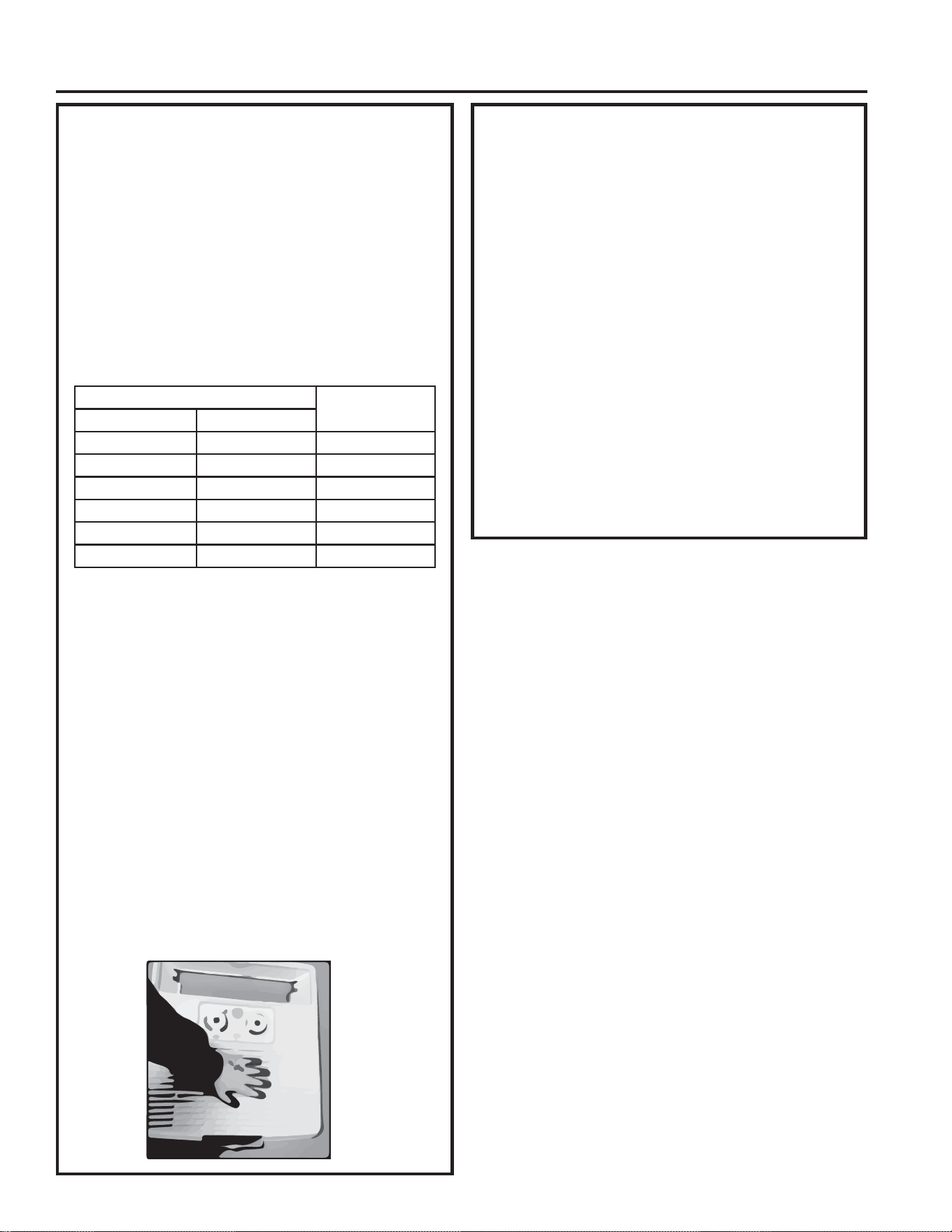
8. Secure the ceiling panel to the mounting template
via 2 sheet metal screws per the 2 holes in the
filter cavity. The filter must be removed to install
the screws.
9. Applying pressure to the center of the ceiling
panel, drive two wood screws in the holes under
the louver located closest to the direct discharge
guide. The side discharge ports should be partially
open or removed to allow access to the mounting
holes.
10. Drive the remaining 6 wood screws located under
the side discharge ports. Access the mounting
holes via the method in the previous step.
11. Reinstall the filter.
12. Installation is complete. Refer to “Controls” on
page 17 Before attempting to operate the air
conditioner.
INSTALLATION INSTRUCTIONS
Loading ...
Loading ...
Loading ...