KMC30X
KMC30BI
KMC30NE
KMC36X
KMC36BI
KMC48NE
KMC48X
KMC48BI
KMC36NE
Installation Instructions
Use and Care Information
Instructions d'installation
Utilisez et d'entretien

2
READ AND SAVE THESE INSTRUCTIONS BEFORE YOU START
INSTALLING THIS RANGEHOOD
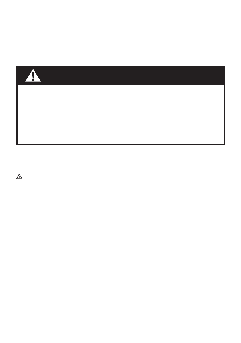
WARNING: - TO REDUCE THE RISK OF A RANGE TOP GREASE FIRE:
a) Never leave surface units unattended at high settings. Boilovers cause smoking and
greasy spillovers that may ignite. Heat oils slowly on low or medium setting.
b)AlwaysturnhoodONwhencookingathighheatorwhenambeingfood(i.e.Crepes
Suzette, Cherries Jubilee, Peppercorn Beef Flambé).
c) Clean ventilating fans frequently. Grease should not be allowed to accumulate on fan
orlter.
d) Use proper pan size. Always use cookware appropriate for the size of the surface element.
WARNING: - TO REDUCE THE RISK OF INJURY TO PERSONS IN THE EVENT OF A
RANGE TOP GREASE FIRE, OBSERVE THE FOLLOWING*:
a)SMOTHERFLAMESwithaclose-ttinglid,cookiesheet,ormetaltray,thenturnofftheburner.
BECAREFULTOPREVENTBURNS.IftheamesdonotgooutimmediatelyEVACUATE
AND CALL THE FIRE DEPARTMENT.
b) NEVER PICK UP A FLAMING PAN - You may be burned.
c) DO NOT USE WATER, including wet dishcloths or towels - a violent steam explosion will
result.
d) Use an extinguisher ONLY if:
1. You know you have a Class ABC extinguisher, and you already know how to operate it.
2. Thereissmallandcontainedintheareawhereitstarted.
3. Theredepartmentisbeingcalled.
4. Youcanghttherewithyourbacktoanexit.
* Based on "Kitchen Firesafety Tips" published by NFPA
WARNING - TO REDUCE THE RISK OF FIRE OR ELECTRIC SHOCK, do not use this
fan with any solid-state speed control device.
WARNING - TO REDUCE THE RISK OF FIRE, ELECTRICAL SHOCK, OR INJURY TO
PERSONS, OBSERVE THE FOLLOWING:
1. Use this unit only in the manner intended by the manufacturer. If you have any
questions, contact the manufacturer.
2. Before servicing or cleaning unit, switch power off at service panel and lock the
service disconnecting means to prevent power from being switched on acciden-
tally. When the service disconnecting means cannot be locked, securely fasten a
prominent warning device, such as a tag, to the service panel.
CAUTION: For General Ventilating Use Only. Do Not Use To Exhaust Hazardous or
Explosive Materials and Vapors.
WARNING - TO REDUCE THE RISK OF FIRE, ELECTRICAL SHOCK, OR INJURY TO
PERSONS, OBSERVE THE FOLLOWING:
1. InstallationWorkAndElectricalWiringMustBeDoneByQualiedPerson(s)InAccor-
dance With All Applicable Codes And Standards, Including Fire-Rated Construction.
2. Sufcientairisneededforpropercombustionandexhaustingofgasesthrough
theue(chimney)offuelburningequipmenttopreventbackdrafting.Followthe
heating equipment manufacturer's guideline and safety standards such as those
publishedbytheNational FireProtectionAssociation(NFPA), and the American
SocietyforHeating,RefrigerationandAirConditioningEngineers(ASHRAE),and
the local code authorities.

3
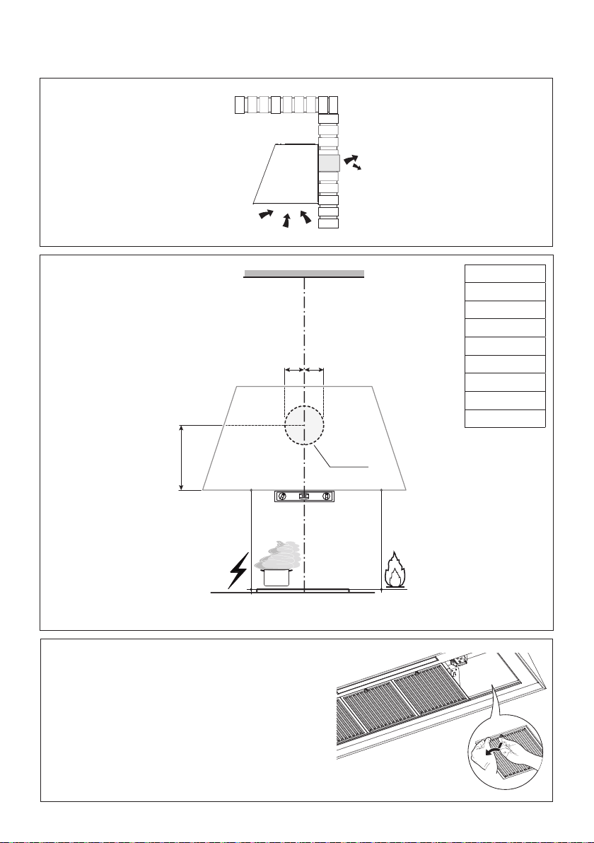
ALL WALL AND FLOOR OPENINGS WHERE THE RANGEHOOD
IS INSTALLED MUST BE SEALED.
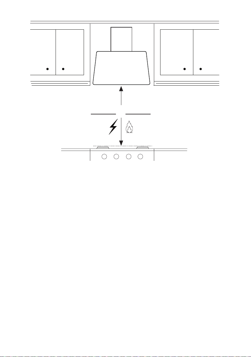
This rangehood requires at least 24" of clearance between the bottom of the rangehood and the
cooking surface or countertop. This hood has been approved by UL at this distance from the cooktop.
This minimum clearance may be higher depending on local building codes. For gas cooktops and
combination ranges, a minimum of 30" is recommended and may be required.
Overhead cabinets on both sides of this unit must be a minimum of 18" above the cooking surface
or countertop. Consult the cooktop or range installation instructions given by the manufacturer before
making any cutouts.
MOBILE HOME INSTALLATION The installation of this rangehood must conform to the Manufactured
Home Construction and Safety Standards, Title 24 CFR, Part 3280 (formerly Federal Standard for
Mobile Home Construction and Safety, Title 24, HUD, Part 280). See Electrical Requirements.
VENTING REQUIREMENTS
Determine which venting method is best for your application. Ductwork can extend either through the
wall or the roof.
The length of the ductwork and the number of elbows should be kept to a minimum to provide efcient
performance. The size of the ductwork should be uniform. Do not install two elbows together. Use
duct tape to seal all joints in the ductwork system. Use caulking to seal exterior wall or oor opening
around the cap.
Flexible ductwork is not recommended. Flexible ductwork creates back pressure and air turbulence
that greatly reduces performance.
Make sure there is proper clearance within the wall or oor for exhaust duct before making cutouts.
Do not cut a joist or stud unless absolutely necessary. If a joist or stud must be cut, then a supporting
frame must be constructed.
WARNING - To Reduce The Risk Of Fire, Use Only Metal Ductwork.
CAUTION-Toreduceriskofreandtoproperlyexhaustair,besuretoductairoutside–Do
not vent exhaust air into spaces within walls or ceilings or into attics, crawl spaces, or garages.
3. When cutting or drilling into wall or ceiling, do not damage electrical wiring and
other hidden utilities.
4. Ducted fans must always be vented to the outdoors.
• Venting system MUST terminate outside the home.
• DO NOT terminate the ductwork in an attic or other enclosed space.
• DO NOT use 4" laundry-type wall caps.
• Flexible-type ductwork is not recommended.
• DO NOT obstruct the ow of combustion and ventilation air.
• Failure to follow venting requirements may result in a re.
WARNING
Cold Weather installations
An additional back draft damper should be installed to minimize backward cold air ow and a
nonmetallic thermal break should be installed to minimize conduction of outside temperatures as
part of the vent system. The damper should be on the cold air side of the thermal break. The break
should be as close as possible to where the vent system enters the heated portion of the house.
4
• Electrical ground is required on this rangehood.
• If cold water pipe is interrupted by plastic, nonmetallic gaskets or other materials, DO
NOT use for grounding.
• DO NOT ground to a gas pipe.
• DO NOT have a fuse in the neutral or grounding circuit. A fuse in the neutral or
grounding circuit could result in electrical shock.
• Check with a qualied electrician if you are in doubt as to whether the rangehood is
properly grounded.
• Failure to follow electrical requirements may result in a re.
WARNING
StateofCaliforniaProposition65Warning(USonly)
WARNING
This product contains chemicals known to the State of California to cause cancer and birth
defects or other reproductive harm.
For more information go to www.P65Warnings.ca.gov
ELECTRICAL REQUIREMENTS
A 120 volt, 60 Hz AC-only electrical supply is required on a separate 15 amp fused circuit. A
time-delay fuse or circuit breaker is recommended. The fuse must be sized per local codes in
accordance with the electrical rating of this unit as specied on the serial/rating plate located inside
the unit near the eld wiring compartment.
5
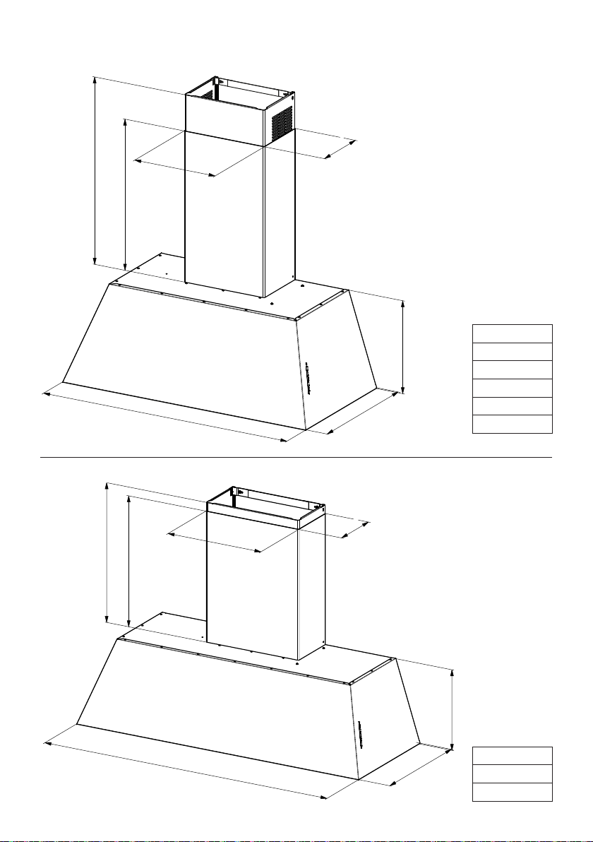
RANGEHOOD DIMENSIONS
KMC30X
KMC30BI
KMC30NE
KMC36X
KMC36BI
KMC36NE
KMC48X
KMC48BI
KMC48NE
18-1/16''
11-13/16''
7-7/8''
20-1/2 ''
MIN AS 21-7/8''- MAX ASP 36''
MIN REC 25-3/8''- MAX REC 39-15/16''
12-5/8''
29-7/8'' - 35-13/16''
Created by
Latini, Francesco
Denomination
DIMENSIONAL DRAWING 30-36''
Lang EN
Sheet
1
/2
Modif.by
Approved by
Approval date
Doc. status
Drawing N.
321033_724
Rev
01
47-7/8''
18-1/16''
15-3/4
''
7-7/8''
20-1/2''
MIN 21-7/8''-MAX 39-15/16''
12-5/8 ''
Created by
Latini, Francesco
Denomination
DIMENSIONAL DRAWING 48''
Lang EN
Sheet
1
/2
Modif.by
Approved by
Approval date
Doc. status
Drawing N.
321033_734
Rev
01

6
Min. 24" Min. 30"

7
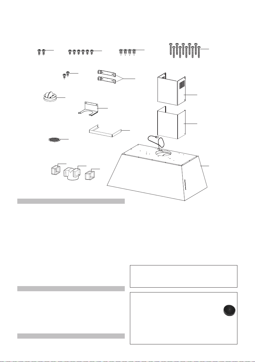
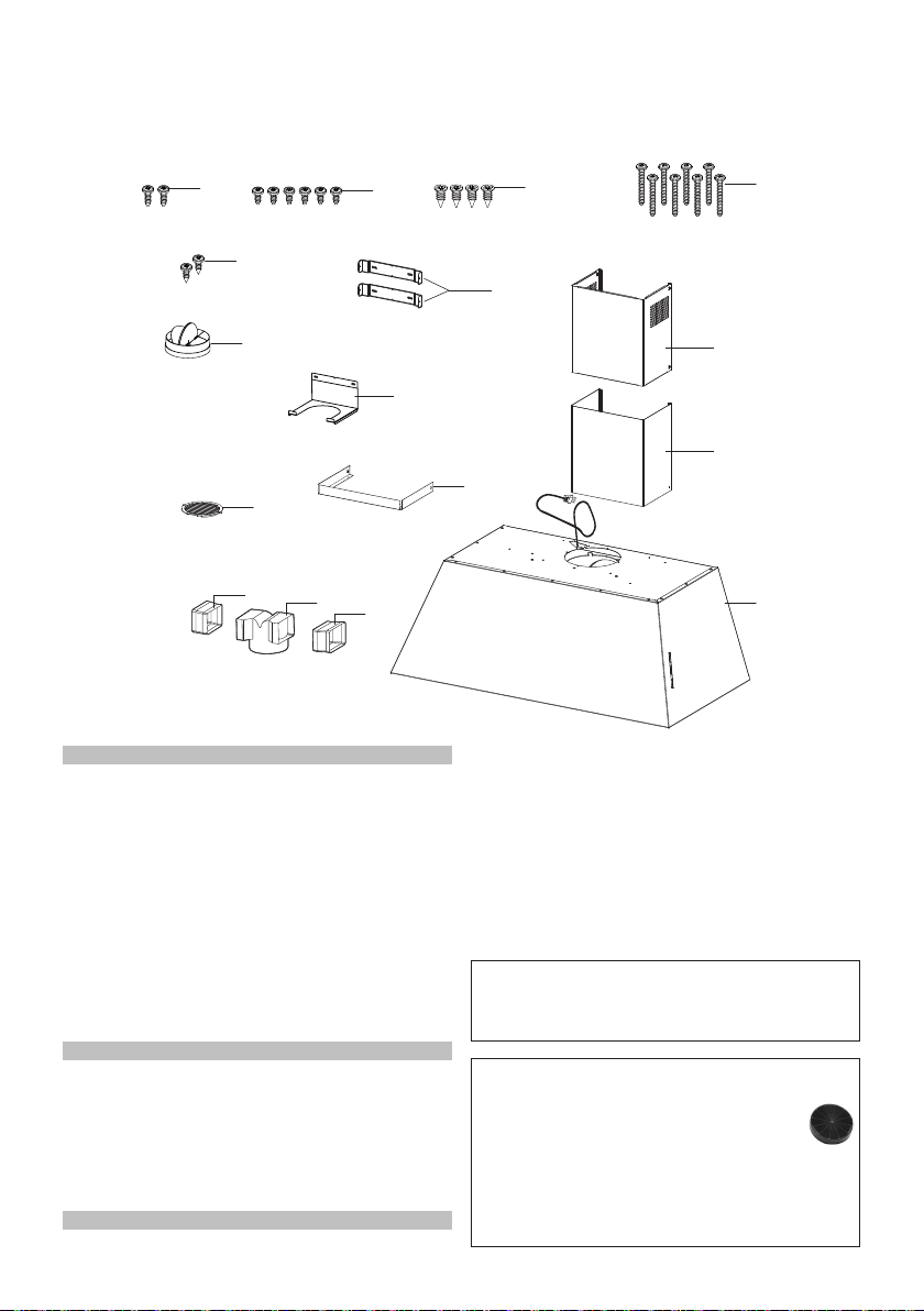
MAIN PARTS
KMC30X - KMC30BI - KMC30NE
Components
Ref. Qty. Product Components
1 1 Hood Body, complete with:
Controls, Light, Filters, Blower.
2 1 Telescopic Chimney comprising:
2.1 1 Upper Section
2.2 1 Lower Section
3 1 Angle bracket
10 1 Damper ø 5 7/8"
10e 1 Support connection for recirculating
9 1 Connection
for recirculating comprising:
9.1 1 Connection for recirculating
9.2 1 Spacer connection for recirculating
9.3 1 Spacer connection for recirculating
8 1 Recirculation Vent Grill
Ref. Qty. Installation Components
7.2.1 2 Upper Chimney Section
Fixing Brackets
12a 8 Screws 3/16" x 1 15/16"
12b 4 Screws 1/8" x 3/8"
12d 6 Screws 1/8" x 1/4"
12e 2 Screws 1/8" x 3/8"
12f 2 Screws 1/8" x 1/2"
Qty. Documentation
1 Instruction Manual
10e
9.2
9.1
9.3
10
12e
12d
12b
12a
8
1
2.1
2.2
7.2.1
3
12f
Available Accessories
- Recirculation Vent Kit - Activated
Charcoal Filter - sku# FILTER1
- Washable Long Lasting Charcoal Filter
Kit - sku# FILTER1LL
- Wireless Remote Control Accessory -
REMCTRL2
Parts needed
- 6" Round Metal ductwork.
8
MAIN PARTS
KMC36X - KMC36BI - KMC36NE
10e
9.2
9.1
9.3
10
12e
12d
12b
12a
8
1
2.1
2.2
7.2.1
3
12f
Components
Ref. Qty. Product Components
1 1 Hood Body, complete with:
Controls, Light, Filters, Blower.
2 1 Telescopic Chimney comprising:
2.1 1 Upper Section
2.2 1 Lower Section
3 1 Angle bracket
10 1 Damper ø 5 7/8"
10e 1 Support connection for recirculating
9 1 Connection
for recirculating comprising:
9.1 1 Connection for recirculating
9.2 1 Spacer connection for recirculating
9.3 1 Spacer connection for recirculating
8 1 Recirculation Vent Grill
Ref. Qty. Installation Components
7.2.1 2 Upper Chimney Section
Fixing Brackets
12a 10 Screws 3/16" x 1 15/16"
12b 4 Screws 1/8" x 3/8"
12d 6 Screws 1/8" x 1/4"
12e 2 Screws 1/8" x 3/8"
12f 2 Screws 1/8" x 1/2"
Qty. Documentation
1 Instruction Manual
Available Accessories
- Recirculation Vent Kit - Activated
Charcoal Filter - sku# FILTER1
- Washable Long Lasting Charcoal Filter
Kit - sku# FILTER1LL
- Wireless Remote Control Accessory -
REMCTRL2
Parts needed
- 6" Round Metal ductwork.
9
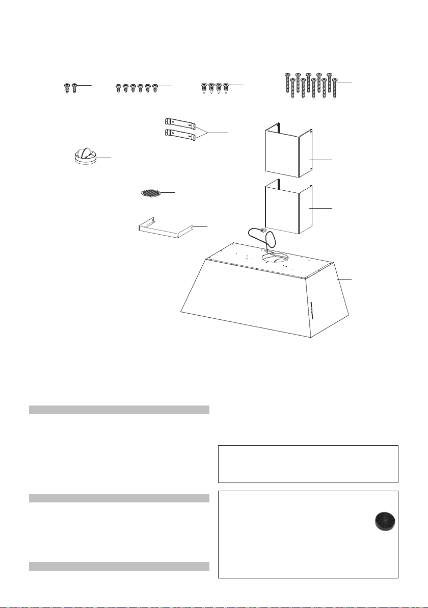
MAIN PARTS
KMC48X - KMC48BI - KMC48NE
10
12e
12d
12b
12a
8
1
2.1
2.2
7.2.1
3
Components
Ref. Qty. Product Components
1 1 Hood Body, complete with:
Controls, Light, Filters, Blower.
2 1 Telescopic Chimney comprising:
2.1 1 Upper Section
2.2 1 Lower Section
3 1 Angle bracket.
10 1 Damper ø 5 7/8"
8 1 Recirculation Vent Grill
Ref. Qty. Installation Components
7.2.1 2 Upper Chimney Section Fixing
Brackets
12a 10 Screws 3/16" x 1 15/16"
12b 4 Screws 1/8" x 3/8"
12d 6 Screws 1/8" x 1/4"
12e 2 Screws 1/8" x 3/8"
Qty. Documentation
1 Instruction Manual
Available Accessories
- Recirculation Vent Kit - Activated
Charcoal Filter - sku# FILTER1
- Washable Long Lasting Charcoal Filter
Kit - sku# FILTER1LL
- Wireless Remote Control Accessory -
REMCTRL2
Parts needed
- 6" Round Metal ductwork.

10
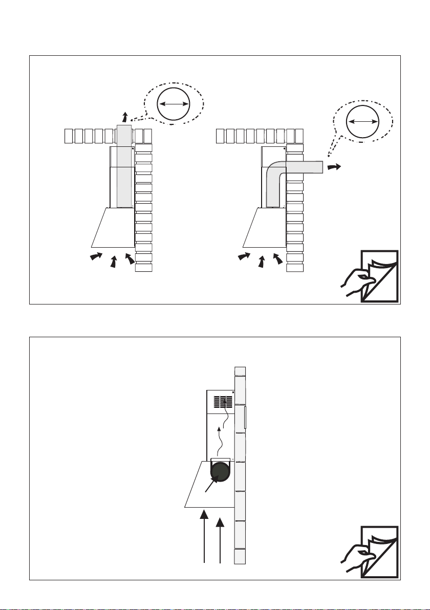
Non Ducted - Recirculation Option
Requires
purchase of
Activated
Charcoal
Accessory.
Horizontal
Vertical
12
19
6"
6"
Choose your ducting method
INSTALLATION WITH THE CHIMNEY
Ducted Venting Installation

11
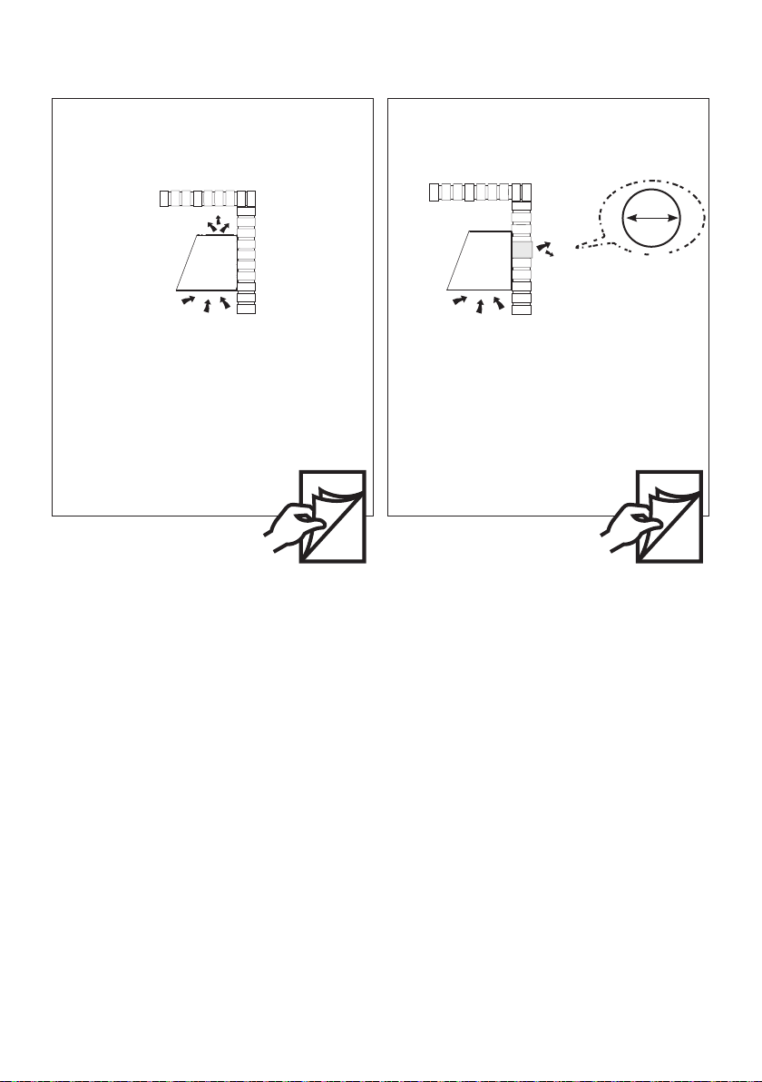
Choose your ducting method
INSTALLATION WITHOUT THE CHIMNEY
Non Ducted - Recirculation Option
Requires purchase of Activated Charcoal Accessory
When used in recirculation mode, To Reduce
the Risk of Fire and Shock use only conversion
kit Model FILTER1 or FILTER1LL.
Ducted Venting Options Installation
6"
Rear
2622

12
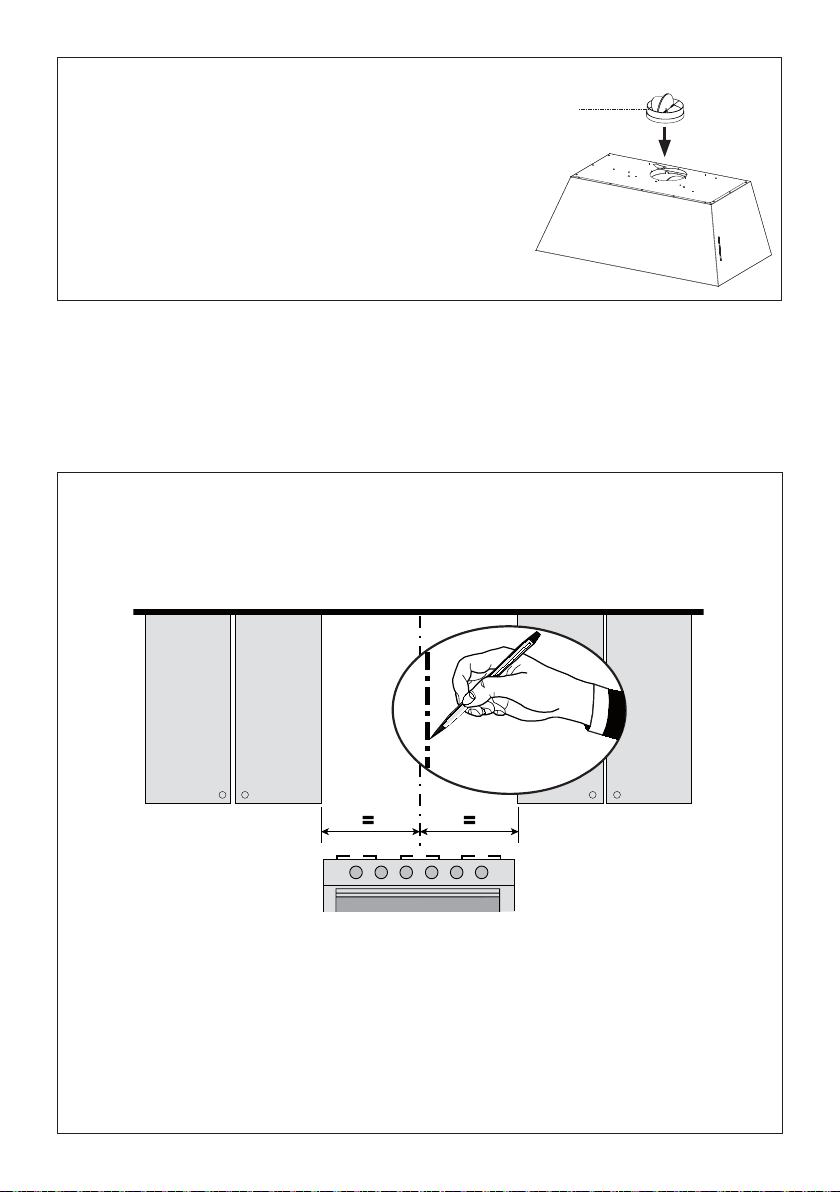
1
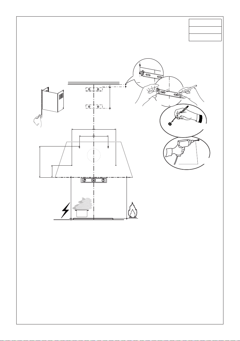
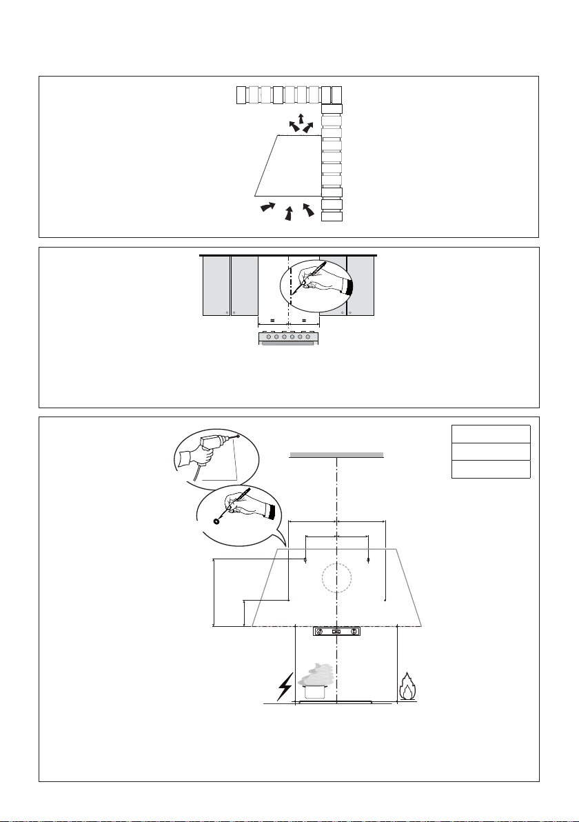
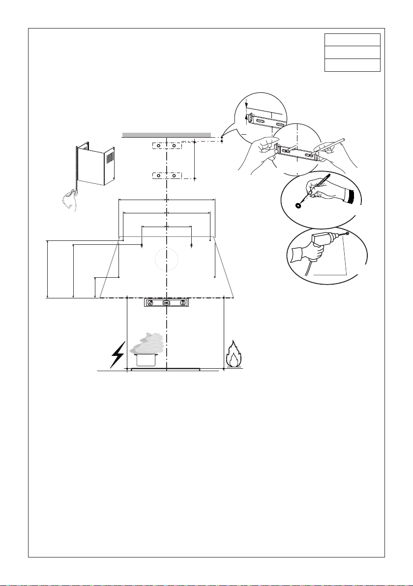
Draw a vertical line on the supporting wall as high as practical, at the center of the area in which
the hood will be installed.
Draw a horizontal line at where the bottom edge of the hood will be located as indicated in the gure
that is a minimum of 24" above Electric cooking surface and 30" above Gas.
Installation Instructions
Install Damper that is included with the Hood
before connecting to the ductwork.
Only for Ducted Venting Installation
H
I
13
2.a
Mark the wall where indicated, 10 7/16" above the horizontal line and at 6 1/2" distance on the left and
right of vertical line. Checking that the two marks are level.
Insert two wall plugs and two screws into the holes as shown not completely (purchased separately).
Mark the wall where indicated, 3 15/16" above the horizontal line and at 9 1/16" distance on the left and
right of vertical line. Checking that the two marks are level.
Insert two wall plugs (purchased separately).
Place a bracket 7.2.1 on the wall as shown about 1 1/8" from the ceiling or upper limit, aligning the center
(notch) with the vertical reference line and mark the wall at the centers of the holes in the bracket.
Place the second bracket 7.2.1 on the wall as shown, below the rst bracket, at the height of the upper
chimney section supplied and aligning the center (notch) with the vertical line.
Mark the wall at the centers of the holes in the bracket and drill ø 5/16" as shown.
Installation screws provided for the Brackets, must be secured with wall plugs (purchased separately).
KMC30X
KMC30BI
KMC30NE
10 7/16"
3 15/16"
6 1/2" 6 1/2"
9 1/16" 9 1/16"
1 1/8”
>
Ø 5/16”
Min.
24"
2.1
Min.
30"
2.1
x8
7.2.1
x8
1
5 6
7 8
7 8
5 6
3 4
1 2
3 4
2
7 8
5 6
3 4
1 2
30"
14
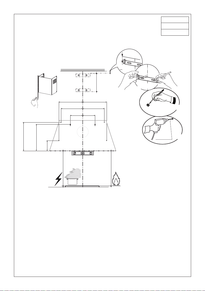
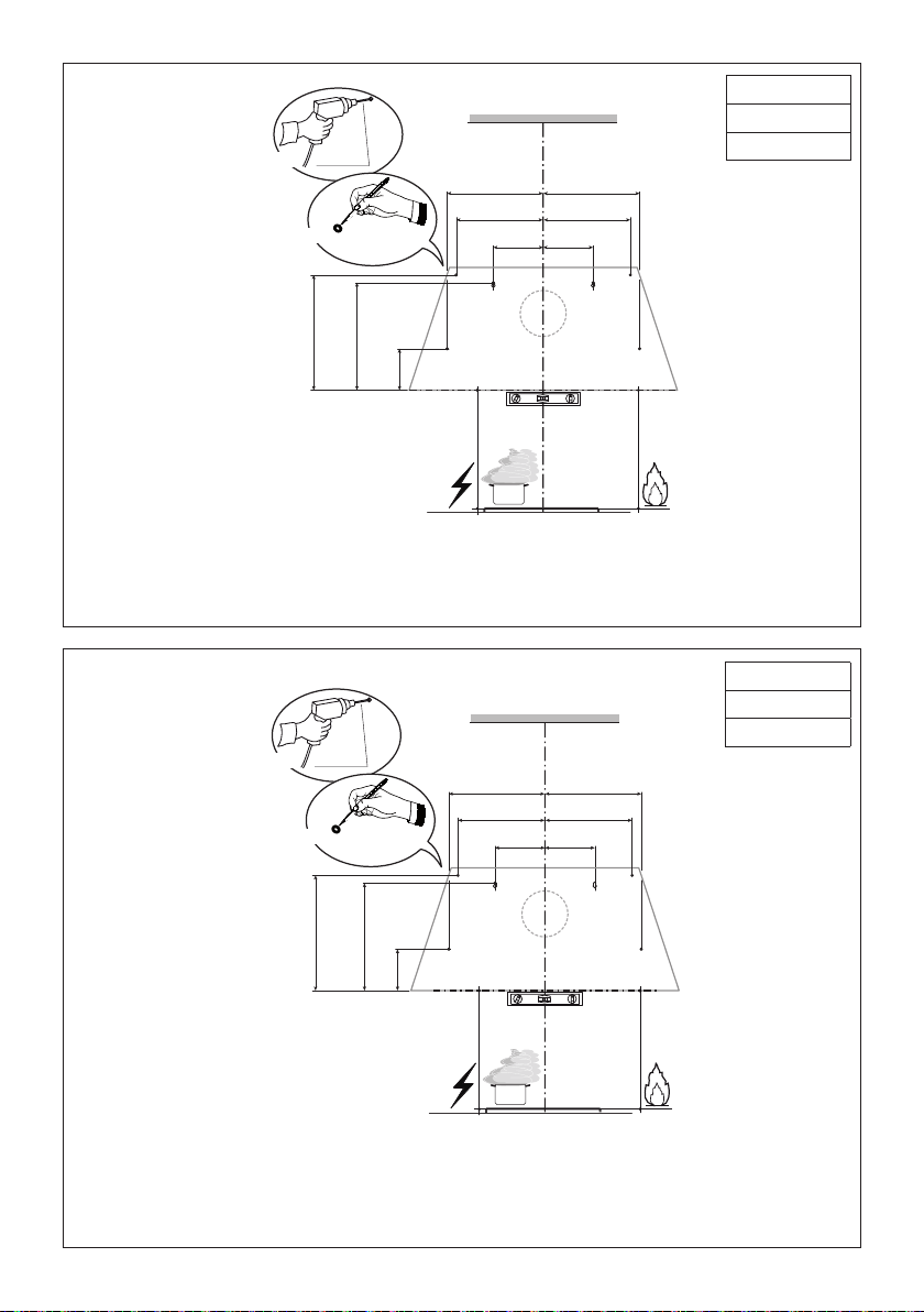
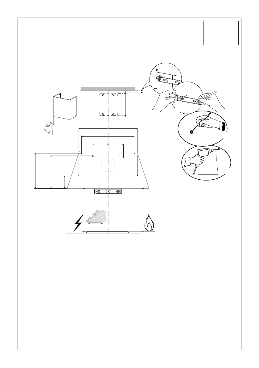
Mark the wall where indicated, 10 7/16" above the horizontal line and at 6 1/2" distance on the left and
right of vertical line. Checking that the two marks are level.
Insert two wall plugs and two screws into the holes as shown not completely (purchased separately).
Mark the wall where indicated, 3 15/16" above the horizontal line and at 13 12/16" distance on the left and
right of vertical line. Checking that the two marks are level. Insert two wall plugs (purchased separately).
Mark the wall where indicated, 11" above the horizontal line and at 12 3/16" distance on the left and
right of vertical line. Checking that the two marks are level. Insert two wall plugs (purchased separately).
Place a bracket 7.2.1 on the wall as shown about 1 1/8" from the ceiling or upper limit, aligning the center
(notch) with the vertical reference line and mark the wall at the centers of the holes in the bracket.
Place the second bracket 7.2.1 on the wall as shown, below the rst bracket, at the height of the upper
chimney section supplied and aligning the center (notch) with the vertical line.
Mark the wall at the centers of the holes in the bracket and drill ø 5/16" as shown.
Installation screws provided for the Brackets, must be secured with wall plugs (purchased separately).
2.b
KMC36X
KMC36BI
KMC36NE
10 7/16"11"
3
15/16"
6 1/2" 6 1/2"
13 12/16" 13 12/16"
12 3/16" 12 3/16"
1 1/8”
>
Ø 5/16”
Min.
24"
Min.
30"
2.1
2.1
7.2.1
x10
x10
1
9 10
7 8
3 4
2
9 10
7 8
5 6
3 4
1 2
9 10
7 8
5 6
3 4
1 2
5
6
36"
15
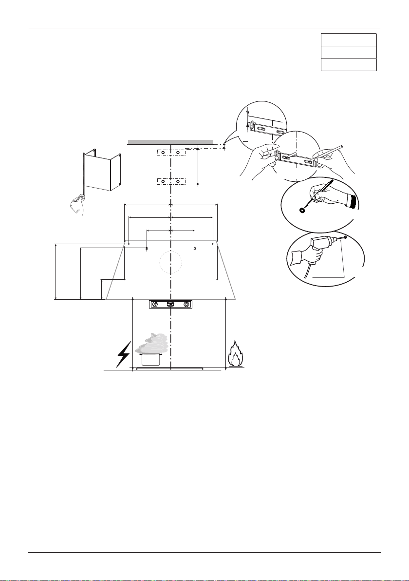
2.c
Mark the wall where indicated, 10 7/16" above the horizontal line and at 6 1/2" distance on the left and
right of vertical line. Checking that the two marks are level.
Insert two wall plugs and two screws into the holes as shown not completely (purchased separately).
Mark the wall where indicated, 3 15/16" above the horizontal line and at 18 14/16" distance on the left and
right of vertical line. Checking that the two marks are level. Insert two wall plugs (purchased separately).
Mark the wall where indicated, 11 6/16" above the horizontal line and at 11 11/16" distance on the left and
right of vertical line. Checking that the two marks are level. Insert two wall plugs (purchased separately).
Place a bracket 7.2.1 on the wall as shown about 1 1/8" from the ceiling or upper limit, aligning the center
(notch) with the vertical reference line and mark the wall at the centers of the holes in the bracket.
Place the second bracket 7.2.1 on the wall as shown, below the rst bracket, at the height of the upper
chimney section supplied and aligning the center (notch) with the vertical line.
Mark the wall at the centers of the holes in the bracket and drill ø 5/16" as shown.
Installation screws provided for the Brackets, must be secured with wall plugs (purchased separately).
KMC48X
KMC48BI
KMC48NE
10 7/16"
3 15/16"
6 1/2" 6 1/2"
1 1/8”
>
Ø 5/16”
Min.
24"
Min.
30"
2.1
2.1
7.2.1
x10
x10
5 6
7 8
9 10
7 8
5 6
3 4
1 2
9 10
7 8
5 6
3 4
1 2
11 6/16"
18 14/16"
18 14/16"
11 11/16" 11 11/16"
1
3 4
2
5
6
48"

16
3
4
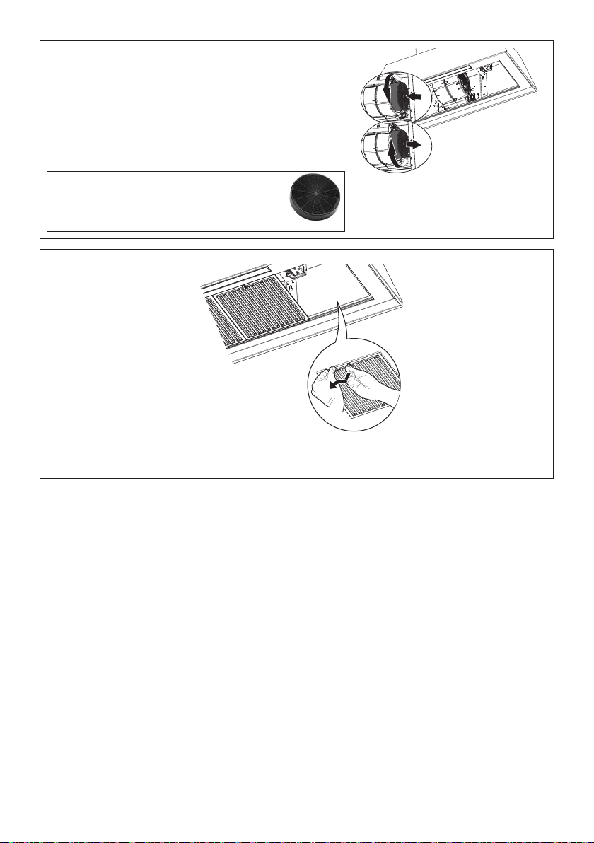
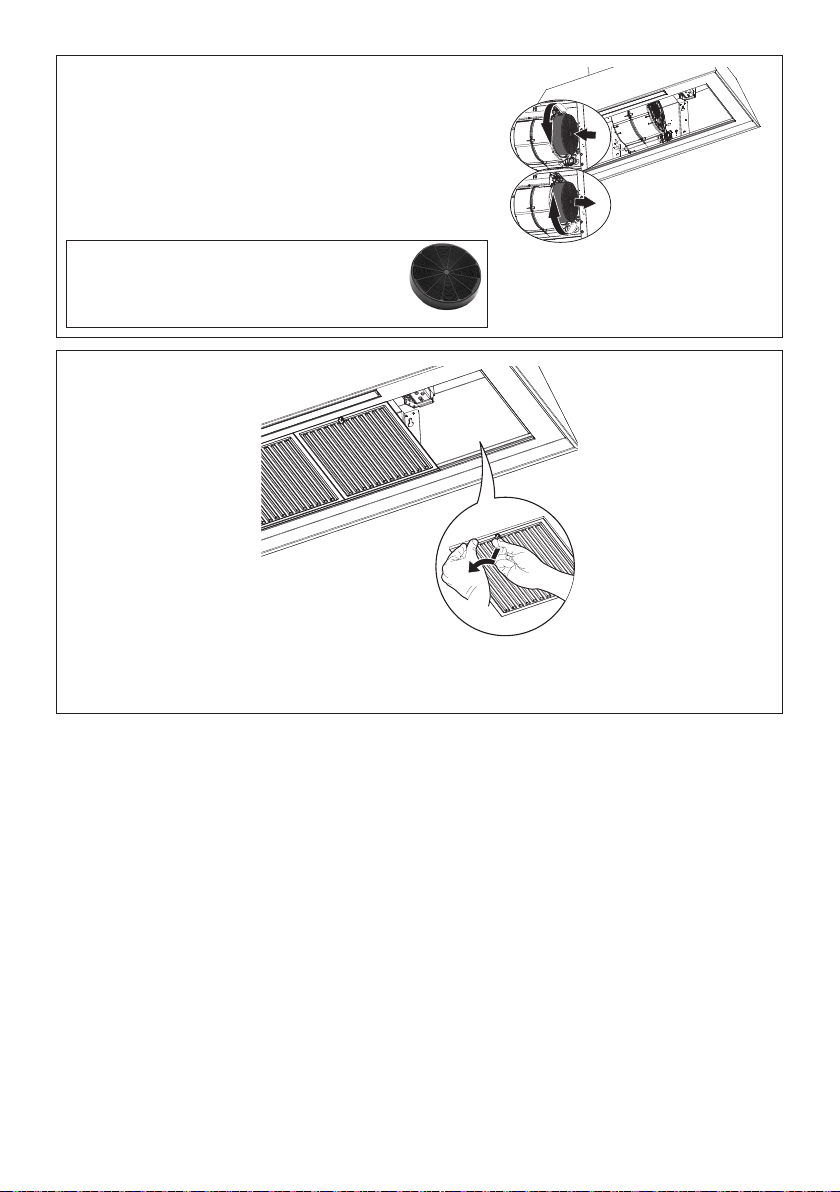
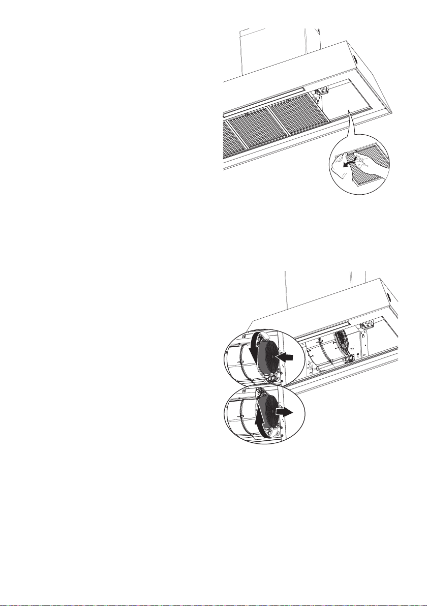
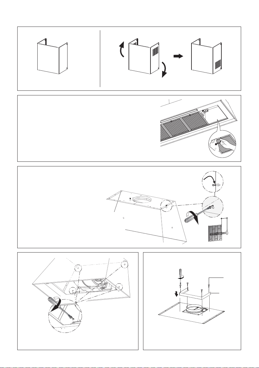
Remove the lters one at a time, supporting them
with one hand and turning the safety knobs (pull
and turn).
Do not discard the lters and set aside for future
use.
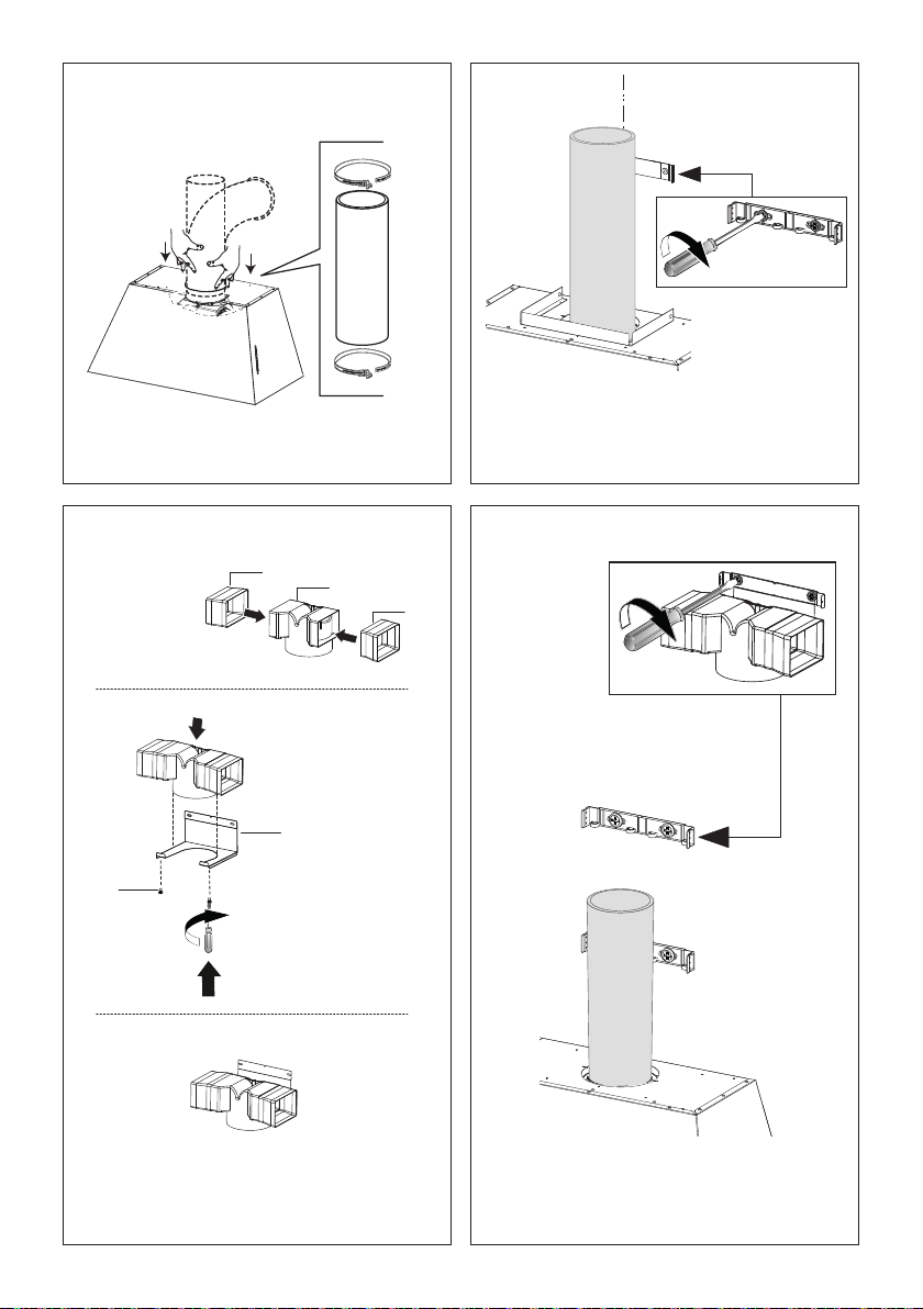
Hook and x the hood body onto
the wall.
INSTALLATION WITH THE CHIMNEY
OK!
3/16”
L
2x
4
3
Z
120
550 min
650 min
120
640
800
Ø 8 mm
4x
I - 4x
6
5
420
L
4x
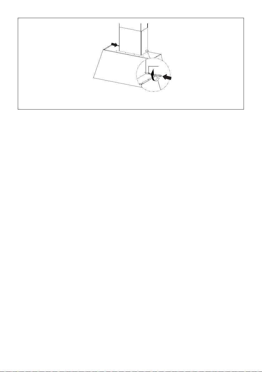
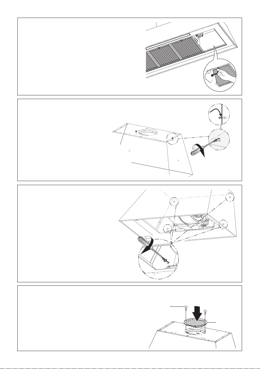
Use the four screws to secure the angle
bracket.
From inside fully secure the screws 12a.
5 6
3
12d
4x

17
7
9
Ø 150
O
Ø 120
8
L
4x
M
2x
7
O1
N
4x
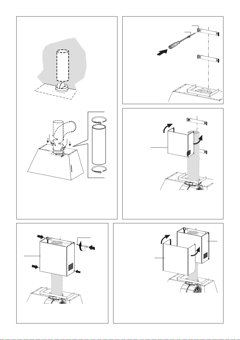
Install the 2
xing brackets
7.2.1 to the
middle and
upper holes
and secure
with screws
12a as
shown.
Install Roof or Wall Cap purchased sepa-
rately. Connect the 6" metal ductwork to the
Roof or Wall Cap and then attach ductwork.
9
8
N1
10 11
12
N1
M1
4x
N2
N1
N
2x
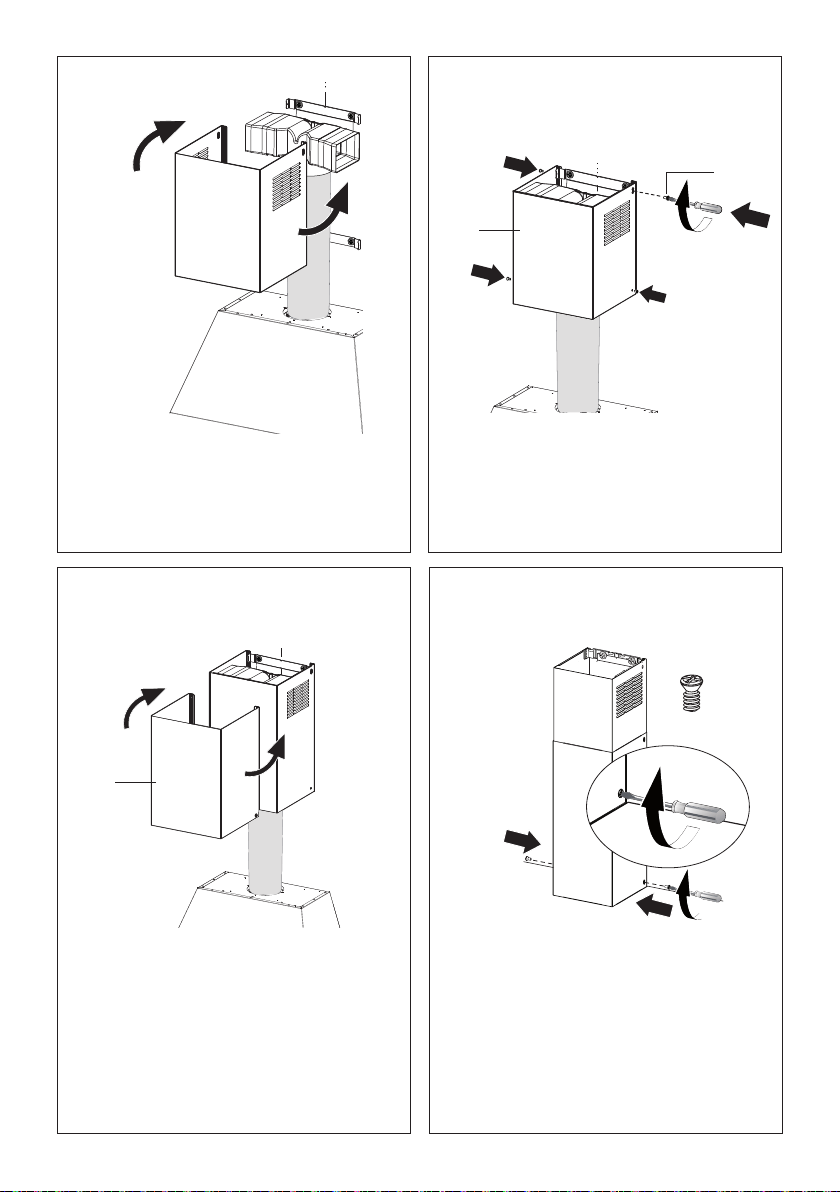
Slightly widen the two sides of the upper
chimney and hook them behind the brackets
7.2.1, making sure that they are well seated.
2.1
Vertical or Horizontal
Ducting Installation
Slightly widen the two sides of the the lower
chimney hood and hook them between the upper
section and the wall, making sure that they are
properly housed.
Secure the sides to the brackets by
using the 4 screws 12b.
10 11
N1
10 11
12
N1
M1
4x
N2
N1
N
2x
2.1
N1
10 11
12
N1
M1
4x
N2
N1
N
2x
2.1
2.2
12b
4x
18
12
N1
10 11
12
N1
M1
4x
N2
N1
N
2x
12e
Fix the the lower chimney hood laterally to the hood body using the 2 screws 12e supplied.

20
20
17
19
Slightly widen the two sides of the upper
chimney and hook them behind the brackets
and connect to the Ductless Diverter, making
sure that they are well seated.
18
Secure the sides to the brackets by using the
4 screws 12b.
Fix the the lower chimney hood laterally to the
hood body using the 2 screws 12e supplied.
Slightly widen the two sides of the the lower
chimney hood and hook them between the
upper section and the wall, making sure that
they are properly housed.
N = 2x
12e
12b
4x
2.1
2.2
21
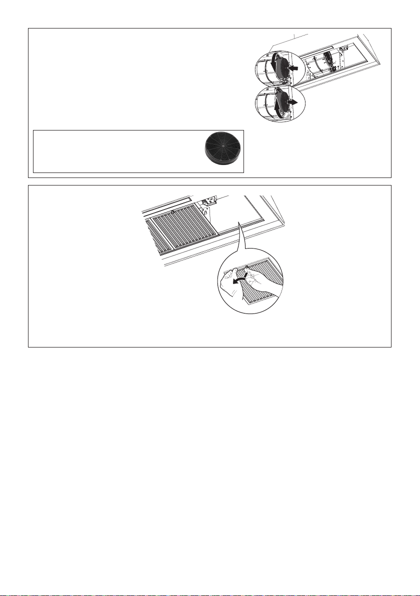
Attach each charcoal lter to the black grid on each side of
the blower. Press the charcoal lter tightly to the black grid
on the blower side and rotate the lter clockwise (towards
the front of the hood) until it locks into place.
Turn counterclockwise (towards the back of the hood) to
remove.
Required Activated Charcoal Filter Accessory
- sku # - FILTER1 (purchased separately).
Long Lasting Charcoal Filter Kit - sku#
FILTER1LL
21
22
Replace the lters one at a time, supporting them with one hand and turning the safety knobs (pull
and turn). Do not discard the lters and set aside for future use.
22
INSTALLATION WITHOUT THE CHIMNEY
Non Ducted - Recirculation Option
1
Draw a vertical line on the supporting wall as high as practical, at the center of the area in which
the hood will be installed. Draw a horizontal line at where the bottom edge of the hood will be
located as indicated in the gure that is a minimum of 24" above Electric cooking surface and 30"
above Gas.
2.a
Draw a horizontal line where indicated above the cooking surface.
Mark the wall at the centers of the holes in the bracket and mark the point 1 and 2 for the Hood
Body installation as shown.
Drill ø 5/16" holes at all the center points marked (point 1,2,3,4) as shown.
KMC30X
KMC30BI
KMC30NE
9 1/16" 9 1/16"
1
3 4
2
30"
10 7/16"
3 15/16"
6 1/2" 6 1/2"
Min.
24"
Min.
30"
Ø 5/16”
x4
x4
3 4
1 2
3 4
1 2
23
2.b
2.c
Draw a horizontal line where indicated above the cooking surface.
Mark the wall at the centers of the holes in the bracket and mark the point 1 and 2 for the Hood
Body installation as shown.
Drill ø 5/16" holes at all the center points marked (point 1,2,3,4,5,6) as shown.
Draw a horizontal line where indicated above the cooking surface.
Mark the wall at the centers of the holes in the bracket and mark the point 1 and 2 for the Hood
Body installation as shown.
Drill ø 5/16" holes at all the center points marked (point 1,2,3,4,5,6) as shown.
KMC36X
KMC36BI
KMC36NE
11"
13
12/16" 13 12/16"
12 3/16" 12 3/16"
1
3 4
2
5
6
10 7/16"
3 15/16"
6 1/2" 6 1/2"
36"
Min.
24"
Min.
30"
Ø 5/16”
x6
x6
5 6
3 4
1 2
5 6
3 4
1 2
10 7/16"11 6/16"
3 8/16"
6 1/2" 6 1/2"
18 14/16" 18 14/16"
17 11/16" 17 11/16"
1
3 4
2
5
6
Ø 5/16”
x6
x6
5 6
3 4
1 2
5 6
3 4
1 2
Min.
24"
Min.
30"
48"
KMC48X
KMC48BI
KMC48NE
24
3
4
Remove the lters one at a time, supporting
them with one hand and turning the safety
knobs (pull and turn).
Do not discard the lters and set aside for future
use.
Hook and x the hood body onto the wall.
From inside fully secure the screws 12a.
5
120
550 min
650 min
120
640
800
Ø 8 mm
4x
I - 4x
6
5
420
L
4x
19
P
P1
2x
20
N
2x
Fix the Recirculation Vent Grill with two screws.
6
12d
2x
8
L
2x
4
3
Z
25
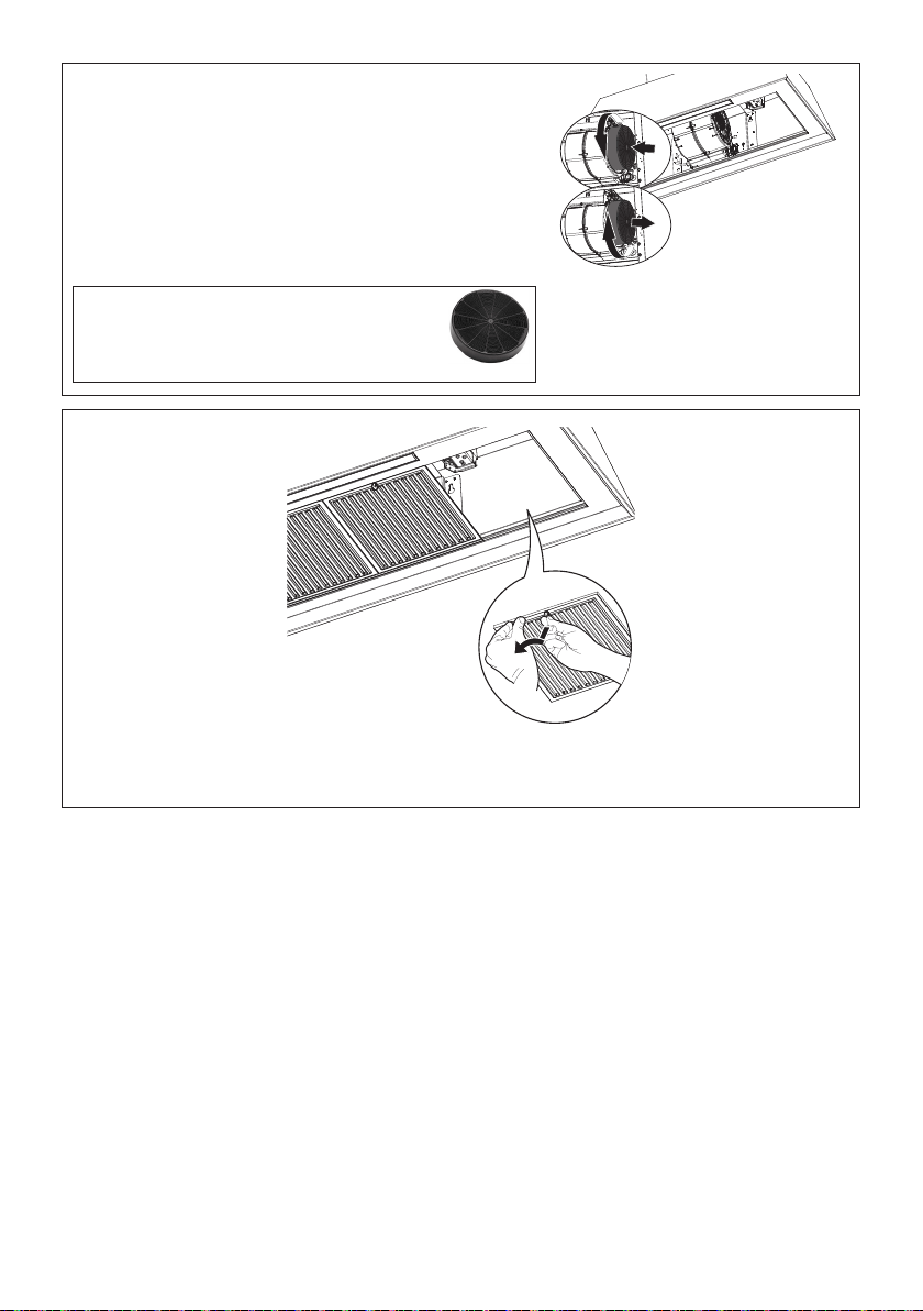
Attach each charcoal lter to the black grid on each side of
the blower. Press the charcoal lter tightly to the black grid
on the blower side and rotate the lter clockwise (towards
the front of the hood) until it locks into place.
Turn counterclockwise (towards the back of the hood) to
remove.
Required Activated Charcoal Filter Accessory
- sku # - FILTER1 (purchased separately).
Long Lasting Charcoal Filter Kit - sku#
FILTER1LL
7
8
Replace the lters one at a time, supporting them with one hand and turning the safety knobs (pull
and turn). Do not discard the lters and set aside for future use.

26
INSTALLATION WITHOUT THE CHIMNEY
Ducted Venting Options Installation
1
Use this dimensional drawing to help with planning of duct connection.
Min.
24"
Min.
30"
7 14/16"
= =
Ø 6"
KMC30X
KMC30BI
KMC30NE
KMC36X
KMC36BI
KMC36NE
KMC48X
KMC48BI
KMC48NE
2
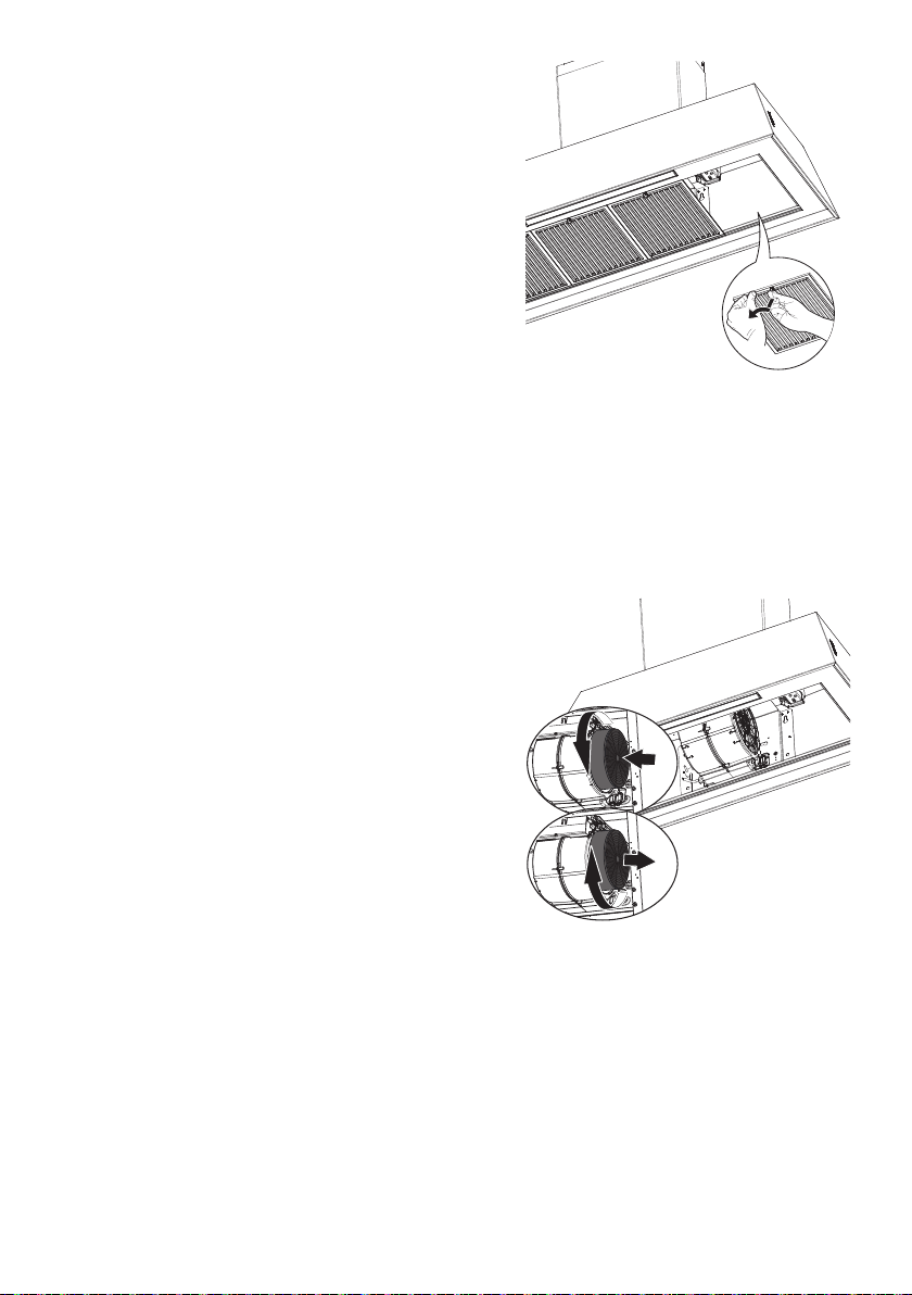
Remove the lters one at a time, supporting them
with one hand and turning the safety knobs (pull and
turn).
Do not discard the lters and set aside for future use.

27
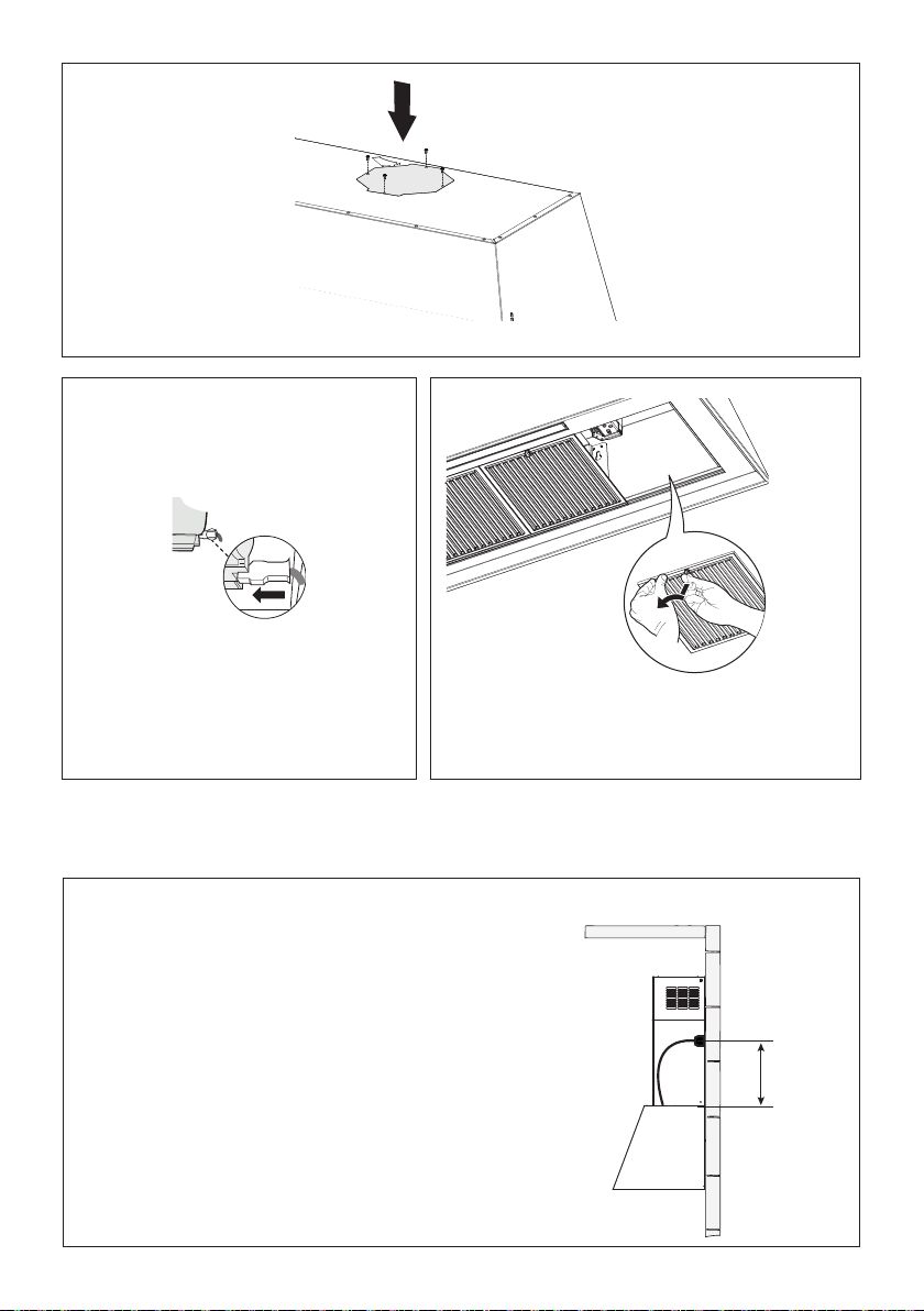
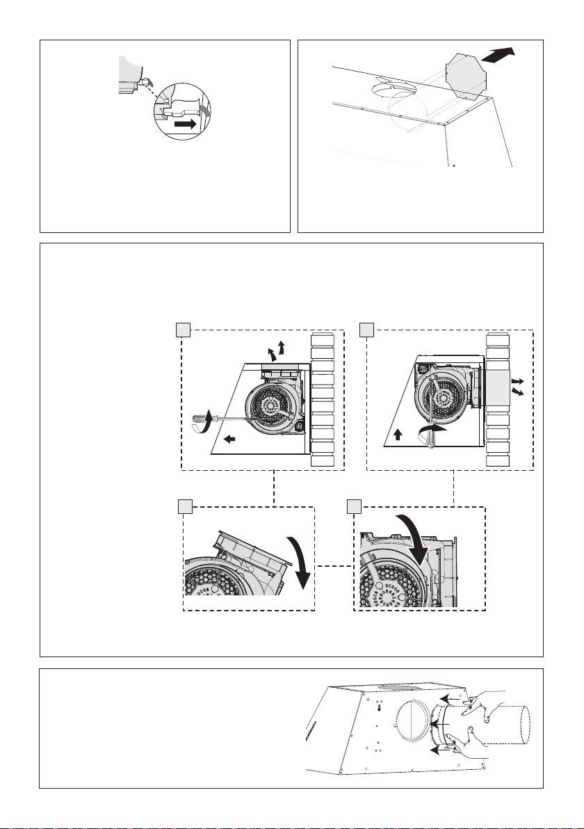
Unscrew the 2 screws
that hold the blower and
unlock it from the initial
position as shown in
Image a.
b c
a d
2x
2x
After removing blower
rotate as shown until
it is in the correct rear
venting position as
shown in Image b-c.
Use the two screws
that were removed to
secure the blower as
shown in Image d.
5
3 4
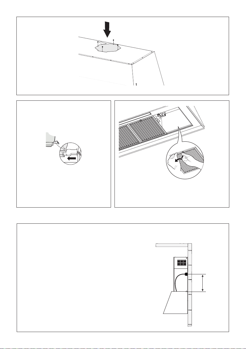
Unscrew the 4 screws that hold the plate and
unlock it from the initial position as shown in
image.
6
Install to the Roof or Wall attach ductwork.
From inside the hood, use the at head
screwdriver as shown in image above, to
disconnect the right Connectors from the blower.
A6
A8
A7
a
b
2x
A9
H=2x
A10
H=2x
Warning! Don't stress the power cable during the blower rotation operation and
carry out the operation in at least two people.
28
7
98
A6
A8
A7
a
b
2x
A9
H=2x
A10
H=2x
From inside the hood re-connect the
Connectors on the right side shown in the
image above.
Replace the lters one at a time, supporting them with
one hand and turning the safety knobs (pull and turn).
Do not discard the lters and set aside for future use.
Use the four screws that were removed to secure the plate as shown in image.
ELECTRICAL INSTALLATION
WITH CONNECTION CABLE
GROUNDING INSTRUCTIONS This appliance must be
grounded. In the event of an electrical short circuit, grounding
reduces the risk of electric shock by providing an escape wire
for the electric current. This appliance is equipped with a cord
having a grounding wire with a grounding plug. The plug must
be plugged into an outlet that is properly installed and grounded.
WARNING - Improper grounding can result in a risk of electric
shock.
Consult a qualied electrician if the grounding instructions are
not completely understood, or if doubt exists as to whether the
appliance is properly grounded.
Do not use an extension cord. If the power supply cord is too short,
have a qualied electrician install an outlet near the appliance.
Max. 33 7/16”
29
USE AND CARE INFORMATION
For Best Results
Start the rangehood several minutes before cooking to develop proper airow. Allow the rangehood to
operate for several minutes after cooking is complete to clear all smoke and odors from the kitchen.
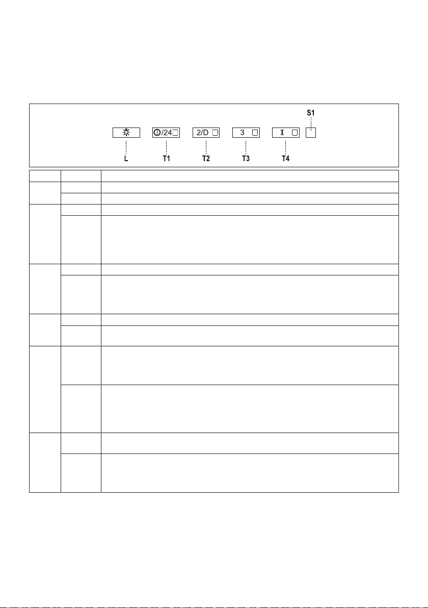
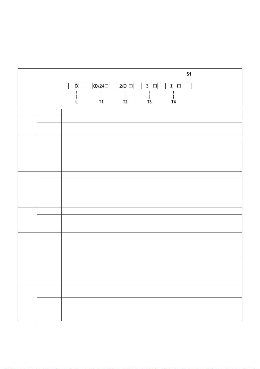
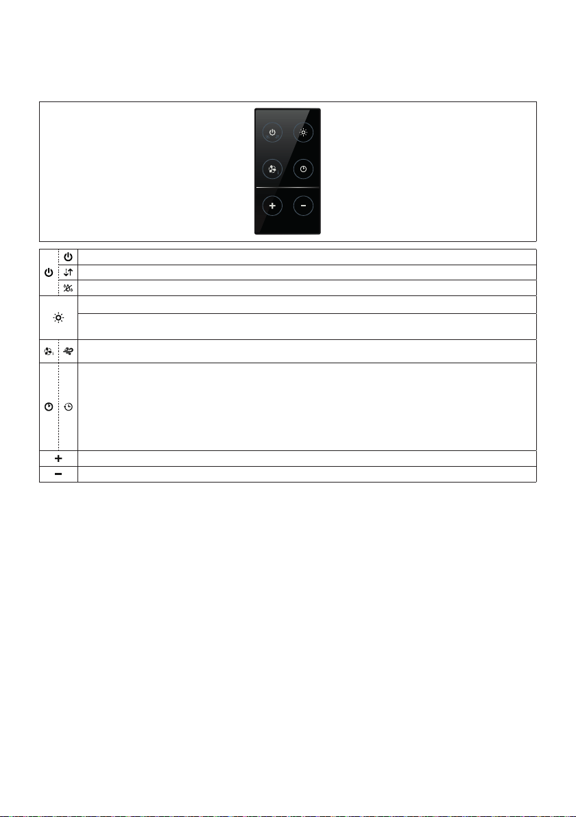
Button Led Function
L - Turns the lights ON/OFF at maximum strength.
- Press and hold for 2sec to turn the Hood lights On/Off at reduced intensity.
T1 Fixed Turns the motor on/off at speed one.
Flashing 24h function:
Press and hold the button for approx. 2 seconds to Activate/Deactivate the motor in
24h Air Circulation mode, a speed that allows ducting for 10 minutes every hour, for a
24 hour cycle.
Cannot be activated if Intensive or Delay modes are active.
T2 Fixed Turns the Motor on at speed two.
Flashing Delay function:
Press and hold the button for approx. 2 seconds to Activate/Deactivate the Delay function
(automatic switching off of the Motor, the Fans and the Lighting with a 30’ delay).
Cannot be enabled when Intensive or 24h are on.
T3 Fixed Turns the Motor on at speed three.
- Press and hold the button for approximately 2 seconds, with all the loads turned off
(Motor and Lights), to reset the Filter saturation alarm. The LED S1 ashes three times.
T4 Flashing Turns the Motor on at Intensive.
Speed.This speed is timed to run for 6 minutes. At the end of this time, the system returns
automatically to the speed that was set before. If it is activated with the motor turned off,
the hood will switch to OFF at the end of the time.
- Press and hold the button for approximately 2 seconds, with all the loads turned off
(Motor and Lights), to turn the Activated Charcoal Filter alarm on. The 4 LEDs on the
buttons ash twice to conrm.
To turn the alarm off, press the button again and hold for at least 5 seconds. The 4 LEDs
on the buttons ash once.
S1 Fixed Signals the Metal Grease Filter saturation alarm, indicating that it is necessary to wash the
lters. The alarm is triggered after the Hood has been in operation for 100 working hours.
Flashing When this is activated, it signals the Activated Charcoal Filter saturation alarm, indicating
that the lter must be changed; the Metal Grease Filters must also be washed. The
Activated Charcoal Filter saturation alarm comes into operation after the Hood has been
working for 200 hours.
30
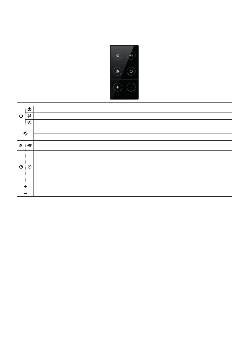
REMOTECONTROL(OPTIONAL)
The remote control is powered by a CR2032 type 3 V battery (not included).
• Do not place the remote control near heat sources.
• Do not discard the batteries with normal waste, they must be put into the specic containers.
Turns the motor On and Off.
-
-
Turns the lights On/Off.
Press and hold for 2sec to turn the Hood lights On/Off at reduced intensity.
Activates/Deactivates Intensive operation.
Brief pressure: Activates/Deactivates the Delay function: automatic switch-off with a 30’ delay. The
display shows the operating speed and the dot at the bottom right ashes once a second.
Press for 2 seconds: Activates/Deactivates the 24h function: turns the suction motor on at speed one
and effects one 10 minute extraction every hour. The display shows the number 24 and the dot at the
bottom right ashes once a second.
Increases the working speed of the motor.
Decreases the working speed of the motor.
31
LED LIGHTING UNIT
• LED lights must be replaced by Faber factory
authorized service.
Cleaning metal grease lters
These can be washed in the dishwasher, and need
to be cleaned whenever the S1 Led comes on or at
least once every 2 months use, or more frequently if
use is particularly intensive.
Resetting the alarm signal
• Turn the Lights and the Suction Motor off.
• Press T3 and hold for at least 3 seconds, until LED
ashes three times in conrmation.
Cleaning
• Remove the lter, pushing the lever towards the back
of the unit and at the same time pulling downward.
• Wash the lter without bending it, leave it to dry
thoroughly before replacing (if the surface of the lter
changes color over time, this will have absolutely
no effect on its efciency).
• Replace, taking care to ensure that the handle
faces forward.
• No water can be present in lters before installing
back in hood.
Replacing Activated Charcoal Filter
This cannot be washed or regenerated, and must
be changed when led S1 starts to ash, or at least
once every 4 months. The Alarm signal, if it has been
activated, only appears when the Suction motor is
turned on.
Resetting the alarm signal
• Turn the Lights and the Suction Motor off.
• Press T3 and hold for at least 3 seconds, until LED
ashes three times in conrmation.
Cleaning
• Remove the charcoal lter by rotating it clockwise
(backwards) until it unlocks from the motor housing
and pull off sideways.
• To re-insert each charcoal lter, place up against
the side of the blower and push it inward. Then
turn the charcoal lter clockwise (forward) until it
ts into place.
• CAUTION: When used in recirculation mode, to
Reduce the Risk of Fire and Shock use only con-
version kit Model FILTER 1 or FILTER1LL.

32
Wiring Diagram
0 1 2 3 4 5 6 7 8 9
H90_309
02
Drawing N : Rev :
Modif. by
Doc.status
Do not get quotas from the drawing do not bring
modifications without authorization of techincal office.
According to the law we reserve the own of the present
drawing with reproduction prohibition partial or total.
Approved date
Modification description
Approved by
WIRING DIAGRAM M8-4V ATF LED UL
Doc Type
Denomination
Creation date
18.Apr.2019
DOLCE CORRADO
Created by
991.0454.388
Code
BRWY-G
GRY
123
654
789
123
654
987
RED
WHT
BLU
BLU
BRW
M8-4V
BLU
BLK
ORG
ORG
PNK
7
BRW
MOTOR
6
GRY
5
ORG
4
BLU
3
PNK
F
2
WHT
LINE
120Vac 60Hz
1
BLK
N
FLAT CABLE
LUX2
2
L-B
1
Y-G
BRW
BLK
WHT
GRY
WHT
GRY
BLK
AUX
Faber ATF
2
Y-G
1
LUX1
SEC.
- +
ELECTRONIC
TRNSFORMER
L N
2
ORG(red)
1
ORG(vlt)
FLAT CABLE
GRY (red)
BLK (vlt)
1
2
12
12
GRYGRYGRY
1
LED
BLKBLKBLK
2
1
2
12
GRYGRY
LED
BLKBLK
1
2
12
GRYGRY
LED
BLKBLK
1
2
12
GRYGRY
LED
BLKBLK
BARRA FARETTO LED
12
GRY
BLK
12
BARRA FARETTO LED

33
January 4, 2016
FABER CONSUMER WARRANTY & SERVICE
All Faber products are warranted against any defect in materials or workmanship for the original purchaser
for a period of 1 year from the date of original purchase (requires proof of purchase). This warranty covers
labor and replacement parts. Faber, at its option, may repair or replace the product or components
necessary to restore the product to good working condition. To obtain warranty service, contact the dealer
from whom you purchased the range hood, or the local Faber distributor. If you cannot identify a local Faber
distributor, contact us at (508) 358-5353 for the name of a distributor in your area.
The following is not covered by Faber's warranty:
1. Service calls to correct the installation of your range hood, to instruct you how to use your range hood, to
replace or repair house fuses or to correct house wiring or plumbing.
2. Service calls to repair or replace range hood light bulbs, fuses or filters. Those consumable parts are
excluded from warranty coverage.
3. Repairs when your range hood is used for other than normal, single-family household use.
4. Damage resulting from accident, alteration, misuse, abuse, fire, flood, acts of God, improper installation,
installation not in accordance with electrical or plumbing codes or Faber documentation, or use of products
not approved by Faber.
5. Replacement parts or repair labor costs for units operated outside the United States or Canada, including
any non-UL or C-UL approved Faber range hoods.
6. Repairs to the hood resulting from unauthorized modifications made to the range hood.
7. Expenses for travel and transportation for product service in remote locations and pickup and delivery
charges. Faber range hoods should be serviced in the home.
THIS WARRANTY DOES NOT ALLOW RECOVERY OF INCIDENTAL OR CONSEQUENTIAL DAMAGES, INCLUDING, WITHOUT
LIMITATION, DIRECT, INDIRECT, INCIDENTAL, SPECIAL OR CONSEQUENTIAL DAMAGES, PERSONAL INJURY/WRONGFUL
DEATH OR LOST PROFITS FABER WARRANTY IS LIMITED TO THE ABOVE CONDITIONS AND TO THE WARRANTY PERIOD
SPECIFIED HEREIN AND IS EXCLUSIVE. EXCEPT AS EXPRESSLY SPECIFIED IN THIS AGREEMENT, FABER DISCLAIMS ALL
EXPRESS OR IMPLIED CONDITIONS, REPRESENTATIONS, AND WARRANTIES INCLUDING, WITHOUT LIMITATION, ANY
IMPLIED WARRANTIES OF MERCHANTABILITY OR FITNESS FOR A PARTICULAR PURPOSE
.
This warranty gives you specific legal rights that may vary from state to state.
Model#: ______________________________ Serial #: _____________________________

34
VEUILLEZ LIRE ET CONSERVER LA PRÉSENTE NOTICE AVANT DE
COMMENCER L'INSTALLATION DE LA HOTTE DE CUISINE
AVERTISSEMENT:POURRÉDUIRELERISQUED'UNFEUDEGRAISSESURLATABLEDECUISSON:
a) Ne laissez jamais sans surveillance les éléments de la surface de cuisson à température élevée. Les
bouillonnements excessifs peuvent provoquer de la fumée et les débordements de graisse peuvent
s'enammer.L'huiledoitêtrechaufféelentement,àunetempératurebasseoumoyenne.
b) Assurez-vous de toujours mettre en marche le ventilateur de la hotte lorsque vous cuisinez à tem-
pératureélevéeoupréparezunmetsambé(p.ex.crêpesSuzette,cerisesjubilé,bœufambé).
c) Nettoyez régulièrement les ventilateurs d'aspiration. Assurez-vous de ne pas laisser de la graisse
s'accumulersurleventilateurouleltre.
d)Utiliseztoujoursdespoêlesetcasserolesdelatailleappropriée.Utiliseztoujoursdesustensilesde
cuisine de la taille adaptée à celle de l'élément chauffant.
AVERTISSEMENT:-POURPRÉVENIRLESBLESSURESENCASDEFEUDEGRAISSESURLATABLE
DECUISSON,SUIVEZLESRECOMMANDATIONSSUIVANTES*:
a) ÉTOUFFEZ LES FLAMMES à l'aide d'un couvercle hermétique, d'une plaque à biscuits ou d'un plateau
métallique, puis éteignez le brûleur. FAITES ATTENTION AUX BRÛLURES. Si le feu ne s'éteint pas
immédiatement, QUITTEZ LES LIEUX ET APPELEZ LES POMPIERS.
b) NE PRENEZ JAMAIS UNE CASSEROLE EN FLAMME - Vous pourriez vous brûler.
c) N'UTILISEZ JAMAIS DE L'EAU, ni un linge à vaisselle ou un torchon mouillé, pour éteindre le feu. Cela
pourrait provoquer une violente explosion de vapeur.
d)UtilisezunextincteurUNIQUEMENTsi:
1. Vousêtescertainqu'ils'agitd'unextincteurdeclasseABCetquevousconnaissezbienson
mode d'emploi.
2. Le feu est de faible intensité et se limite à l'endroit où il a démarré.
3. Les pompiers ont déjà été appelés.
4. Unevoiedesortiesetrouvederrièrevouspendantquevouséteignezlesammes.
* D'après le guide «Kitchen Firesafety Tips» publié par la NFPA aux États-Unis
AVERTISSEMENT - POUR RÉDUIRE LE RISQUE D'INCENDIE OU DE CHOC ÉLECTRIQUE, n'utilisez
jamais ce ventilateur en association avec un dispositif de réglage de vitesse à semi-conducteurs.
AVERTISSEMENT - POUR RÉDUIRE LES RISQUES D'INCENDIE, DE CHOC ÉLECTRIQUE OU DE
BLESSURECORPORELLE,RESPECTEZLESINSTRUCTIONSSUIVANTES:
1. Utilisez cet appareil uniquement de la façon prévue par le fabricant. Pour toute question, commu-
niquez avec le fabricant.
2. Avant de procéder à l'entretien ou au nettoyage de l'appareil, coupez l'alimentation au niveau du
panneau électrique et verrouillez-le pour vous assurer que l'électricité n'est pas rétablie accidentel-
lement.S'iln'estpaspossibledeverrouillerledispositifd'interruptiondel'alimentation,afchezde
façon ferme et bien visible un avis de danger, par exemple à l'aide d'une étiquette sur le panneau.
ATTENTION:Destinéàunusagedeventilationgénéraleuniquement.N'utilisezpascedispositifpour
l'aspiration de vapeurs ou de matériaux dangereux ou explosifs.
AVERTISSEMENT - POUR RÉDUIRE LES RISQUES D'INCENDIE, DE CHOC ÉLECTRIQUE OU DE
BLESSURECORPORELLE,RESPECTEZLESINSTRUCTIONSSUIVANTES:
1. L'installationetlebranchementélectriquedoiventêtreréalisésparuntechnicienqualiéetcon-
formément à tous les codes et normes en vigueur, incluant ceux concernant la construction à
l'épreuve du feu.
2. Andegarantirunecombustionetuneévacuationadéquatesdesgazparlesconduitesdelache-
minée des appareils à combustion, une bonne aération est nécessaire pour éviter le refoulement.
Respectez les lignes directrices fournies par le fabricant du matériel chauffant, ainsi que les normes
desécuritécommecellespubliéesparlaNationalFireProtectionAssociation(NFPA)etlaAmerican
SocietyforHeating,RefrigerationandAirConditioningEngineers(ASHRAE)auxÉtats-Unis,ainsi
que les codes en vigueur dans votre région.
3. Lorsque vous faites une ouverture ou percez dans un mur ou le plafond, veillez à ne pas endom-
magerleslsélectriquesoud'autresdispositifscachés.
4. Lesventilateurscanalisésdoiventtoujoursêtreraccordésàl'extérieur.
35
TOUTE OUVERTURE DANS LE MUR OU LE PLANCHER À PROXIMITÉ DE LA HOTTE DOIT
ÊTRE SCELLÉE.
Un espace libre d'au moins 24" est requis entre le bas de la hotte et la surface de cuisson ou le
comptoir. Cette hotte a été homologuée par l'UL à cette distance de la surface de cuisson.
L’espace libre minimal requis peut-être plus grand, selon la réglementation en matière de construction
de votre région. Pour les cuisinières à gaz et les cuisinières combinées, un espace minimal de 30" est
recommandé et pourrait être exigé.
Les armoires suspendues de chaque côté de l'appareil doivent se trouver à au moins 18" de la surface
de cuisson ou du comptoir. Consultez la notice d'installation de la surface de cuisson ou de la cuisinière
fournie par le fabricant avant de pratiquer des ouvertures.
INSTALLATION DANS UNE MAISON MOBILE L'installation de cette hotte doit être conforme à la Partie
3280 de la norme Manufactured Home Construction and Safety Standards, Title 24 CFR (précédemment
la partie 280 de la norme Federal Standard for Mobile Home Construction and Safety, Title 24, HUD).
Consultez la che technique électrique.
CRITÈRES DE VENTILATION
Déterminez quelle méthode de ventilation est mieux adaptée à votre application. Les conduits peuvent
passer par le mur ou le toit.
Pour garantir une meilleure efcacité, la longueur des conduits et le nombre de coudes doivent être le
plus limités que possible. Le diamètre des conduits devrait être uniforme. N'installez pas deux coudes
ensemble. Utilisez un ruban pour canalisations an de sceller tous les joints du système de conduits.
Utilisez un calfeutrage pour sceller les ouvertures dans le mur extérieur ou le plancher, autour du clapet.
Iln'estpasrecommandéd'utiliserdesconduitsexibles.Lesconduitsexiblesprovoquent
unecontre-pressionetdelaturbulencequidiminuentgrandementl'efcacitédel'appareil.
Assurez-vous que l'espace libre dans le mur ou le plancher est sufsant pour le conduit d'évacuation
avant de pratiquer les ouvertures. Ne coupez jamais une poutre ou un chevron, sauf si c'est absolument
nécessaire. S'il s'avère nécessaire de couper une poutre ou un chevron, la construction d'un renforce-
ment est requise.
AVERTISSEMENT - Pour réduire le risque d'incendie, utilisez uniquement des conduits métall-
iques.
ATTENTION - Pour réduire le risque d'incendie et pour évacuer adéquatement l'air, assurez-vous
deraccorderlesconduitsàl'extérieur–Nediffusezpasl'aird'évacuationdansdesespacesà
l'intérieur des murs ou du plafond, ou encore à l'intérieur d'un grenier, d'une galerie technique
ou d'un garage.
• Le système de ventilation DOIT déboucher à l'extérieur.
• NE FAITES PAS déboucher les conduits dans un grenier ou un autre endroit fermé.
• N'UTILISEZ PAS un clapet de sécheuse mural de 4" .
• Il n'est pas recommandé d'utiliser des conduits exibles.
• N'ENTRAVEZ PAS le ux de l'air de combustion et de ventilation.
• Le non-respect des exigences en matière de ventilation pourrait entraîner un incendie.
AVERTISSEMENT
!
Installation dans les climats froids
Le système de ventilation doit prévoir un registre antirefoulement supplémentaire pour réduire le
ux d'air froid inverse, ainsi qu'une barrière thermique non métallique pour réduire la conduction
des températures extérieures. Le registre doit être installé du côté air froid par rapport à la barrière
thermique. La barrière thermique doit être positionnée le plus près que possible de l'endroit où le
système de ventilation pénètre dans la partie chauffée de la maison.
36
• Une mise à la terre électrique est requise pour cette hotte.
• N'UTILISEZ PAS un tuyau d'eau froide pour la mise à la terre si celui-ci est branché par des
joints en plastique, par des rondelles non métalliques ou d'autres matériaux.
• N'UTILISEZ PAS une conduite de gaz pour la mise à la terre.
• N'INSTALLEZ PAS un fusible sur le circuit neutre ou le circuit de mise à la terre. La présence
d'un fusible dans le circuit neutre ou de mise à la terre peut entraîner un choc électrique.
• Consultez un électricien qualié si vous n'êtes pas certain de la mise à la terre de la hotte.
• Le non-respect des exigences de la che technique électrique pourrait entraîner un incendie.
AVERTISSEMENT
!
Avertissementdelaproposition65del'ÉtatdeCalifornie(USseulement)
ATTENTION
Ce produit contient des produits chimiques connus de l'État de Californie pour causer le
cancer et des malformations congénitales ou d'autres problèmes de reproduction.
Pour plus d'informations, visitez www.P65Warnings.ca.gov
FICHE TECHNIQUE ÉLECTRIQUE
Une alimentation de courant alternatif de 120 volt à 60 Hz est requise sur un circuit à fusible distinct
de 15 ampères. Il est recommandé d'installer un fusible temporisé ou un disjoncteur. Le fusible doit
être calibré conformément aux codes en vigueur pour les caractéristiques nominales électriques
de l'appareil, indiquées sur la plaque signalétique située à l'intérieur de l'appareil, à proximité du
compartiment des câblages externes.

37
DIMENSIONS DE LA HOTTE
KMC30X
KMC30BI
KMC30NE
KMC36X
KMC36BI
KMC36NE
KMC48X
KMC48BI
KMC48NE
18-1/16''
11-13/16''
7-7/8''
20-1/2 ''
MIN AS 21-7/8''- MAX ASP 36''
MIN REC 25-3/8''- MAX REC 39-15/16''
12-5/8''
29-7/8'' - 35-13/16''
Created by
Latini, Francesco
Denomination
DIMENSIONAL DRAWING 30-36''
Lang EN
Sheet
1
/2
Modif.by
Approved by
Approval date
Doc. status
Drawing N.
321033_724
Rev
01
47-7/8''
18-1/16''
15-3/4
''
7-7/8''
20-1/2''
MIN 21-7/8''-MAX 39-15/16''
12-5/8 ''
Created by
Latini, Francesco
Denomination
DIMENSIONAL DRAWING 48''
Lang EN
Sheet
1
/2
Modif.by
Approved by
Approval date
Doc. status
Drawing N.
321033_734
Rev
01
38
Min. 24" Min. 30"
39
PIÈCES PRINCIPALES
KMC30X - KMC30BI - KMC30NE
Composants
Réf. Qté. Composants du produit
1 1 Bâti de la hotte avec : Commandes,
Éclairage, Filtres, Ventilateur.
2 1 Cheminée télescopique, comprenant:
2.1 1 Section supérieure
2.2 1 Section inférieure
3 1 Équerre de xation
10 1 Registre ø 5 7/8"
10e 1 Raccord de soutien pour recyclage
9 1 Raccord de recyclage, comprenant:
9.1 1 Raccord de recyclage
9.2 1 Intermédiaire de raccord de recyclage
9.3 1 Intermédiaire de raccord de recyclage
8 1 Grille d'évent de recyclage
Réf. Qté. Composants d’installation
7.2.1 2 Brides de xation de section cheminée
supérieure
12a 8 Vis 3/16" x 1 15/16"
12b 4 Vis 1/8" x 3/8"
12d 6 Vis 1/8" x 1/4"
12e 2 Vis 1/8" x 3/8"
12f 2 Vis 1/8" x 1/2"
Qté. Documentation
1 Mode d’emploi
10e
9.2
9.1
9.3
10
12e
12d
12b
12a
8
1
2.1
2.2
7.2.1
3
12f
Accessoires disponibles
- Trousse d'évent de recyclage - Filtre à
charbon actif - no d’article FILTER1
- Trousse ltre à charbon lavable longue
durée - no d’article FILTER1LL
- Télécommande sans l accessoire -
REMCTRL2
Pièces requises
- Conduit métallique circulaire 6"

40
PIÈCES PRINCIPALES
KMC36X - KMC36BI - KMC36NE
10e
9.2
9.1
9.3
10
12e
12d
12b
12a
8
1
2.1
2.2
7.2.1
3
12f
Composants
Réf. Qté. Composants du produit
1 1 Bâti de la hotte avec : Commandes,
Éclairage, Filtres, Ventilateur.
2 1 Cheminée télescopique, comprenant:
2.1 1 Section supérieure
2.2 1 Section inférieure
3 1 Équerre de xation
10 1 Registre ø 5 7/8"
10e 1 Raccord de soutien pour recyclage
9 1 Raccord de recyclage, comprenant:
9.1 1 Raccord de recyclage
9.2 1 Intermédiaire de raccord de recyclage
9.3 1 Intermédiaire de raccord de recyclage
8 1 Grille d'évent de recyclage
Réf. Qté. Composants d’installation
7.2.1 2 Brides de xation de section cheminée
supérieure
12a 10 Vis 3/16" x 1 15/16"
12b 4 Vis 1/8" x 3/8"
12d 6 Vis 1/8" x 1/4"
12e 2 Vis 1/8" x 3/8"
12f 2 Vis 1/8" x 1/2"
Qté. Documentation
1 Mode d’emploi
Accessoires disponibles
- Trousse d'évent de recyclage - Filtre à
charbon actif - no d’article FILTER1
- Trousse ltre à charbon lavable longue
durée - no d’article FILTER1LL
- Télécommande sans l accessoire -
REMCTRL2
Pièces requises
- Conduit métallique circulaire 6"

41
PIÈCES PRINCIPALES
KMC48X - KMC48BI - KMC48NE
10
12e
12d
12b
12a
8
1
2.1
2.2
7.2.1
3
Composants
Réf. Qté. Composants du produit
1 1 Bâti de la hotte avec : Commandes,
Éclairage, Filtres, Ventilateur.
2 1 Cheminée télescopique, comprenant:
2.1 1 Section supérieure
2.2 1 Section inférieure
3 1 Équerre de xation
10 1 Registre ø 5 7/8"
8 1 Grille d'évent de recyclage
Réf. Qté. Composants d’installation
7.2.1 2 Brides de xation de section cheminée
supérieure
12a 10 Vis 3/16" x 1 15/16"
12b 4 Vis 1/8" x 3/8"
12d 6 Vis 1/8" x 1/4"
12e 2 Vis 1/8" x 3/8"
Qté. Documentation
1 Mode d’emploi
Accessoires disponibles
- Trousse d'évent de recyclage - Filtre à
charbon actif - no d’article FILTER1
- Trousse ltre à charbon lavable longue
durée - no d’article FILTER1LL
- Télécommande sans l accessoire -
REMCTRL2
Pièces requises
- Conduit métallique circulaire 6"
42
Option sans canalisation, avec recyclage d’air
Exige
l'achat de
l'accessoire
à charbon
actif.
Horizontal
Vertical
44
51
6"
6"
Choisissez la méthode de canalisation
INSTALLATION AVEC CHEMINÉE
Installation avec ventilation canalisée
43
Choisissez la méthode de canalisation
INSTALLATION SANS CHEMINÉE
Option sans canalisation,
avec recyclage d’air
Exige l'achat de l'accessoire à charbon actif.
Pour réduire le risque d’incendie ou de choc
électrique lorsque l’appareil est en mode
recyclage, utilisez uniquement les trousses
de conversion FILTER1 ou FILTER1LL.
Options d'installation avec
ventilation canalisée
6"
Horizontal
5854
44
1
Tracez une ligne verticale sur le mur d'appui le plus haut que possible, au centre de l'emplacement
où la hotte sera installée.
Tracez une ligne horizontale à l'endroit correspondant au bas de la hotte comme représenté dans
l'illustration. Cet emplacement doit se trouver à une distance de 24" de la surface de cuisson au
minimum si elle est électrique, et de 30" au minimum si elle est au gaz.
Notice d'installation
Installez le registre inclus avec la hotte avant
de la raccorder aux conduits.
Pour installation avec ventilation canalisée uniquement
H
I

45
2.a
Tracez un repère sur le mur à l'endroit indiqué, 10 7/16" au-dessus de la ligne horizontale et à 6 1/2"
de la ligne verticale, à droite et à gauche de cette dernière. Vériez si les deux repères sont à niveau.
Insérez deux chevilles et deux vis dans les orices comme illustré, pas complètement (achetées
séparément).
Tracez un repère sur le mur à l'endroit indiqué, 3 15/16" au-dessus de la ligne horizontale et à 9 1/16"
de la ligne verticale, à droite et à gauche de cette dernière. Vériez si les deux repères sont à niveau.
Insérez deux chevilles (achetées séparément).
Placez une bride 7.2.1 sur le mur comme illustré, à environ 1 1/8" du plafond ou de la limite supérieure,
en alignant le centre (encoche) avec la ligne de référence verticale. Marquez l'emplacement du centre
des trous du support sur le mur.
Placez la deuxième bride 7.2.1 sur le mur comme illustré, sous la première bride, à la hauteur de la section
supérieure de la cheminée fournie. Alignez les centres (encoche) avec la ligne verticale.
Tracez un repère sur le mur, au centre des trous de la bride et percez des trous de ø 5/16" comme illustré.
Les vis d'installation fournies pour les brides doivent être renforcées par des chevilles (achetées séparément).
10 7/16"
3 15/16"
6 1/2" 6 1/2"
9 1/16" 9 1/16"
1 1/8”
>
Ø 5/16”
Min.
24"
2.1
Min.
30"
2.1
x8
7.2.1
x8
1
5 6
7 8
7 8
5 6
3 4
1 2
3 4
2
7 8
5 6
3 4
1 2
30"
KMC30X
KMC30BI
KMC30NE
46
2.b
Tracez un repère sur le mur à l'endroit indiqué, 10 7/16" au-dessus de la ligne horizontale et à 6 1/2"
de la ligne verticale, à droite et à gauche de cette dernière. Vériez si les deux repères sont à niveau.
Insérez deux chevilles et deux vis dans les orices comme illustré, pas complètement (achetées
séparément).
Tracez un repère sur le mur à l'endroit indiqué, 3 15/16" au-dessus de la ligne horizontale et à 13 12/16"
de la ligne verticale, à droite et à gauche de cette dernière. Vériez si les deux repères sont à niveau.
Insérez deux chevilles (achetées séparément).
Tracez un repère sur le mur à l'endroit indiqué, 11" au-dessus de la ligne horizontale et à 12 3/16" de la
ligne verticale, à droite et à gauche de cette dernière. Vériez si les deux repères sont à niveau.
Insérez deux chevilles (achetées séparément).
Placez une bride 7.2.1 sur le mur comme illustré, à environ 1 1/8" du plafond ou de la limite supérieure,
en alignant le centre (encoche) avec la ligne de référence verticale. Marquez l'emplacement du centre
des trous du support sur le mur.
Placez la deuxième bride 7.2.1 sur le mur comme illustré, sous la première bride, à la hauteur de la section
supérieure de la cheminée fournie. Alignez les centres (encoche) avec la ligne verticale.
Tracez un repère sur le mur, au centre des trous de la bride et percez des trous de ø 5/16" comme illustré.
Les vis d'installation fournies pour les brides doivent être renforcées par des chevilles (achetées séparément).
KMC36X
KMC36BI
KMC36NE
10 7/16"11"
3
15/16"
6 1/2" 6 1/2"
13 12/16" 13 12/16"
12 3/16" 12 3/16"
1 1/8”
>
Ø 5/16”
Min.
24"
Min.
30"
2.1
2.1
7.2.1
x10
x10
1
9 10
7 8
3 4
2
9 10
7 8
5 6
3 4
1 2
9 10
7 8
5 6
3 4
1 2
5
6
36"
47
2.c
Tracez un repère sur le mur à l'endroit indiqué, 10 7/16" au-dessus de la ligne horizontale et à 6 1/2"
de la ligne verticale, à droite et à gauche de cette dernière. Vériez si les deux repères sont à niveau.
Insérez deux chevilles et deux vis dans les orices comme illustré, pas complètement (achetées
séparément).
Tracez un repère sur le mur à l'endroit indiqué, 3 15/16" au-dessus de la ligne horizontale et à 18 14/16"
de la ligne verticale, à droite et à gauche de cette dernière. Vériez si les deux repères sont à niveau.
Insérez deux chevilles (achetées séparément).
Tracez un repère sur le mur à l'endroit indiqué, 11 6/16" au-dessus de la ligne horizontale et à 11 11/16"
de la ligne verticale, à droite et à gauche de cette dernière. Vériez si les deux repères sont à niveau.
Insérez deux chevilles (achetées séparément).
Placez une bride 7.2.1 sur le mur comme illustré, à environ 1 1/8" du plafond ou de la limite supérieure,
en alignant le centre (encoche) avec la ligne de référence verticale. Marquez l'emplacement du centre
des trous du support sur le mur.
Placez la deuxième bride 7.2.1 sur le mur comme illustré, sous la première bride, à la hauteur de la section
supérieure de la cheminée fournie. Alignez les centres (encoche) avec la ligne verticale.
Tracez un repère sur le mur, au centre des trous de la bride et percez des trous de ø 5/16" comme illustré.
Les vis d'installation fournies pour les brides doivent être renforcées par des chevilles (achetées séparément).
KMC48X
KMC48BI
KMC48NE
10 7/16"
3 15/16"
6 1/2" 6 1/2"
1 1/8”
>
Ø 5/16”
Min.
24"
Min.
30"
2.1
2.1
7.2.1
x10
x10
5 6
7 8
9 10
7 8
5 6
3 4
1 2
9 10
7 8
5 6
3 4
1 2
11 6/16"
18 14/16"
18 14/16"
11 11/16" 11 11/16"
1
3 4
2
5
6
48"
48
3
4
Retirez les ltres un à un, en les soutenant d’une
main et en tournant les boutons de sécurité (tirez
vers vous et tournez).
Ne jetez pas les ltres, mais conservez-les pour
plus tard.
Engagez et xez le bâti de la hotte
sur le mur.
INSTALLATION AVEC CHEMINÉE
OK!
3/16”
L
2x
4
3
Z
120
550 min
650 min
120
640
800
Ø 8 mm
4x
I - 4x
6
5
420
L
4x
Utilisez les quatre vis pour xer l’étrier
d’assemblage.
Depuis l’intérieur, vissez à fond les vis 12a.
5 6
3
12d
4x
49
7
9
Ø 150
O
Ø 120
8
L
4x
M
2x
7
O1
N
4x
Installez les 2
brides de xation
7.2.1 à l'aide des
trous percés au
milieu et au haut,
et xez-les à
l'aide de vis 12a
comme illustré.
Installez le clapet de toiture ou le clapet
mural acheté séparément. Raccordez le
conduit métallique de 6" au clapet de toiture
ou au clapet mural, puis raccordez les
conduits.
9
8
N1
10 11
12
N1
M1
4x
N2
N1
N
2x
Écartez légèrement les deux côtés de la
cheminée supérieure et engagez-les derrière
les brides 7.2.1, en vous assurant qu'ils sont
solidement ancrés.
2.1
Installation avec canalisation
vertical ou horizontal
Écartez légèrement les deux côtés de la section
inférieure et assemblez-les entre la section
supérieure et le mur, en vous assurant qu'ils sont
correctement installés.
Fixez les côtés aux brides à l'aide des
4 vis 12b.
10 11
N1
10 11
12
N1
M1
4x
N2
N1
N
2x
2.1
N1
10 11
12
N1
M1
4x
N2
N1
N
2x
2.1
2.2
12b
4x

50
12
N1
10 11
12
N1
M1
4x
N2
N1
N
2x
12e
Fixez la section inférieure de la cheminée de hotte latéralement sur le bâti de la hotte à l'aide des
2 vis 12e fournies.
51
Fixez la bride 7.2.1 inférieure à l'aide de deux
vis 12a fournies, comme illustré.
Pour la version à recirculation d'air
uniquement, branchez la hotte à la sortie
d'air.
13 14
Option non canalisée avec
recirculation d'air
1
3
2
10e
12f
2x
9.2
9.1
9.3
15
Fixez le déecteur de recyclage à l'aide de
deux vis 12f fournies, comme illustré.
16
Fixez le déecteur de recyclage à l'aide de
deux vis 12a fournies, comme illustré.
1
3
2
10e
12f
2x
9.2
9.1
9.3
52
20
17
19
Écartez légèrement les deux côtés de la
cheminée supérieure et engagez-les derrière
les brides, et raccordez le déecteur de
recyclage, en vous assurant qu'ils sont
solidement ancrés.
18
Fixez les côtés aux brides à l'aide des 4 vis
12b.
Fixez les côtés aux brides à l'aide des 4 vis
12e.
Écartez légèrement les deux côtés de la
cheminée supérieure et engagez-les derrière
les brides, et raccordez le déecteur de
recyclage, en vous assurant qu'ils sont
solidement ancrés.
N = 2x
12e
12b
4x
2.1
2.2
53
Fixez les ltres à charbon à la grille noire de chaque côté
du ventilateur. Pressez fermement le ltre à charbon
contre la grille noire de chaque côté du ventilateur et faites
tourner le ltre dans le sens des aiguilles d'une montre
(vers l'avant de la hotte) jusqu'à ce qu'il soit verrouillé en
place. Faites tourner dans le sens contraire des aiguilles
d'une montre (vers l'arrière de la hotte) pour l'enlever.
Filtre à charbon actif accessoire requis - no
d'article - FILTER1 (acheté séparément).
Trousse ltre à charbon longue durée - no
d’article FILTER1LL
21
22
Remettez en place les ltres un à un, en les soutenant d’une main et en tournant les boutons de
sécurité (tirez vers vous et tournez). Ne jetez pas les ltres, mais conservez-les pour plus tard.

54
INSTALLATION SANS CHEMINÉE
Option sans canalisation, avec recyclage d’air
1
Tracez une ligne verticale sur le mur d'appui le plus haut que possible, au centre de l'emplacement
où la hotte sera installée. Tracez une ligne horizontale à l'endroit correspondant au bas de la hotte
comme représenté dans l'illustration. Cet emplacement doit se trouver à une distance de 24" de
la surface de cuisson au minimum si elle est électrique, et de 30" au minimum si elle est au gaz.
2.a
Tracez une ligne horizontale à la distance indiquée au-dessus de la surface de cuisson.
Tracez un repère sur le mur, au centre des trous de la bride et à l'emplacement des points 1 et 2
pour l'installation du bâti de la hotte, comme illustré.
Percez des trous de ø 5/16" au centre des repères (points 1, 2, 3, 4), comme illustré.
KMC30X
KMC30BI
KMC30NE
9 1/16" 9 1/16"
1
3 4
2
30"
10 7/16"
3 15/16"
6 1/2" 6 1/2"
Min.
24"
Min.
30"
Ø 5/16”
x4
x4
3 4
1 2
3 4
1 2

55
2.b
2.c
Tracez une ligne horizontale à la distance indiquée au-dessus de la surface de cuisson.
Tracez un repère sur le mur, au centre des trous de la bride et à l'emplacement des points 1 et 2
pour l'installation du bâti de la hotte, comme illustré.
Percez des trous de ø 5/16" au centre des repères (points 1, 2, 3, 4, 5, 6), comme illustré.
KMC36X
KMC36BI
KMC36NE
11"
13
12/16" 13 12/16"
12 3/16" 12 3/16"
1
3 4
2
5
6
10 7/16"
3 15/16"
6 1/2" 6 1/2"
36"
Min.
24"
Min.
30"
Ø 5/16”
x6
x6
5 6
3 4
1 2
5 6
3 4
1 2
10 7/16"11 6/16"
3 8/16"
6 1/2" 6 1/2"
18 14/16" 18 14/16"
17 11/16" 17 11/16"
1
3 4
2
5
6
Ø 5/16”
x6
x6
5 6
3 4
1 2
5 6
3 4
1 2
Min.
24"
Min.
30"
48"
KMC48X
KMC48BI
KMC48NE

56
3
4
Retirez les ltres un à un, en les soutenant d’une
main et en tournant les boutons de sécurité (tirez
vers vous et tournez).
Ne jetez pas les ltres, mais conservez-les pour
plus tard.
Engagez et xez le bâti de la hotte sur le mur.
Depuis l’intérieur, vissez à fond les vis 12a.
5
120
550 min
650 min
120
640
800
Ø 8 mm
4x
I - 4x
6
5
420
L
4x
19
P
P1
2x
20
N
2x
Fixez la grille d’évent de recyclage à l’aide de deux vis.
6
12d
2x
8
L
2x
4
3
Z
57
Fixez les ltres à charbon à la grille noire de chaque côté
du ventilateur. Pressez fermement le ltre à charbon
contre la grille noire de chaque côté du ventilateur et faites
tourner le ltre dans le sens des aiguilles d'une montre
(vers l'avant de la hotte) jusqu'à ce qu'il soit verrouillé en
place. Faites tourner dans le sens contraire des aiguilles
d'une montre (vers l'arrière de la hotte) pour l'enlever.
Filtre à charbon actif accessoire requis - no
d'article - FILTER1 (acheté séparément).
Trousse ltre à charbon longue durée - no
d’article FILTER1LL
7
8
Remettez en place les ltres un à un, en les soutenant d’une main et en tournant les boutons de
sécurité (tirez vers vous et tournez). Ne jetez pas les ltres, mais conservez-les pour plus tard.
58
INSTALLATION SANS CHEMINÉE
Options d'installation avec ventilation canalisée
1
Utilisez ce schéma des dimensions pour vous aider à planier le raccord de la canalisation.
Min.
24"
Min.
30"
7 14/16"
= =
Ø 6"
KMC30X
KMC30BI
KMC30NE
KMC36X
KMC36BI
KMC36NE
KMC48X
KMC48BI
KMC48NE
2
Retirez les ltres un à un, en les soutenant d’une
main et en tournant les boutons de sécurité (tirez
vers vous et tournez).
Ne jetez pas les ltres, mais conservez-les pour plus
tard.
59
Dévissez les 2 vis qui
retiennent le ventilateur
et déverrouillez-le de sa
position initiale, comme
illustré sur l’image A.
b c
a d
2x
2x
Après avoir retiré le
ventilateur, tournez-le
comme illustré jusqu’à
qu’il se trouve dans
la position correcte
de ventilation arrière,
comme illustré sur les
images B-C.
Utilisez les deux vis
qui ont été retirées
pour xer le ventilateur,
comme illustré sur
l’image D.
5
3 4
Dévissez les 4 vis qui retiennent la plaque
et détachez-la de la position initiale, comme
illustré.
6
Procédez à l’installation sur la canalisation
liée à la toiture ou au mur.
Depuis l’intérieur de la hotte, rebranchez les
connecteurs du côté droit, illustré sur l’image
ci-dessus.
A6
A8
A7
a
b
2x
A9
H=2x
A10
H=2x
Avertissement! Évitez de solliciter le câble d’alimentation durant l’opération de ro-
tation du ventilateur et cette étape doit être menée par au moins deux personnes.
60
7
98
A6
A8
A7
a
b
2x
A9
H=2x
A10
H=2x
Depuis l’intérieur de la hotte, rebranchez
les connecteurs du côté droit, illustré sur
l’image ci-dessus.
Remettez en place les ltres un à un, en les
soutenant d’une main et en tournant les boutons de
sécurité (tirez vers vous et tournez). Ne jetez pas les
ltres, mais conservez-les pour plus tard.
Utilisez les quatre vis ayant été retirées pour xer la plaque comme illustré sur l’image.
INSTALLATION ÉLECTRIQUE AVEC CÂBLE DE
CONNEXION
INSTRUCTIONS DE MISE À LA TERRE Cet appareil doit
être mis à la terre. La mise à la terre réduit le risque de
choc électrique en cas de court-circuit, car elle fournit un l
d'évacuation au courant électrique. Cet appareil est muni d'un
cordon présentant un l de mise à la terre, avec une che de
mise à la terre. La che doit être insérée dans une prise cor-
rectement installée et mise à la terre.
AVERTISSEMENT - Une mise à la terre inadéquate peut
entraîner un choc électrique.
Consultez un électricien qualié si vous ne comprenez pas
parfaitement les instructions de mise à la terre ou si vous avez
des doutes quant à la mise à la terre de l'appareil.
N'utilisez pas de rallonge. Si le cordon d’alimentation est trop
court, demandez à un électricien qualié d’installer une prise
à proximité de l'appareil.
Max. 33 7/16”
61
Bouton DEL Fonction
L - Allume/Éteint l'éclairage à la puissance maximale.
-
Tenez enfoncé pendant 2 secondes pour allumer/éteindre l’éclairage de la hotte à une
intensité réduite.
T1 Fixe Allume et éteint le moteur à la vitesse un.
Clignotant Fonction 24h :
Tenez ce bouton enfoncé pendant environ 2 secondes pour activer/désactiver le moteur
en modalité Circulation d’air 24h, une vitesse qui permet la circulation de l’air pendant
10 minutes toutes les heures, pendant un cycle de 24 heures.
Ne peut pas être activé si le mode « Vitesse intensive » ou « Arrêt retardé » est activé.
T2 Fixe Allume le moteur à la vitesse deux.
Clignotant Fonction d’arrêt retardé :
Tenez ce bouton enfoncé pendant environ 2 secondes pour activer/désactiver la fonction
d’arrêt retardé (désactivation automatique du moteur, des ventilateurs et de l'éclairage
après un délai de 30 min).
Ne peut être activée si le mode « Vitesse intensive » ou « 24h » est activé.
T3 Fixe Allume le moteur à la vitesse trois.
- Tenez ce bouton enfoncé pendant environ 2 secondes, lorsque tous les dispositifs sont
éteints (moteur et éclairage), pour réinitialiser l'alarme de saturation du ltre. Le témoin
DEL S1 clignote trois fois.
T4 Clignotant Allume le moteur à la vitesse Intensive.
Cette vitesse est programmée pour fonctionner pendant 6 minutes. Après ce délai, le
système retournera automatiquement à la vitesse sélectionnée précédemment. Si cette
modalité est activée tandis que le moteur est éteint, la hotte s'éteindra après le délai.
- Tenez ce bouton enfoncé pendant environ 2 secondes, lorsque tous les dispositifs sont
éteints (moteur et éclairage), pour activer l'alarme du ltre à charbon actif. Les 4 témoins
DEL sur les boutons clignotent deux fois pour conrmer.
Pour éteindre l'alarme, appuyez de nouveau sur le bouton et tenez-le enfoncé pendant
au moins 5 secondes. Les 4 témoins DEL sur les boutons clignotent une fois.
S1 Fixe L'alarme de saturation du ltre à graisse métallique signale qu'il est nécessaire de nettoyer
les ltres. L'alarme s'active lorsque la hotte a été en fonction pendant 100 heures.
Clignotant Lorsqu'elle est activée, l'alarme de saturation du ltre à charbon actif signale que le
ltre doit être changé. Les ltres à graisse métalliques doivent également être nettoyés.
L'alarme de saturation du ltre à charbon actif s'active lorsque la hotte a été en fonction
pendant 200 heures.
INFORMATIONS POUR L'UTILISATION ET L'ENTRETIEN
Pour de meilleurs résultats
Activez la hotte quelques minutes avant de commencer à cuisiner pour créer un ux d'air adéquat. Lais-
sez la hotte fonctionner quelques minutes après avoir ni de cuisiner pour absorber toute la fumée et
les odeurs de la cuisine.
62
TÉLÉCOMMANDE (EN OPTION)
La télécommande est alimentée par une pile de type CR2032 de 3 V (non incluse).
• Ne déposez pas la télécommande à proximité de sources de chaleur.
• Ne jetez pas les piles avec les déchets normaux, elles doivent être jetées de la manière appropriée.
Allume et éteint le moteur.
-
-
Allume/éteint l’éclairage.
Tenez enfoncé pendant 2 secondes pour allumer/éteindre l’éclairage de la hotte à une intensité
réduite.
Active/désactive le fonctionnement à la vitesse intensive.
Pression brève : Active/désactive la fonction d’arrêt retardé : désactivation automatique après un
délai de 30 min. L’écran afche la vitesse de fonctionnement et le point en bas à droite clignote
toutes les secondes.
Pression pendant 2 secondes : Active/désactive la fonction 24h : met le moteur d'aspiration en marche
à la vitesse un et effectue une extraction de 10 minutes toutes les heures. L’écran afche « 24 » et
le point en bas à droite clignote toutes les secondes.
Augmente la vitesse de fonctionnement du moteur.
Diminue la vitesse de fonctionnement du moteur.
63
SYSTÈME D'ÉCLAIRAGE À DEL
• Les ampoules DEL doivent être remplacées par
un service d'entretien autorisé Faber.
Nettoyage des ltres
à graisse métalliques
Ils peuvent être lavés dans le lave-vaisselle et doivent être
nettoyés lorsque le témoin DEL S1 s'allume ou au moins une
fois tous les 2 mois d'usage, ou encore plus fréquemment en
cas d'utilisation particulièrement intensive.
Réinitialisation du signal d'alarme
• Éteint l'éclairage et le moteur d'aspiration.
• Appuyez sur T3 et tenez-le enfoncé pendant au moins
3 secondes, jusqu'à ce que le témoin DEL clignote 3 fois
pour conrmer.
Nettoyage
• Retirez le ltre, en poussant simultanément le levier vers
l'arrière de l'appareil et en le tirant vers le bas.
• Lavez le ltre sans le plier. Laissez-le sécher complètement
avant de le réinstaller (un changement de la couleur à la
surface du ltre au l du temps n'a aucun impact sur son
efcacité).
• Remettez-le en place, en vous assurant que la poignée se
trouve vers l'avant.
• Aucune eau ne peut être présente dans les ltres avant la
réinstallation dans la hotte.
Remplacement du ltre
à charbon actif
Il ne peut être lavé ni régénéré, et doit être changé lorsque le
témoin DEL S1 commence à clignoter, ou au moins une fois
tous les 4 mois. Si le signal d'alarme a été activé, il apparaît
uniquement lorsque le moteur d'aspiration est activé.
Réinitialisation du signal d'alarme
• Éteint l'éclairage et le moteur d'aspiration.
• Appuyez sur T3 et tenez-le enfoncé pendant au moins
3 secondes, jusqu'à ce que le témoin DEL clignote 3 fois
pour conrmer.
Nettoyage
• Enlevez le ltre à charbon en le faisant tourner dans le sens
des aiguilles d'une montre (vers l'arrière) jusqu'à ce qu'il se
dégage du carter du moteur, puis en le tirant vers le côté.
• Pour réinsérer les ltres à charbon, placez-les sur le côté du
ventilateur et poussez-les vers l'intérieur. Tournez ensuite
le ltre à charbon dans le sens des aiguilles d'une montre
(vers l'avant) jusqu'à ce qu'il soit bien installé.
• ATTENTION: Pour réduire le risque d’incendie ou de choc
électrique lorsque l’appareil est utilisé en mode recyclage,
utilisez uniquement le modèle FILTER 1 ou FILTER1LL en
guise de trousse de conversion.
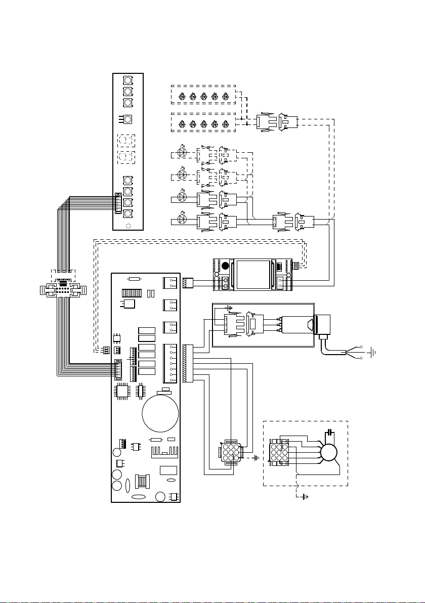
64
Schéma de câblage
0 1 2 3 4 5 6 7 8 9
H90_309
02
Drawing N : Rev :
Modif. by
Doc.status
Do not get quotas from the drawing do not bring
modifications without authorization of techincal office.
According to the law we reserve the own of the present
drawing with reproduction prohibition partial or total.
Approved date
Modification description
Approved by
WIRING DIAGRAM M8-4V ATF LED UL
Doc Type
Denomination
Creation date
18.Apr.2019
DOLCE CORRADO
Created by
991.0454.388
Code
BRWY-G
GRY
123
654
789
123
654
987
RED
WHT
BLU
BLU
BRW
M8-4V
BLU
BLK
ORG
ORG
PNK
7
BRW
MOTOR
6
GRY
5
ORG
4
BLU
3
PNK
F
2
WHT
LINE
120Vac 60Hz
1
BLK
N
FLAT CABLE
LUX2
2
L-B
1
Y-G
BRW
BLK
WHT
GRY
WHT
GRY
BLK
AUX
Faber ATF
2
Y-G
1
LUX1
SEC.
- +
ELECTRONIC
TRNSFORMER
L N
2
ORG(red)
1
ORG(vlt)
FLAT CABLE
GRY (red)
BLK (vlt)
1
2
12
12
GRYGRYGRY
1
LED
BLKBLKBLK
2
1
2
12
GRYGRY
LED
BLKBLK
1
2
12
GRYGRY
LED
BLKBLK
1
2
12
GRYGRY
LED
BLKBLK
BARRA FARETTO LED
12
GRY
BLK
12
BARRA FARETTO LED

65
January 4, 2016
FABER CONSUMER WARRANTY & SERVICE
All Faber products are warranted against any defect in materials or workmanship for the original purchaser
for a period of 1 year from the date of original purchase (requires proof of purchase). This warranty covers
labor and replacement parts. Faber, at its option, may repair or replace the product or components
necessary to restore the product to good working condition. To obtain warranty service, contact the dealer
from whom you purchased the range hood, or the local Faber distributor. If you cannot identify a local Faber
distributor, contact us at (508) 358-5353 for the name of a distributor in your area.
The following is not covered by Faber's warranty:
1. Service calls to correct the installation of your range hood, to instruct you how to use your range hood, to
replace or repair house fuses or to correct house wiring or plumbing.
2. Service calls to repair or replace range hood light bulbs, fuses or filters. Those consumable parts are
excluded from warranty coverage.
3. Repairs when your range hood is used for other than normal, single-family household use.
4. Damage resulting from accident, alteration, misuse, abuse, fire, flood, acts of God, improper installation,
installation not in accordance with electrical or plumbing codes or Faber documentation, or use of products
not approved by Faber.
5. Replacement parts or repair labor costs for units operated outside the United States or Canada, including
any non-UL or C-UL approved Faber range hoods.
6. Repairs to the hood resulting from unauthorized modifications made to the range hood.
7. Expenses for travel and transportation for product service in remote locations and pickup and delivery
charges. Faber range hoods should be serviced in the home.
THIS WARRANTY DOES NOT ALLOW RECOVERY OF INCIDENTAL OR CONSEQUENTIAL DAMAGES, INCLUDING, WITHOUT
LIMITATION, DIRECT, INDIRECT, INCIDENTAL, SPECIAL OR CONSEQUENTIAL DAMAGES, PERSONAL INJURY/WRONGFUL
DEATH OR LOST PROFITS FABER WARRANTY IS LIMITED TO THE ABOVE CONDITIONS AND TO THE WARRANTY PERIOD
SPECIFIED HEREIN AND IS EXCLUSIVE. EXCEPT AS EXPRESSLY SPECIFIED IN THIS AGREEMENT, FABER DISCLAIMS ALL
EXPRESS OR IMPLIED CONDITIONS, REPRESENTATIONS, AND WARRANTIES INCLUDING, WITHOUT LIMITATION, ANY
IMPLIED WARRANTIES OF MERCHANTABILITY OR FITNESS FOR A PARTICULAR PURPOSE
.
This warranty gives you specific legal rights that may vary from state to state.
Model#: ______________________________ Serial #: _____________________________


991.0579.339_03 - 190801
D00005934_02