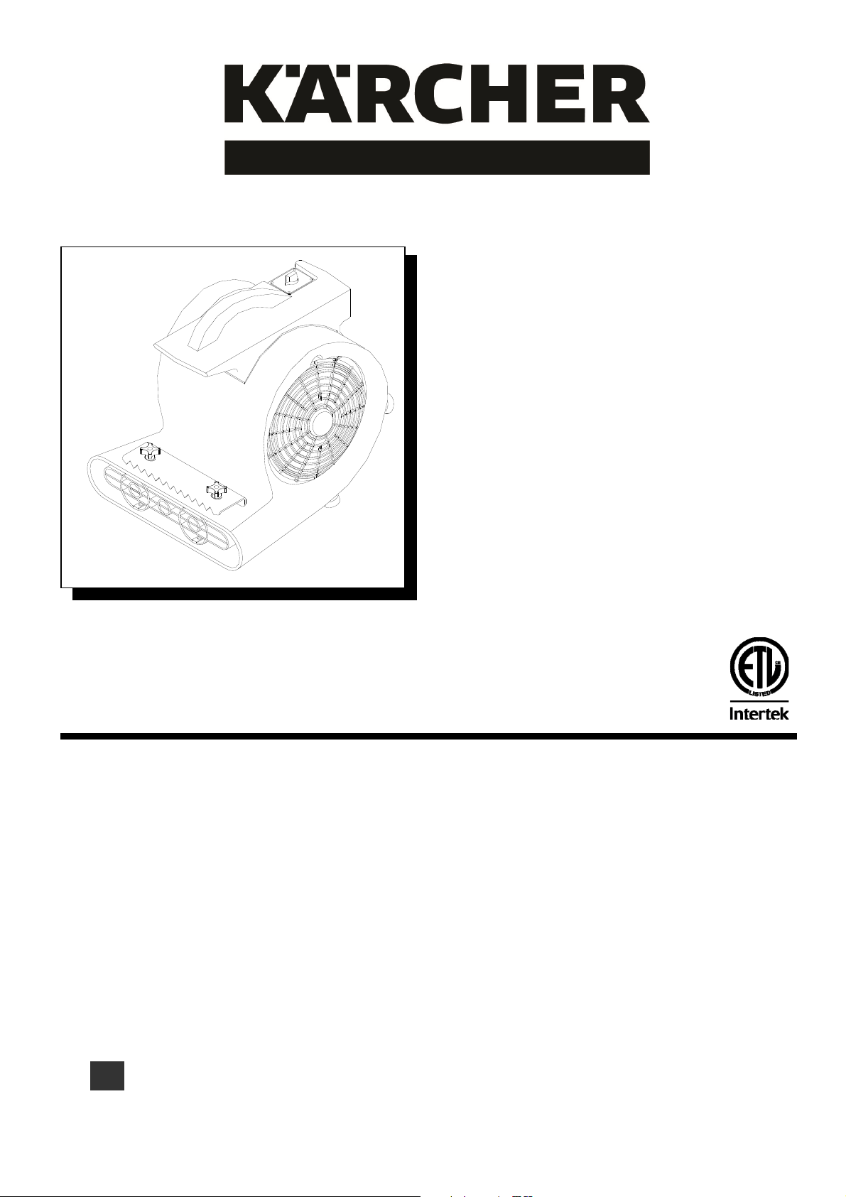
Operating Instructions (ENG)
MODELS:
1.004-052.0
AB84 EU
1.004-053.0
AB84 CUL
1.004-054.0
AB84 JP
1.004-055.0
AB84 GB
1.004-056.0
AB84 CN
Read instructions before operating the machine.
G
86371920
10/31/19
1.004-064.0
AB84 CLASSIC
1.004-065.0
AB84 CLASSIC EU

MACHINE DATA LOG/OVERVIEW
86371920 AB 84 12/14/12
2
For the name and address of your dealer contact: Windsor Industries
YOUR DEALER
Name: __________________________________________________________________________________________________
Address: _______________________________________________________________________________________________
Phone Number: _________________________________________________________________________________________
MODEL _______________________________________
DATE OF PURCHASE __________________________
SERIAL NUMBER ______________________________
SALES REPRESENTATIVE # _____________________
DEALER NAME ________________________________
OPERATIONS GUIDE NUMBER ___________________
PUBLISHED
__________________________________________

HOW TO USE THIS MANUAL
86371920 AB 84 12/14/12
3
This manual contains the following sections:
- HOW TO USE THIS MANUAL
- SAFETY
- OPERATIONS
- MAINTENANCE
- PARTS LIST
The HOW TO USE THIS MANUAL section will tell
you how to find important information for ordering
correct repair parts.
Parts may be ordered from authorized dealers.
When placing an order for parts, the machine
model and machine serial number are important.
Refer to the MACHINE DATA box which is filled
out during the installation of your machine. The
MACHINE DATA box is located on the inside of
the front cover of this manual.
The model and serial number of your machine is
on the back of the machine.
The SAFETY section contains important
information regarding hazard or unsafe practices
of the machine. Levels of hazards is identified that
could result in product or personal injury, or severe
injury resulting in death.
The OPERATIONS section is to familiarize the
operator with the operation and function of the
machine.
The MAINTENANCE section contains preventive
maintenance to keep the machine and its
components in good working condition. They are
listed in this general order:
- Power cord/switch
The PARTS LIST section contains assembled
parts illustrations and corresponding parts list. The
parts lists include a number of columns of
information:
- REF – column refers to the reference
number on the parts illustration.
- PART NO. – column lists the part
number for the part.
- PRV NO. – reference number.
- QTY – column lists the quantity of the
part used in that area of the machine.
- DESCRIPTION – column is a brief
description of the part.
- SERIAL NO. FROM – column
indicates the first machine the part
number is applicable to. When the
machine design has changed, this
column will indicate serial number of
applicable machine. The main
illustration shows the most current
design of the machine. The boxed
illustrations show older designs.
- NOTES – column for information not
noted by the other columns.
NOTE: If a service or option kit is installed on your
machine, be sure to keep the KIT INSTRUCTIONS
which came with the kit. It contains replacement
parts numbers needed for ordering future parts.
NOTE: The number on the lower left corner of the
front cover is the part number for this manual.
MODEL _____________________________________
DATE OF PURCHASE ________________________
SERIAL NUMBER ____________________________
SALES REPRESENTATIVE # ___________________
DEALER NAME ______________________________
OPERATIONS GUIDE NUMBER __________________
PUBLISHED ________________________________

TABLE OF CONTENTS
86371920 AB 84 12/14/12
4
Machine Data Log/Overview. ........................ 2
HOW TO USE THIS MANUAL
How to use this Manual. ............................... 3
Table of Contents ......................................... 4
SAFETY
Important Safety Instructions ........................ 5
Hazard Intensity Level. ................................. 6
Grounding Instructions. ................................. 7
OPERATION
Set Up.. ............................................. ……….8
On/Off Procedure. ............................. ……….8
MAINTENANCE
Power Cord. ............................................... …8
Dust in Motor Windings. ............................. …8
Lubricating Motor Sleeve Bearings. ........... …8
Fan Removal. ............................................ …8
Power Cord/Capacitor.. ............................. …8
Motor Removal. ......................................... …8
Wiring Diagram… ...................................... …9
GROUP PARTS LIST
Body Assembly .......................................... 10
Handle & Wheels ....................................... 12

86371920 AB 84 12/14/12
5
IMPORTANT SAFETY INSTRUCTIONS
When using an electrical appliance, basic precaution
must always be followed, including the following:
READ ALL INSTRUCTIONS BEFORE USING THIS MACHINE.
To reduce the risk of fire, electric shock, or injury:
Use only indoors. Do not use outdoors or expose to rain.
Use only as described in this manual. Use only manufacturer’s recommended components and attachments.
If the machine is not working properly, has been dropped, damaged, left outdoors, or dropped into water,
return it to an authorized service center.
Do not operate the machine with any openings blocked. Keep openings free of debris that may reduce
airflow.
Do not operate this machine near flammable fluids, dust or vapors.
Maintenance and repairs must be done by qualified personnel.
During operation, attention shall be paid to other persons, especially children.
When leaving unattended, secure against unintentional movement.
The machine shall only be operated by instructed and authorized persons.
When leaving unattended, switch off or lock the main power switch to prevent unauthorized use.
Do not handle the plug or machine with wet hands.
Do not unplug machine by pulling on cord. To unplug, grasp the plug, not the cord.
Do not use with damaged cord or plug. Follow all instructions in this manual concerning grounding the
machine.
Do not pull or carry by cord, use cord as a handle, close a door on cord, or pull cord around sharp edges or
corners.
Do not pull/run machine over cord. Keep cord away from heated surfaces.
Connect to a properly grounded outlet. See Grounding Instructions.
Use only on GFCI protected receptacles.
Do not use this fan with any solid-state speed control device.
SAVE THESE INSTRUCTIONS

HAZARD INTENSITY LEVEL
86371920 AB 84 12/14/12
6
The following symbols are used throughout this guide as indicated in their descriptions:
HAZARD INTENSITY LEVEL
There are three levels of hazard intensity identified by signal words -WARNING and CAUTION and FOR
SAFETY. The level of hazard intensity is determined by the following definitions:
WARNING - Hazards or unsafe practices which COULD result in severe personal injury or death.
CAUTION - Hazards or unsafe practices which could result in minor personal injury or product or
property damage.
FOR SAFETY: To Identify actions which must be followed for safe operation of equipment.
Report machine damage or faulty operation immediately. Do not use the machine if it is not in proper
operating condition. Following is information that signals some potentially dangerous conditions to the
operator or the equipment. Read this information carefully. Know when these conditions can exist.
Locate all safety devices on the machine. Please take the necessary steps to train the machine
operating personnel.
FOR SAFETY:
DO NOT OPERATE MACHINE:
Unless Trained and Authorized.
Unless Operation Guide is Read and understood.
In Flammable or Explosive areas.
In areas with possible falling objects.
WHEN SERVICING MACHINE:
Avoid moving parts. Do not wear loose clothing; jackets, shirts, or sleeves when working on the
machine. Use Kärcher approved replacement parts.

GROUNDING INSTRUCTIONS
86371920 AB 84 12/14/12
7
THIS PRODUCT IS FOR COMMERCIAL USE
ONLY.
ELECTRICAL:
The amp, hertz, and voltage are listed on the data
label found on each machine. Using voltages
above or below those indicated on the data label
will cause serious damage to the motors.
EXTENSION CORDS:
If an extension cord is used, the wire size must be
at least one size larger than the power cord on the
machine, and must be limited to 50 feet (15.5m) in
length.
GROUNDING INSTRUCTIONS:
This appliance must be grounded. If it should
malfunction or break down, grounding provides a
path of least resistance for electric current to
reduce the risk of electric shock. This appliance is
equipped with a cord having an equipment-
grounding conductor and grounding plug. The
plug must be inserted into an appropriate outlet
that is properly installed and grounded in
accordance with all local codes and ordinances.
Improper connection of the equipment-
grounding conductor can result in a risk of
electric shock. Check with a qualified
electrician or service person if you are in doubt
as to whether the outlet is properly grounded.
Do not modify the plug provided with the
appliance - if it will not fit the outlet, have a
proper outlet installed by a qualified
electricia
n.

OPERATION & MAINTENANCE
86371920 AB 84 12/14/12
8
OPERATION
1. Open the doors or windows if possible to aid in
ventilation.
2. Ensure that the unit is turned off, plug the
power cord into the outlet.
3. Turn the switch to the desired speed.
4. Turn the unit off before un-plugging the power
cord from the outlet.
MAINTENANCE
1. Frequently inspect power cord for frayed or
damaged insulation.
Remove machine power cord from electrical
source before making any repairs or
adjustments to machine.
POWER CORD/SWITCH
Power cord and switch can be serviced.
1. Remove the 4 screws holding switch down.
2. To replace switch unplug wires and replace
switch. See wiring diagram.
3. To replace power cord see step 1.
4. Unplug wires, loosen strain relief and remove
cord.
5. Replace power cord. See wiring diagram.
CAUTION: When reinstalling motor and fan, make
sure the wires are positioned and secured so they
will not touch fan during rotation.
CAUTION: When reinstalling electrical parts, refer
to wiring diagram for correct connections
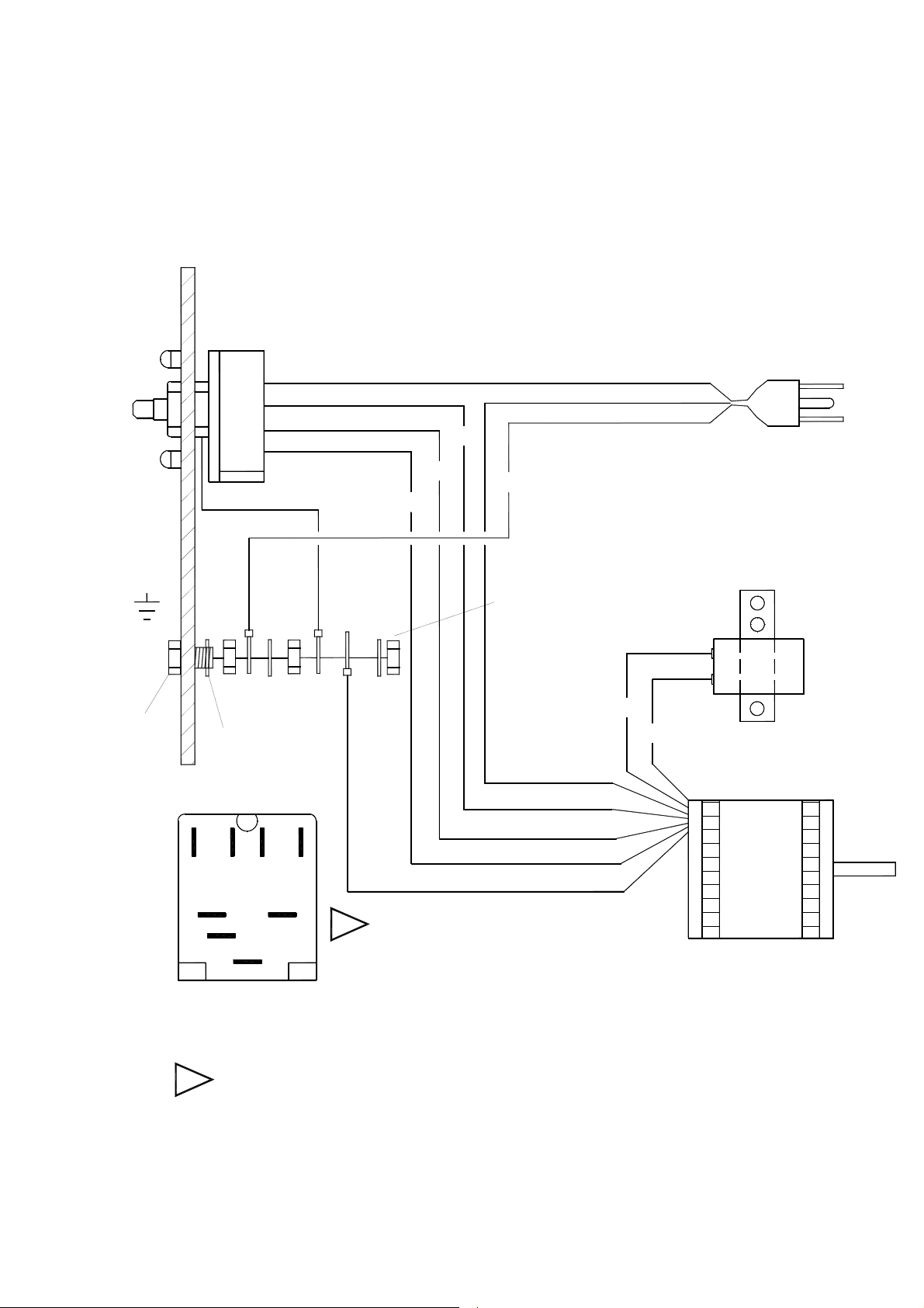
WIRING DIAGRAM
86371920 AB 84 12/14/12
9
L1
3
2
1
CAPACITOR
86247130 115V)
4-POSITION
SWITCH
GRN
BRN
BRN
GRN
RED
BLU
BLK
WHT
GRN
GRN
RED
BLK
BLU
WHT/BLU
POWER
3
12
L1
REAR VIEW OF
SWITCH
BLK/BRN
(86225090)
(86216620)
MOTOR
(86288710)
(86137330)
(86005280 230V)
COVER UNUSED TERMINALS WITH FEMALE COUPLER 86266020.
1
1
(86136310)

AIR BLOWER
86371920 AB 84 09/03/13
10
1
2
3
4
5
6
7
8
10
11
12A
13
14
15
16A
17
20
21
22
23
24
25
26
27
11
29
30
1
1
19
18
19
24
34
31
32B
33
21
26
5
28
9
35
37
38
36
39
28
16B
16D
16C
16E
32A
12B
41

AIR BLOWER PARTS LIST
86371920 AB 84 11/12/13
11
REF PART NO. PRV NO. QTY DESCRIPTION
SERIAL NO.
FROM
NOTES:
1 86136750 70765 8 SCREW, M4-.7 X 15 PNHSM
2 86214700 36210 1 9" BLOWER GRILL
3 86136770 70768 2 SCREW, M6-1 X 16 FLHMS BLKOX
4 86136630 70246 2 SCREW, 8-32 X .25 PHPNHMS BLK
5 86137390 87255 5 WASHER M4 RIVET BACKUP
6 86371710 - 1 KNOB, SWITCH, YLW
7 86136840 70771 1 SET SCR, M3-.5 X 8MM
8 86371730 - 1 PLATE, SWITCH AB, YLW
9 86225090 72176 1 SWITCH AB
10 86288700 140474 1 CLAMP, CAPACITION AB
11 86136540 67481 4 RIVET, M4 X 14MM
12A 86216620 27943 1 CAPACITOR, AB 120VAC ONLY
12B 86375610 - 1 CAPACITOR, RUN, 15uF, 450VAC 230VAC ONLY
13 86223050 62936 1 PLATE, INNER AB
14 86245090 50344 1 LABEL, WARNING
15 86136550 67483 4 RIVET, M3 X 12MM
16A 86217020 - 1 CORD ASSEMBLY, 14X3 SJTX25'AB US & CANADA
16B 86217030 - 1 CORD ASSEMBLY, AUST AB
AUSTRALIA, NEW
ZEALAND & CHINA
16C 86288850 - 1 CORD ASM, AB EURO EUROPE
16D 86364850 - 1 CORD ASM, 230V GB, 25FT GREAT BRITAIN
16E 86371290 - 1 CORD ASM, PSE, AB JAPAN
17 86217840 34389 1 FAN, SQUIRREL CAGE AB
18 86215760 140467 1 BRKT, MOTOR SHAFT AB
19 86136740 70764 2 SCREW, M6-1 X 15 PNHMS BLKOX
20 86214690 36211 1 10" BLOWER GRILL
21 86137340 87211 4 WASHER, M6 FLT BLK
22 86136830 70770 1 SET SCR, M8 X 8MM CUP PT.
23 86217910 66352 4 FOOT, BLOWER
24 86225730 87218 8 WASHER, M6 X 20.5 X 1.6 ZNPLT
25 86136760 70767 4
SCREW, M6-1 X 20 HEXBTNHCS
ISO7380 SS
26 86271550 57220 6 NUT, M6-1 HEX NYLOCK STL ZNPLT
27 86225850 87517 4 WASHER, M3, FL, ISO 7089, SST
28 86225750 87239 4 WASHER M4 INT STAR BLKZNC PLT
29 86218420 36212 1 GUARD, FRONT AB
30 86136730 70763 2 SCREW, M6-1 X 40 PNHMS BLKOX
31 86371720 - 2 KNOB, CARPET CLAMP, YLW
32A 86005280 53556 1 MOTOR 230V 3SPD 1/2HP
32B 86247130 53149 1 MOTOR, 115V 3SPD 1/2HP
33 86216760 20100 1 CLAMP, CARPET AB
34 86198450 20005 1 CLAMP, 5/16 DIA NYLON
35 86079800 62214 1 PLATE, WARNING LABEL
36 86137370 87231 1 WASHER, M18 STAR
37 86136560 87484 1 RIVET, M5 X 20
38 86288680 87230 1 WASHER, M5 RIVET BACKUP
39 86137360 87225 4 WASHER, M4 RIVET BACKUP
40 86372180 - 4 SCREW, M4-.7 X 10 PNHSMS, BLK
41 86245040 50279 1 LABEL, GROUND SYMBOL
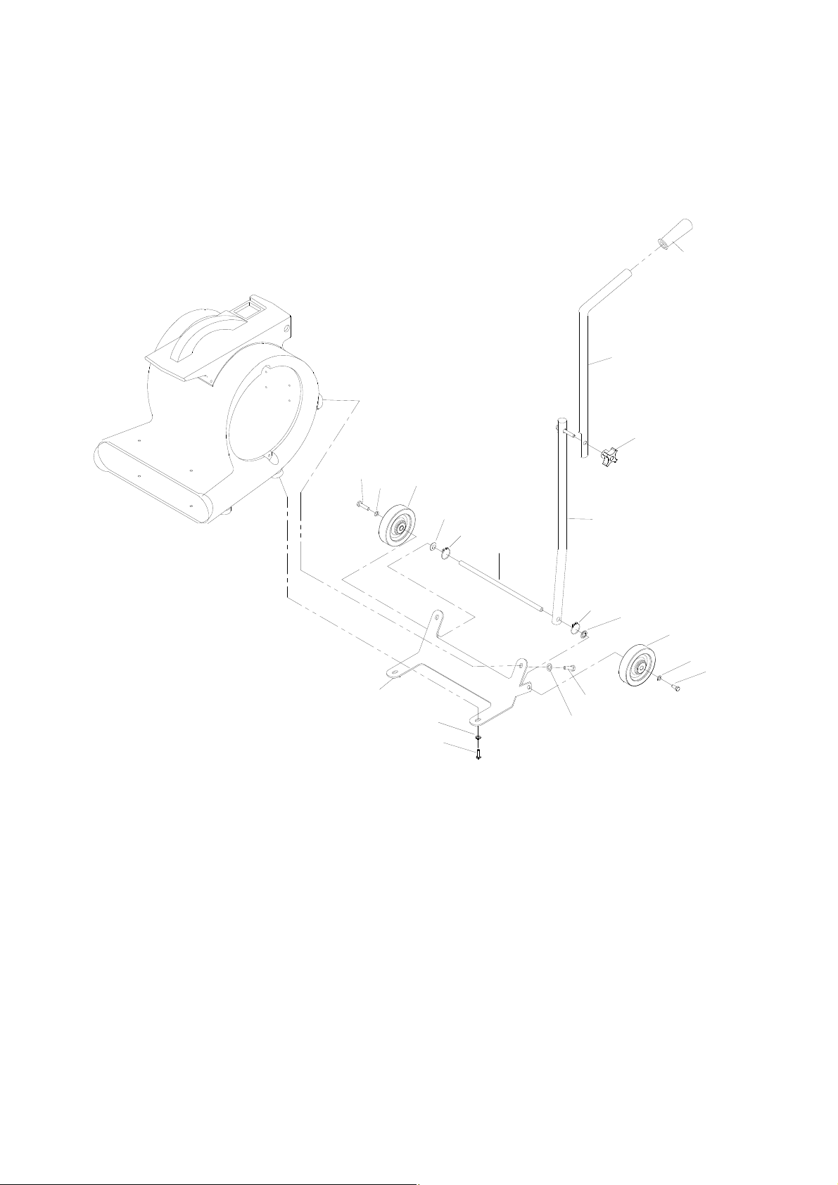
AIR BLOWER HANDLE
86371920 AB 84 12/14/12
12
1
2
3
4
5
6
7
8
9
10
11
12
11
10
13
5
6
7
8
9

AIR BLOWER HANDLE
86371920 AB 84 12/14/12
13
REF
PART
NO.
PRV
NO.
QTY DESCRIPTION
SERIAL
NO.
NOTES:
1 86004070 36196 1 GRIP, POLISHER HANDLE
2 86292520 - 1 TUBE, HANDLE UPR, LONG
3 86371700 - 1 KNOB, HANDLE LOCK, YLW
4 86225400 78485 1 TUBE, HANDLE LOWER
5 86223500 67469 2 RING, 13MM EXTERNAL SNAP
6 86222270 57276 2 NUT, .51 PUSH SPRST
7 86226020 89206 2 WHEEL 5D X 1.25 X 13MMID GRY
8 86137280 87054 2 WASHER, M8 FLAT DIN125A PLT
9 86136640 70262 2 SCR, M8-1.25 X 20 HHMS PLT
10 86136760 70767 2
SCREW, M6-1 X 20 HEXBTNHCS
ISO7380 SS
11 86137380 87233 2 WASHER, 20MM OD
12 86215490 140495 1 BRACKET, WHEEL AB
13 86214960 03118 1 AXLE, BLOWER WHEEL