Owner’s Manual
Thermoplastic
Jet Pumps
General Safety . . . . . . . . . . . . . . . . . . . . 2
Installation . . . . . . . . . . . . . . . . . . . . . 3-8
Pipe and Tank Connections . . . . . . . . . . 9
Electrical . . . . . . . . . . . . . . . . . . . . . . . .10
Operation . . . . . . . . . . . . . . . . . . . . . . . 11
Troubleshooting . . . . . . . . . . . . . . . . . . 12
Parts . . . . . . . . . . . . . . . . . . . . . . . . . . . 13
Ejector Kit . . . . . . . . . . . . . . . . . . . . . . . 14
Warranty . . . . . . . . . . . . . . . . . . . . . . . . 15
TABLE OF CONTENTS
Plastic Well Ejector Kit
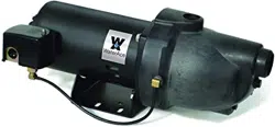
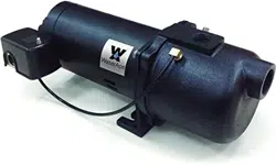
Shallow Well Jet
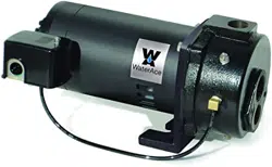
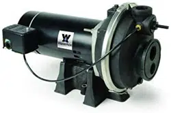
Convertible Well Jet
2
Fill Pump with water to prime: Ensure pump body is lled with water to discharge.
Motor’s Electrical Settings: Set motor to proper voltage.
Help Line: Call 1-844-394-2604 for assistance
STOP
Before you start
GENERAL SAFETY
SAFETY LABELS
Important Safety Instructions Carefully read and follow all safety instructions in this manual and on pump.
SAVE THESE INSTRUCTIONS – This manual contains important instructions that should be followed during installation,
operation, and maintenance of the product. Save this manual for future reference.
This is the safety alert symbol. When you see this symbol on your pump or in this manual, look for one of the
following signal words and be alert to the potential for personal injury!
Indicates a hazard which, if not avoided,
will result in death or serious injury.
Indicates a hazard which,if not avoided,
could result in death or serious injury.
Indicates a hazard which,if not avoided,
could result in minor or moderate injury.
NOTICE
indicates practices not related to personal injury.
Keep safety labels in good condition. Replace missing or
damaged safety labels.
• Keep pump equipment out of the reach of children! Failure
to follow the directions given could cause serious risk to
individuals or objects.
• DO NOT work on pump until power is disconnected.
• DO NOT cut o ground pin or use an adapter tting.
• DO NOT use an extension cord.
• The pump power cord should be connected to a sepa-
rately fused, grounded line with a minimum capacity of
15 amps. It can be connected to a non-fused breaker at
the recommended amperes.
• ELECTRICAL PRECAUTIONS - Before servicing the
pump, always shut o the main power breaker and then
unplug the pump. Make sure you are not standing in
water and are wearing insulted protective shoes under
ood conditions. Contact your local electric company or
a qualied licensed electrician for dicconnecting electrical
service prior to pump removal.
• Follow all local electrical and safety codes, as well as
the National Electrical Code (NEC) and the Occupational
Safety and Health Act (OSHA)
• Replace damaged or worn wiring cord immediately.
• Do not kink power cable and never allow the cable to
come in contact with oil, grease, hot surfaces, or
chemicals.
• Wire motor to correct supply. See motor nameplate and
wiring diagrams and check voltage of power supply.
• Unit must be securely and adequately electrically ground-
ed. This can be accomplished by wiring the unit to a
ground metal-clad raceway system or by using a separate
ground wire connected to the bare metal of the motor
frame or other suitable means.
• Do not disassemble the motor housing. This pump has
no repairable internal parts and disassembling may cause
leakage or dangerous electrical wiring issues.
• Make certain the electrical power source is adequate for
the requirements of the pump.
• Install pressure relief valve in the discharge pipe. Release
all pressure on system before working on any component.
• The following may cause severe damage to pump and will
void the warranty.
- Using an extension cord.
- Cutting o the ground pin or using an adapter tting.
- Working on the pump or switch while plugged in.
- Removing motor housing, unscrewing impeller or other
wise removing impeller seal
- Running the pump continuously.
- Pumping chemicals or corrosive liquids.
- Pumping gasoline or other ammable liquids.
• This pump is only to be used for water systems.
• Protect the power cable from coming in contact with
sharp objects.
• Do not run pump dry.
• Pump and plumbing must be full of water before startup.
• Do not pump water which contains sand, mud, silt or
debris.
• Be careful when touching the exterior of a motor. It may
be hot enough to be painful or cause injury.
• Do not allow pump or any system component to freeze.
To do so will void the warranty.
continued
WA5PJSW
WA7PJSW
WA10PJSW
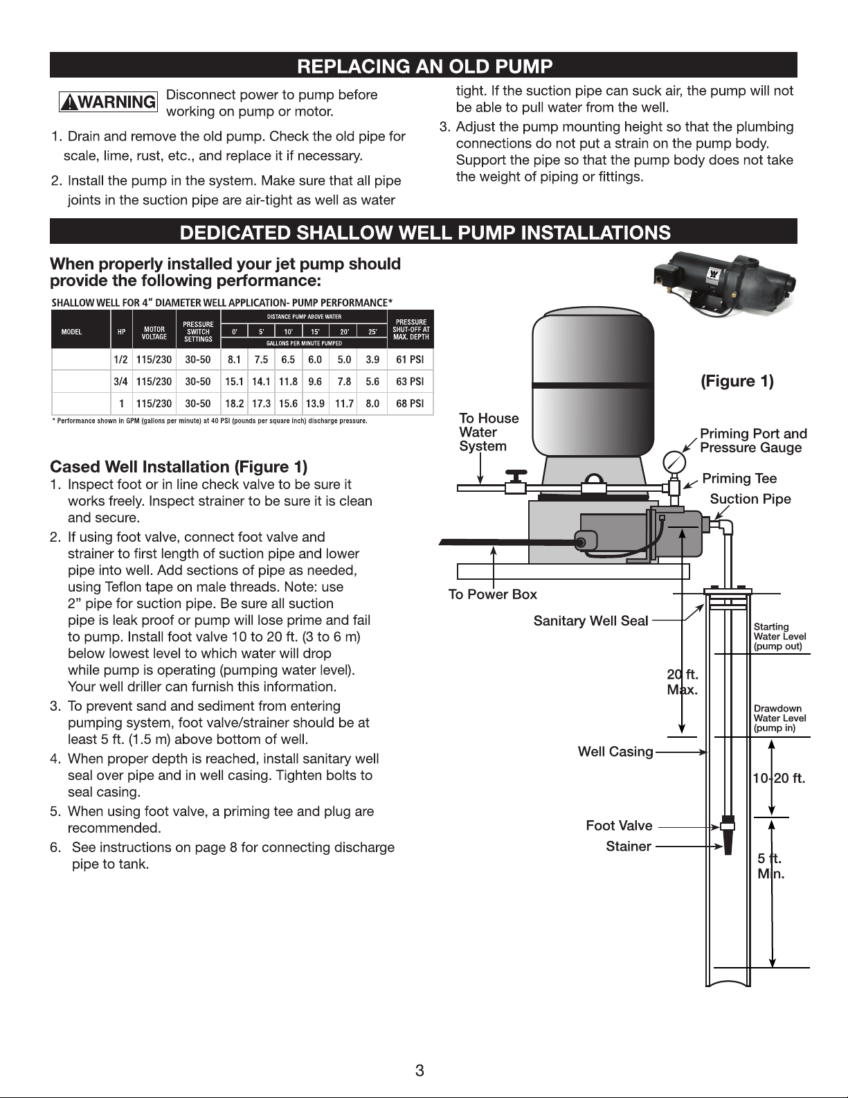
SHALLOW WELL PUMP INSTALLATIONS
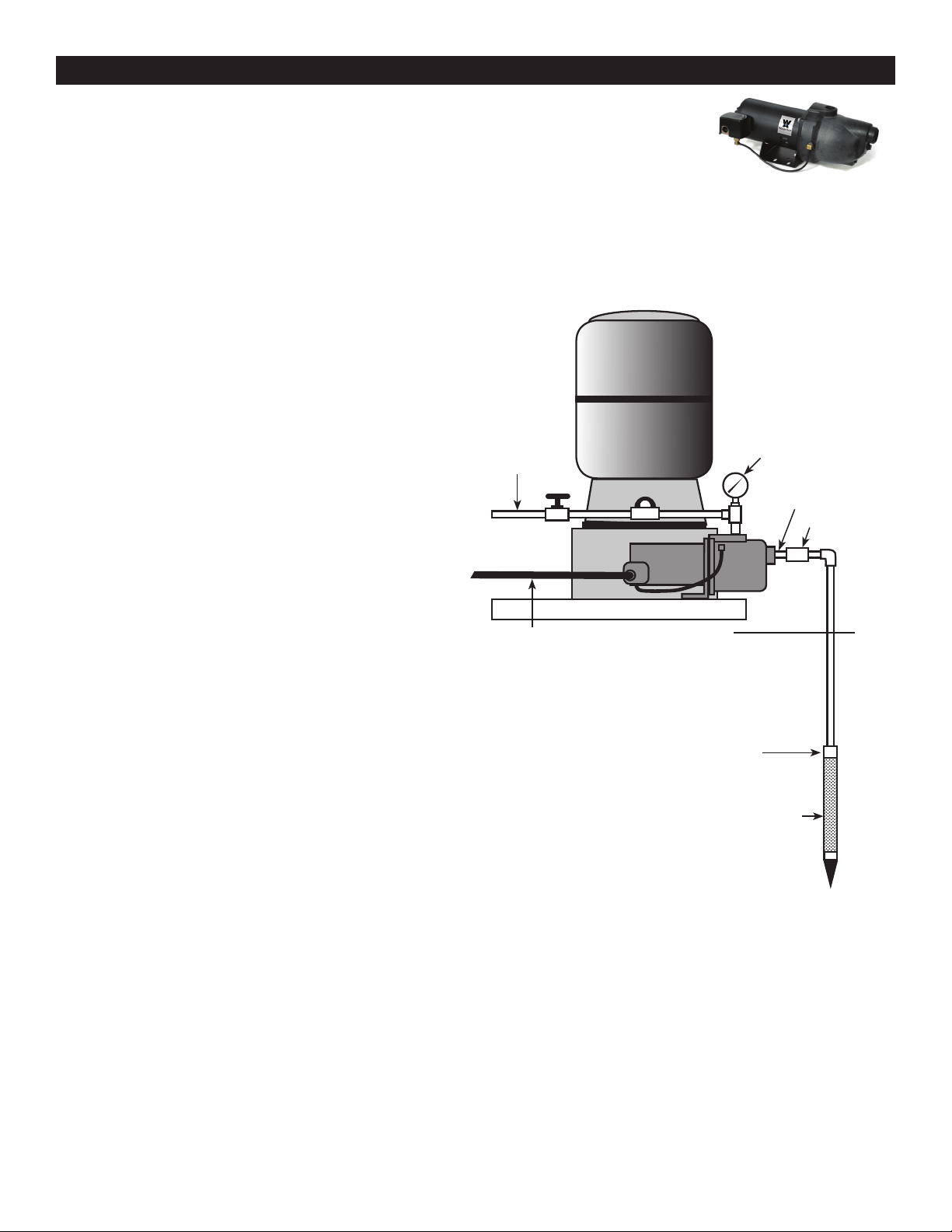
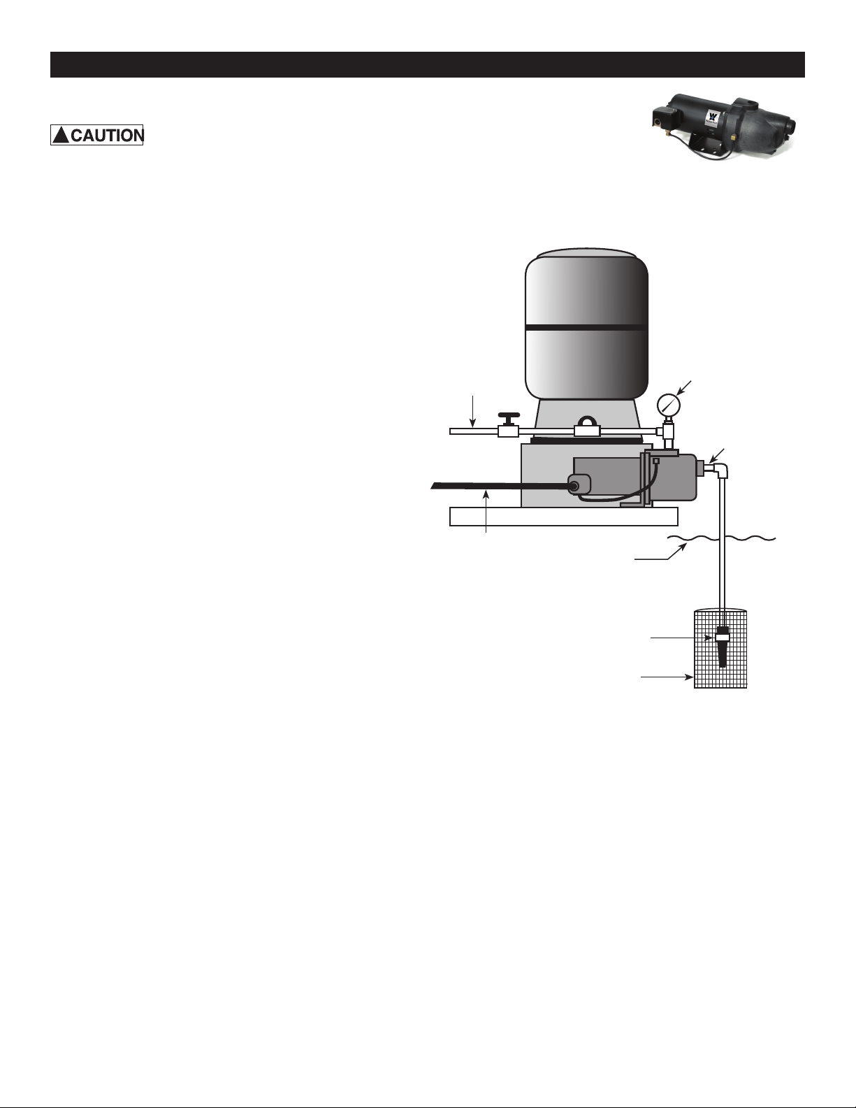
Driven Point Installation (Figure 2)
1. Drive the well point, using “drive couplings” and a “drivecap”.
“Drive ttings” are threaded all the way through and allow the
pipe ends to butt against each other so that the driving
force of the maul is carried by the pipe and not by the threads.
The ordinary ttings found in hardware stores are not threaded
all the way through the tting and can collapse under impact.
“Drive ttings” are also smoother than standard plumbing
ttings, making ground penetration easier.
2. Mount the pump as close to the well as possible.
3. Use the fewest possible ttings (especially elbows) when
connecting the pipe from the well point to the pump suction
port. The suction pipe should be at least as large as the suction
port on the pump.
4. Install a check as shown.
5. Install a priming tee, priming plug, and pressure gauge
to pump’s discharge port. Connect the pipe from the
well to the pump’s suction port, using the fewest
possible ttings-especially elbows. Fittings increase
friction in the pipe. The suction pipe should be at least
as large as the suction port on the pump. Support
the pipe so that there are no dips or sags in the pipe,
so not to strain the pump body, and so that it
slopes slightly upward from the well to the pump
(Note: Not doing so can create air locks preventing
the pump from working properly). Seal the suction
pipe joints with PTFE pipe thread sealant tape or a
PTFE based pipe joint compound. Joints must be air
and water tight. If the suction pipe can suck air,
the pump cannot pull water from well.
6. If one well point does not supply enough water,
consider connecting two or three well points to one
suction pipe.
7. See instructions on page 8 for connecting discharge
pipe to tank.
(Figure 2)
Drive Point
Drive
Coupling
Check Valve
To Power Box
Suction Pipe
Priming Tee with
Priming Port,
Plug and Pressure
Gauge
To House
Water
System
4
SHALLOW WELL PUMP INSTALLATIONS
Surface Water Installation (Figure 3)
Possible contamination. Do not use
surface water for drinking. The installation
shown could be used for sprinkler applications.
1. The pump should be installed as close to the water
as possible, with the fewest possible ttings (especially
elbows) in the suction pipe. The suction pipe should
be at least as large as the suction port on the pump.
2. Assemble a foot valve and strainer to the suction pipe.
Make sure that the foot valve works freely. Use PTFE
pipe thread sealant tape or a PTFE-based pipe joint
compound on threaded pipe joints.
3. Install a screen to protect the water system from letting
debris enter the system.
4. Lower the pipe into the water until the strainer is ve
feet above the bottom. It should also be at least 10”
below the water level in order to prevent the pump
from sucking air. Strainer and pipe should be supported.
5. Install a priming tee, priming plug, and pressure gauge
to pump’s discharge port. Connect the pipe from the
well to the pump’s suction port, using the fewest
possible ttings. Fittings increase friction in the pipe.
The suction pipe should be at least as large as the
suction port on the pump. Support the pipe so that there
are no dips or sags in the pipe, so not to strain the pump
body, and so that it slopes slightly upward from the
water to the pump (Note: Not doing so can create air
locks preventing the pump from working properly). Seal
the suction pipe joints with PTFE pipe thread sealant
tape or a PTFE based pipe joint compound. Joints must
be air and water tight. If the suction pipe can suck air,
the pump can not pull water from well.
6. Joints must be air and water-tight. If the suction pipe
can suck air, the pump cannot pull water from the
water source.
7. See instructions on page 8 for connecting discharge
pipe to tank.
!
(Figure 3)
Foot Valve
Screen
Water Surface
To Power Box
Suction Pipe
Priming Tee with
Priming Port, Plug
and Pressure
Gauge
To End
Use
5
REPLACING AN OLD PUMP
CONVERTIBLE WELL INSTALLATION
For parts or assistance, call ECO-FLO Customer Service at 1-877 326-3561
Disconnect power to pump before
working on pump or motor.
1. Drain and remove the old pump. Check the old pipe for
scale, lime, rust, etc., and replace it if necessary.
2. Install the pump in the system. Make sure that all pipe
joints in the suction pipe are air-tight as well as water
tight. If the suction pipe can suck air, the pump will not
be able to pull water from the well.
3. Adjust the pump mounting height so that the plumbing
connections do not put a strain on the pump body, and
ensure the pump’s height is above the water source.
Support the pipe so that the pump body does not take
the weight of piping or ttings.
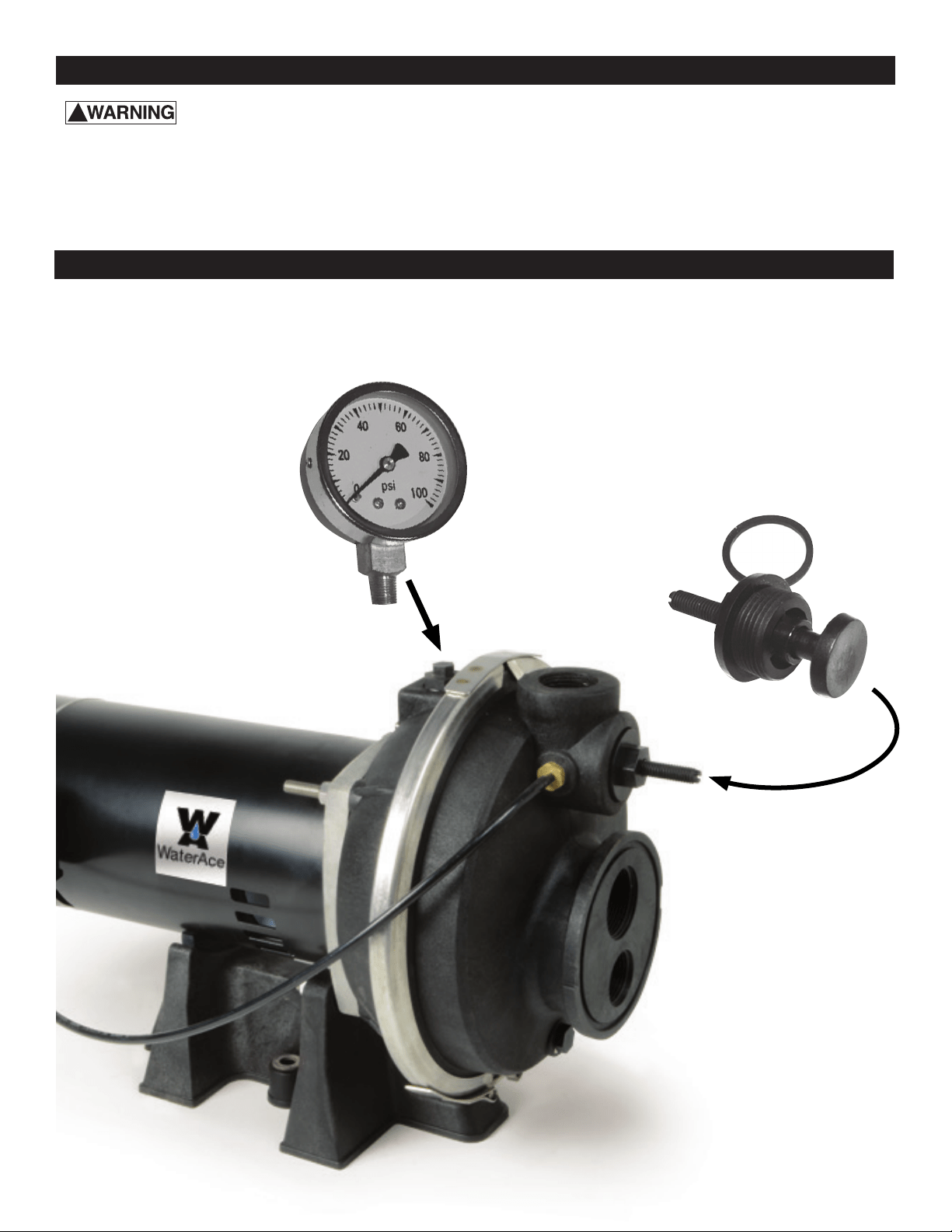
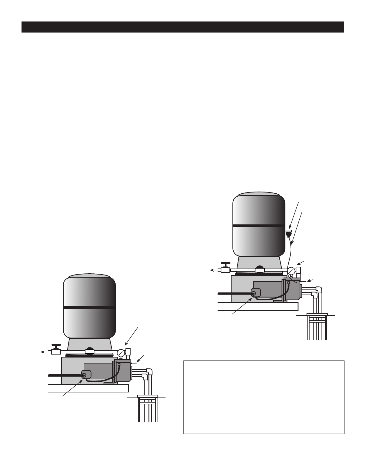
1. Install the pressure gauge in the primary port as shown
in Figure 1 by removing plug and securely screwing
pressure gauge in place. Use PTFE tape on gauge
threads.
2. Install the pressure regulator control valve as shown in
Figure 2. Be sure to use the provided gasket and secure
rmly.
!
3
Convertible
Jet Pump
(Figure 1)
(Figure 2)
6
7
Convertible
Jet Pump
CONVERTIBLE WELL PUMP INSTALLATIONS
A Convertible Jet Pump can be used either in shallow well applications, (0-25’) or in deep well
applications, (26’ to 70’). Both measurements are from the intake port of the pump to the water
source. The pump can be converted shallow to deep or deep to shallow.
When properly installed your jet pump should provide the following performance:
* Performance shown in GPM (gallons per minute) at 40 PSI (pounds per square inch) discharge pressure.
WA5PJCW 1/2 115/230 30-50 5.9 4.7 3.6 2.9 2.4 1.6 - - - - 63 PSI
WA7PJCW 3/4 115/230 30-50 8.0 6.2 5.9 4.2 3.1 2.5 1.7 1.5 1.1 - 63 PSI
WA10PJCW 1 115/230 30-50 11.1 8.7 7.2 6.2 5.1 4.6 3.0 2.2 1.6 1.1 65 PSI
GALLONS PER MINUTE PUMPED
MODEL HP 20’ 30’ 40’ 50’ 60’ 70’ 80’ 90’ 100’ 110’
MOTOR
VOLTAGE
PRESSURE
SWITCH
SETTINGS
PRESSURE
SHUT-OFF AT
MAX. DEPTH
DEEP WELL FOR 4” DIAMETER WELL APPLICATION- PUMP PERFORMANCE*
DISTANCE PUMP ABOVE WATER
* Performance shown in GPM (gallons per minute) at 40 PSI (pounds per square inch) discharge pressure.
MODEL HP 5’ 10’ 15’ 20’ 25’
WA5PJCW 1/2 115/230 30-50 5.5 4.7 4.0 3.5 3.1 63 PSI
WA7PJCW 3/4 115/230 30-50 15.3 13.1 9.3 6.0 5.5 63 PSI
WA10PJCW 1 115/230 30-50 16.8 15.7 13.5 7.2 6.5 65 PSI
MOTOR
VOLTAGE
PRESSURE
SWITCH
SETTINGS
PRESSURE
SHUT-OFF AT
MAX. DEPTH
DISTANCE PUMP ABOVE WATER
SHALLOW WELL FOR 4” DIAMETER WELL APPLICATION- PUMP PERFORMANCE*
GALLONS PER MINUTE PUMPED
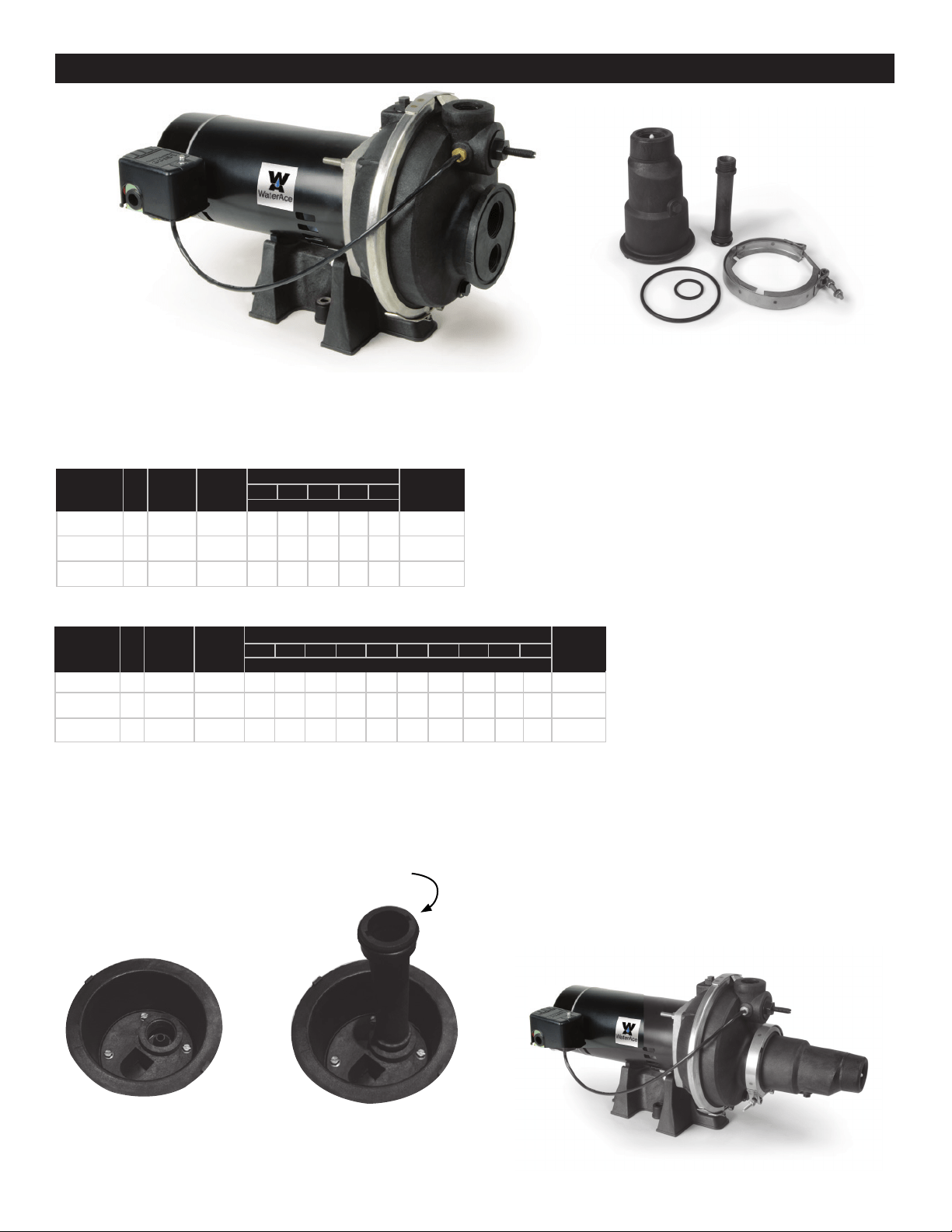
1. Note the nozzle is used in both shallow well and deep
well applications and is installed in the ejector at the
factory (Fig. A).
2. Install the shallow well venturi tube in the ejector
housing (Fig.B). Place o-ring lubricant on o-ring.
Preparing the Convertible Jet Pump for Shallow Well Application
(Fig. A) (Fig. B)
(Fig. C)
4. Mount the ejector on to the convertible well pump
placing the o-ring between the ejector and in the
groove of the jet pump’s body. Add o-ring lubricant to
o-ring to help hold in place. See (Fig. C) below.
5. Secure the ejector to the pump body by tightening the
ring clamp with a wrench.
6. Ensure the ring clamp is tight.
7. You have now completed assembling the convertible
jet pump for shallow well applications and are ready to
install your pump.
3. Hand tighten the venturi tube into the ejector.
Ejector
Ejector
Gaskets
Ring Clamp
Venturi Tube
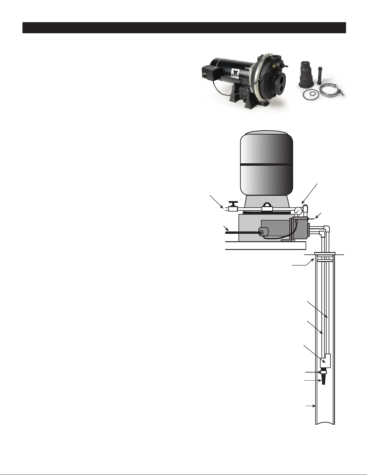
Preparing the Convertible Jet Pump for Deep Well Application,
i.e. 26-70’, 4” diameter wells. (Figure 4)
CONVERTIBLE WELL PUMP INSTALLATIONS
1. Install the pressure regulator control valve along
with pressure gauge (g 2).
2. Prepare the ejector.
3. Note the nozzle is installed at the factory in the
ejector body (see g A, page 6).
4. Select and install the venturi tube marked with a
DW. DW denotes deep well. Install as described
above. (see g.B, page 6)
5. Install a short pipe and foot valve to the intake
end of the ejector to ensure the pipes do not lose
water and remain primed when the jet pump’s
motor is o.
6. Using the proper pipe for each port in the ejector,
install pipe on the ejector (Figure 4) and
begin lowering it into the water source to the
depth you have determined will optimize your
pump’s water performance.
7. Note the pipes will be two dierent sizes to
optimize the jet pump’s performance. One pipe
will be 1” and the other will be 1-1/4” in diameter.
8. Attach the opposite ends of the pipes to the intake
ports of the jet pump (see Figure 4).
9. Install a sanitary well seal and connect the
ejector piping to the pump. Use steel nipples
through the well seal with exible poly pipe to
avoid crushing the plastic pipe when tightening
the seal.
10. Support the pipe so that there are no dips or sags
in the pipe, so it doesn’t strain the pump body,
and so that it slopes slightly upward from the well
to the pump (high spots can cause air pockets
which can air lock the pump). Seal the suction
pipe joints with PTFE pipe thread sealant tape or
a PTFE-based pipe joint compound. Joints must
be air and water-tight. If the suction pipe can suck
air, the pump cannot pull water from the well.
11. You are now ready to prime the pump per
instructions on page 10.
12. See instructions on page 8 for connecting
discharge pipe to tank.
(Figure 4)
Priming tee with
priming port, plugs,
pressure gauge and
pressure regulator
control
Foot Valve
Ejector
Drive Line
to Well
Suction Pipe
from Well
Stainer
Well Casing
Sanitary
Well Seal
To Power Box
To House
Water
System
Priming Tee
with Priming
Port, Plug and
Pressure Gauge
8
Deep Well
Ejector Kit
Pressure
Regulator
Control Valve
DISCHARGE PIPE AND PRESSURE TANK CONNECTIONS
Connecting Pump Discharge to Pre-Charged
Tank Connections (Figure 5)
1. Install two tees in the pump discharge port. The pipe
size must be at least as large as the discharge port.
2. Run a pipe from one arm of the tee in the pump’s
discharge port to the end of the tee installed in the
pre-charged tank.
3. Connect the other end of the tank tee to your
plumbing system.
4. Cap the remaining openings in the tees with a
threaded plugs or a pressure gauge.
5. Check the air pressure in the tank using an ordinary tire
gauge.
6. The air pressure should be 2 PSI less than the cut in
setting of the pump’s pressure switch.
7. The pre-charge tank’s pressure is measured when
there is no water in the tank.
8. For example, if your pump has a 30/50 PSI pressure
switch, your pump will turn on when the pressure in
the line drops to 30 PSI (cut in pressure) and will turn
o when the pressure in the line increases to 50 PSI
(cut out pressure). The air pressure in the tank should
be set at 28 PSI, (30-2)
9. Fill pump body with water.
10. Go to Electrical section.
Connecting Pump Discharge to Standard Tank
(Figure 6)
1. Install two tees in the pump discharge port.
2. Run a pipe from one arm of the tee installed in the
pump’s discharge port to the end of the tee installed in
the tank.
3. Connect the other end of the tank tee to your plumbing
4. Install in another opening of the pump tees a reducer
bushing down to 1/8” NPT in the tee.
Run tubing from the tee to the port on the Air Volume
Control (AVC) mounted on the tank.
5. Cap the remaining openings with a threaded plug or
pressure gauge.
6. Seal all joints with PTFE pipe thread sealant tape
or a PTFE-based pipe joint compound. See instructions
provided with the tank and the AVC for details.
7. Pour water in the pump.
8. Go to Electrical section.
Sealing Pipe Joints
Use only PTFE pipe thread sealant tape or PTFE-based
joint compounds for making all threaded connections
to the pump itself. Do not use pipe joint compounds on
plastic pumps: they can react with the plastic in pump
components. Make sure that all pipe joints in the
suction pipe are air tight as well as water tight. If the
suction pipe can suck air, the pump will not be able to
pull water from the well.
Pressure
Regulator
Control Valve
To House
Water System
Pressure
Switch
(Figure 6) Standard Tank Connections
(Figure 5) Precharged Tank Connections
Priming tee with priming port, plugs, pressure
gauge and pressure regulator control
9
Priming Tee
with Priming
Port, Plug and
Pressure Gauge
Priming Tee
with Priming
Port, Plug and
Pressure Gauge
To House
Water System
Pressure
Switch
Air Volume
Control Tube
Air Volume Control
Pressure
Regulator
Control Valve
10
ELECTRICAL
BRANCH
AWG
DISTANCE IN FEET FROM MOTOR TO SUPPLY
MAX. LOAD
FUSE
MIN. WIRE
0-100 101-200 201-300 301-400 401-500
MOTOR HP VOLTS AMP RATING AMP SIZE (mm
2
) AWG WIRE SIZE (mm
2
)
1/2 115/230 12.2/6.1 15/15 12/14 (3/2) 12/14 (8.4/2) 8/14 (2/2) 6/14 (14/2) 6/12 (14/3) 4/10 (21/5.5)
3/4 115/230 11.5/5.8 20/15 10/14 (5.5/2) 12/14 (8.4/2) 8/14 (8.4/2) 6/12 (14/3) 4/10 (21/5.5) 4/10 (21/5.5)
1 115/230 11.9/6.0 25/15 10/14 (5.5/2) 6/14 (14/2) 8/14 (8.4/2) 6/12 (14/3) 4/10 (21/5.5) 4/10 (21/5.5)
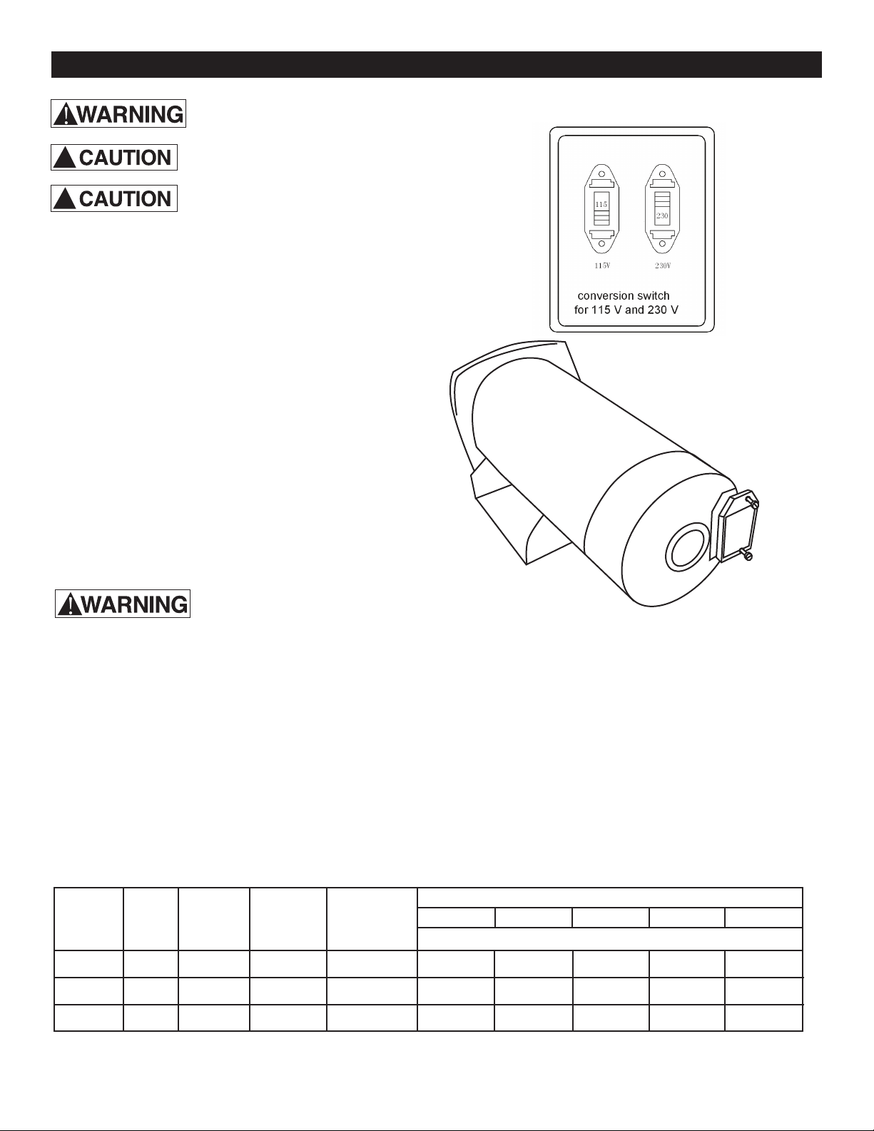
Motor Switch Settings (Figure 8)
Motors are designed to run on either 115 volt or 230 volt
current. Be sure switch is set properly for the incoming
voltage. SETTING SWITCH FOR INCORRECT VOLTAGE
WILL DAMAGE MOTOR AND VOID WARRANTY! IF YOU
DO NOT KNOW THE SUPPLY VOLTAGE CONTACT LI-
CENSED ELECTRICIAN.
Wiring Pressure Switch
Attach the wires from the power source to the pressure
switch following the directions provided under the cover
of the pressure switch. Remove the pressure switch cover
and follow wiring directions under the cover lid. Be sure to
ground wire is properly connected (Figure 9).
Disconnect power before working on
pump, motor, pressure switch or wiring
Motor may be hot. Allow to cool 20
minutes.
Water pressure may have built up in
the pump, pipes and/or tank. Drain
water to relieve pressure.
!
!
Wiring
Risk of electric shock.
Can shock, burn or kill.
1. To avoid dangerous or fatal electrical shock, turn OFF
power to circuit before working on electrical
connections.
2. Ground motor before connecting to electrical power
supply. Failure to ground motor can cause severe or
fatal electrical shock hazard.
3. Supply voltage must be within +/- 10% of nameplate
voltage. Incorrect voltage can cause re or damage
motor and voids warranty. If in doubt consult a
licensed electrician.
4. Use wire size specied in Wiring Chart (below). If
possible, connect pump to a separate branch circuit
with no other appliances on it.
5. Do not ground to a gas supply line.
6. Wire motor according to diagram on motor nameplate.
If nameplate diagram diers from diagrams above,
follow nameplate diagram.
7. If this procedure or the wiring diagrams are
confusing, consult a licensed electrician.
8. Pump must be on dedicated circuit with no other
equipment on circuit.
Wiring Chart Recommended Wire and Fuse Sizes for 115 and 230 volts
(Figure 9) Remove
Motor End Cover
to Access Voltage
Switch (some
models only)
Figure 8

11
Hazardous Pressure,
Install pressure relief valve in discharge pipe.
Release all pressure on system before working on any component.
OPERATION
You may have to repeat this two or three times in order
to get all the trapped air out of the piping.
6. As pump begins to build pressure, close faucet. When
water pressure has built up and is maintained
by the pump, slowly close the pressure regulator control
valve while watching the pressure gauge needle.
Continue closing the valve until you see the pressure
gauge needle start to utter. If the needle starts to
utter, slowly open the valve just enough to stop the
utter. Your pump is now operating at peak eciency.
7. Close all open faucets. After the pump has built up
pressure in the system and shut o, check the
pressure switch operation by opening a faucet or two
and running enough water out to bleed o pressure
until the pump starts. If your jet has a 30/50 pressure
switch, the pump should start when the pressure
drops to 30 PSI and stop when pressure reaches 50
PSI. Run the pump through one or two complete cycles
to verify correct operation. This will also help clean the
system of dirt and scale dislodged during installation.
Winterizing
1. Turn o power and open faucets to relieve system
pressure.
2. Drain pump of all winter and leave drain plug out
until restarting pump.
Risk of burns. Never run pump dry. Running
pump without water may cause pump to overheat, damag-
ing seal and possibly causing burns to persons handling
pump. Fill pump with water before starting.
Be sure the pump is full of water before
starting the motor.
Risk of explosion and scalding. Never run
pump against closed discharge. To do so can boil water
inside pump, causing hazardous pressure in unit, risk of
explosion and possible scalding persons handling pump.
1. Open the faucet and pressure regulator control valve
as far as possible. Remove the priming plug from the
pump and ll the pump, ll all piping between the pump
and the well, and make sure that all piping in the well is
full. If you have also installed a priming tee in the suction
piping, remove the plug from the tee and ll the suction
piping.
2. Replace all ll plugs. Leave the pressure regulator control
valve open (in a shallow well installation, the pressure
regulator control valve always stays open).
3. Turn electric power on.
4. Start the pump. The pump should pump water in two
or three minutes.
5. If you don’t have water after 2 to 3 minutes, stop the
pump and remove the ll plugs. Rell the pump and
piping. You may have to repeat this two or three times
in order to get all the trapped air out of the piping. The
control valve remains open throughout this procedure.
6. As pump begins to build pressure, close faucet. Pump
should continue to build pressure until pressure switch
shuts o. Check the pressure switch operation by
opening a faucet or two and running enough water out
to bleed o pressure until the pump starts. If your jet
has a 30/50 pressure switch, the pump should start
when the pressure drops to 30 PSI and stop when
pressure reaches 50 PSI. Run the pump through one or
two complete cycles to verify correct operation. This will
also help clean the system of dirt and scale dislodged
during installation.
PREPARING TO START THE PUMP - SHALLOW WELL
PREPARING TO START THE PUMP - DEEP WELL CONVERTIBLE
Risk of burns. Never run pump dry.
Running pump without water may cause pump to overheat,
damaging seal and possibly causing burns to persons
handling pump. Fill pump with water before starting.
Be sure the pump is full of water before
starting the motor.
Risk of explosion and scalding. Never
run pump against closed discharge. To do so can boil water
inside pump, causing hazardous pressure in unit, risk of
explosion and possibly scalding persons handling pump.
1. Open the pressure regulator control valve as far as
possible. Then remove the priming plug from the pump
and ll the pump, ll all piping between the pump and the
well, and make sure that all piping in the well is full.
If you have also installed a priming tee in the suction
piping, remove the plug from the tee and ll the suction
piping.
2. Replace all plugs.
3. Turn electric power on.
4. Start the pump and watch the pressure gauge. The
pressure should build rapidly to 50 PSI as the pump
primes.
5. Open several faucets in the residence to permit water
ow and to release trapped air. After 2 or 3 minutes, the
gauge should show pressure. If not, stop the pump,
remove the ll plugs, and rell the pump and piping.
!
!
!
!
!
!

CORRECTIVE ACTION
Replace fuse or reset circuit breaker.
DISCONNECT POWER; Replace starting switch
Refer to instructions on wiring (Page 9). DISCONNECT POWER; check and
tighten all wiring. Hazardous voltage. Capacitor voltage may be
hazardous. To discharge capacitor, hold insulated handle screwdriver BY THE
HANDLE and short capacitor terminals together. Do not touch metal screwdriver
blade or capacitor terminals. If in doubt, consult a qualified electrician.
Refer to instructions on conversion switch.
Check with power company. Install heavier wiring if wire size is too small (See
Electrical/Wiring Chart)
See section below on too frequent cycling.
In new installation:
1. Re-prime according to instructions.
2. Check all connections on suction line and AVC with shaving cream.
3. Replace foot valve or check valve.
In installation already in use:
1. Check all connections on suction line and shaft seal.
2. Lower suction line into water and re-prime. If receding water level in
well exceeds 25’ (7.6M0, a deep well pump is needed.
3. Replace faulty valve.
Clean foot valve or strainer
Clean ejector or impeller.
Replace check valve or foot valve.
Thaw pipes. Bury pipes below frost line. Heat pit or pump house.
Raise foot valve and/or strainer above bottom of water source. Clean foot valve
and strainer.
A deep well jet will be needed if your well is more than 25’ (7.6M0 depth to
water.
A new nozzle and venturi combination may be needed.
Replace with plastic pipe where possible, otherwise with new steel pipe.
Use larger piping.
DISCONNECT POWER; adjust or replace pressure switch
Close faucets
Clean venturi, nozzle or impeller
Drain tank to air volume control port. Check AVC for defects. Check all
connections for leaks.
Check connections.
Replace foot valve.
Adjust or replace pressure switch.
DISCONNECT POWER and open faucets until all pressure is relieved. Using tire
pressure gauge, check air pressure in tank at valve stem located on the tank.
If less than pressure switch cut in setting (30-50 PSI), pump air into tank from
outside source until air pressure is 2 PSI less than cut-in setting of switch.
Check air valve for leaks (use soapy solution) and replace core if necessary.
When pump has picked up prime, it should pump solid water with no air.
Suction pipe is sucking air. Check joints for leaks with shaving cream.
Consult factory about installing a sleeve in the well.
Lower foot valve if possible, otherwise restrict pump discharge.
12
TROUBLE SHOOTING
POSSIBLE CAUSE(S)
Fuse is blown or circuit breaker tripped
Starting switch is defective
Wires at motor are loose, disconnected, or wired
incorrectly
Motor voltage conversion switch set incorrectly
Voltage is too low
Pump cycles too frequently
Pump in new installa tion did not prime due to:
1. Pipes were not filled with water
2. Air leaks
3. Leaking foot valve or check valve
Pump has lost prime through:
1. Air leaks
2. Water level below suction pipe inlet
3. Faulty check or foot valve.
Foot valve or strainer is plugged
Ejector or impeller is plugged
Check valve or foot valve is stuck shut
Pipes are frozen
Foot valve and/or strainer are buried in sand or mud
Water level is too low for shallow well setup to
deliver water
Water level in well is lower than estimated.
Steel piping (if used) is corroded or limed, causing
excess friction
Piping is too small in size
Pressure switch is out of adjustment or contacts
are welded together
Faucets have been left open
Venturi, nozzle or impeller is clogged
Standard pressure tank is waterlogged and has no
air cushion
Pipes leak
Foot valve leaks
Pressure switch is out of adjustment
Air charge too low in pre-charged tank
Pump is not primed
Leak in suction side of pump
Well is gaseous
Intermittent over-pumping of well. (Water drawn
down below foot valve.)
SYSTEM
Motor will not run
Motor runs hot and
overload kicks off
Motor runs but no
water is delivered*
*Stop pump; then check
prime before looking for
other causes. Unscrew
priming plug and see if
water is in priming hole
Pump does not deliver
water to full capacity
(Also check point 3 im
-
mediately above)
Pump delivers water but
does not shut off or pump
cycles too frequently
Air spurts from faucets
WARNING
1
18
1615
1
2
3
4
5
6
7
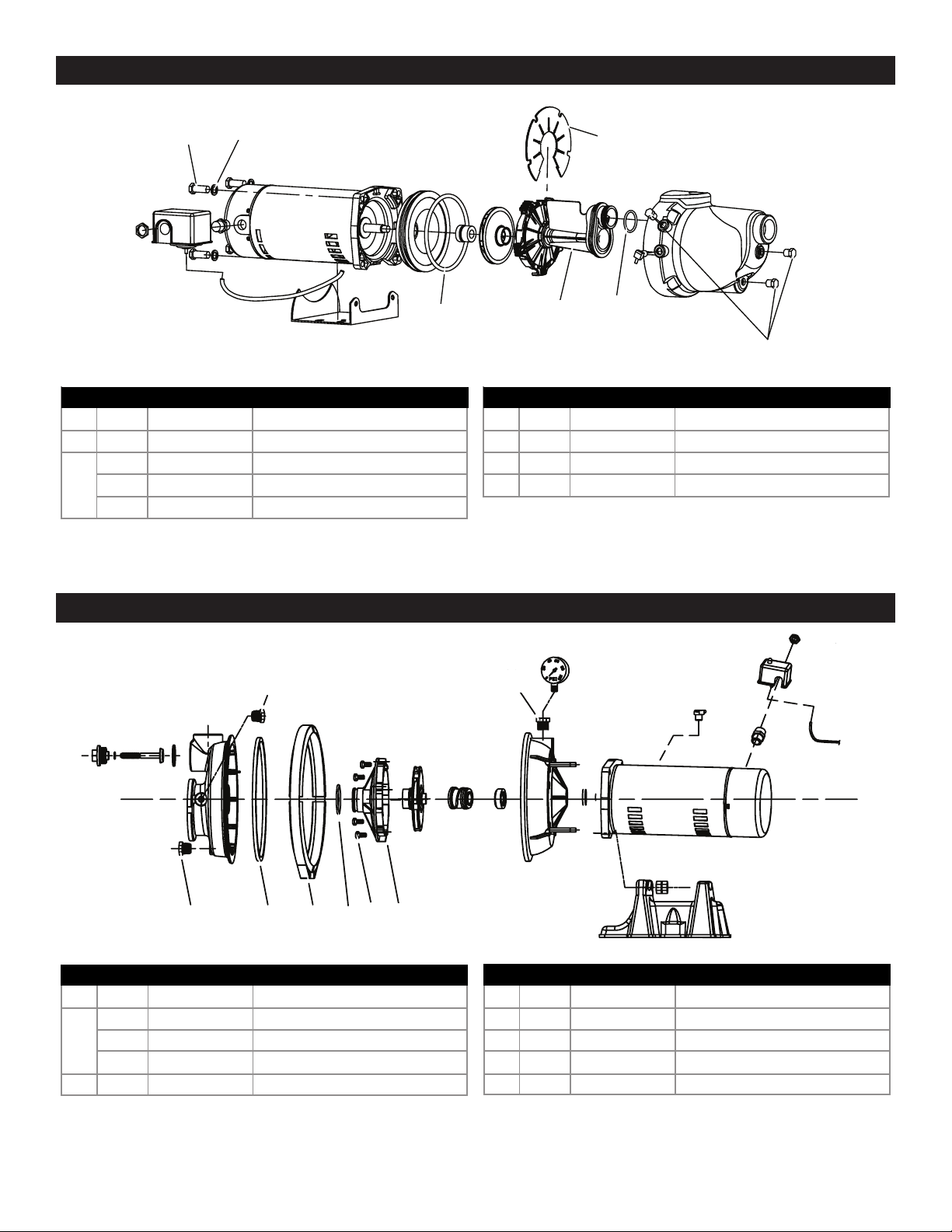
NO. QUANTITY PART NUMBER DESCRIPTION
1 3 EFSWJ5P01 Plug
2 1 EFSWJ5P04 O-Ring
1 EFSWJ5P05 Diffuser for 1/2 HP
3 1 EFSWJ7P06 Diffuser for 3/4 HP
1 EFSWJ7P06 Diffuser for 1 HP
NO. QUANTITY PART NUMBER DESCRIPTION
4 1 EFSWJ5P08 O-Ring
5 4 EFSWJ5P15 Screw
6 4 EFSWJ5P16 Washer
7 1 EFSWJ5P18 Plate
13
SHALLOW WELL PUMP REPAIR PARTS
CONVERTIBLE WELL PUMP REPAIR PARTS
NO. QUANTITY PART NUMBER DESCRIPTION
1 1 EFCWJ5P13 Adapter
1 EFCWJ6P15 Diffuser for 1/2 HP
2 1 EFCWJ7P15 Diffuser for 3/4 HP
1 EFCWJ7P15 Diffuser for 1 HP
3 4 EFCWJ5P16 Bolts
NO. QUANTITY PART NUMBER DESCRIPTION
4 1 EFCWJ5P17 O-Ring
5 1 EFCWJ5P18 Clamp
6 1 EFCWJ5P19 O-Ring
7 1 EFCWJ5P21 Plug
8 1 EFCWJ5P22 Plug
1
2
3
4
5
6 7
8
14
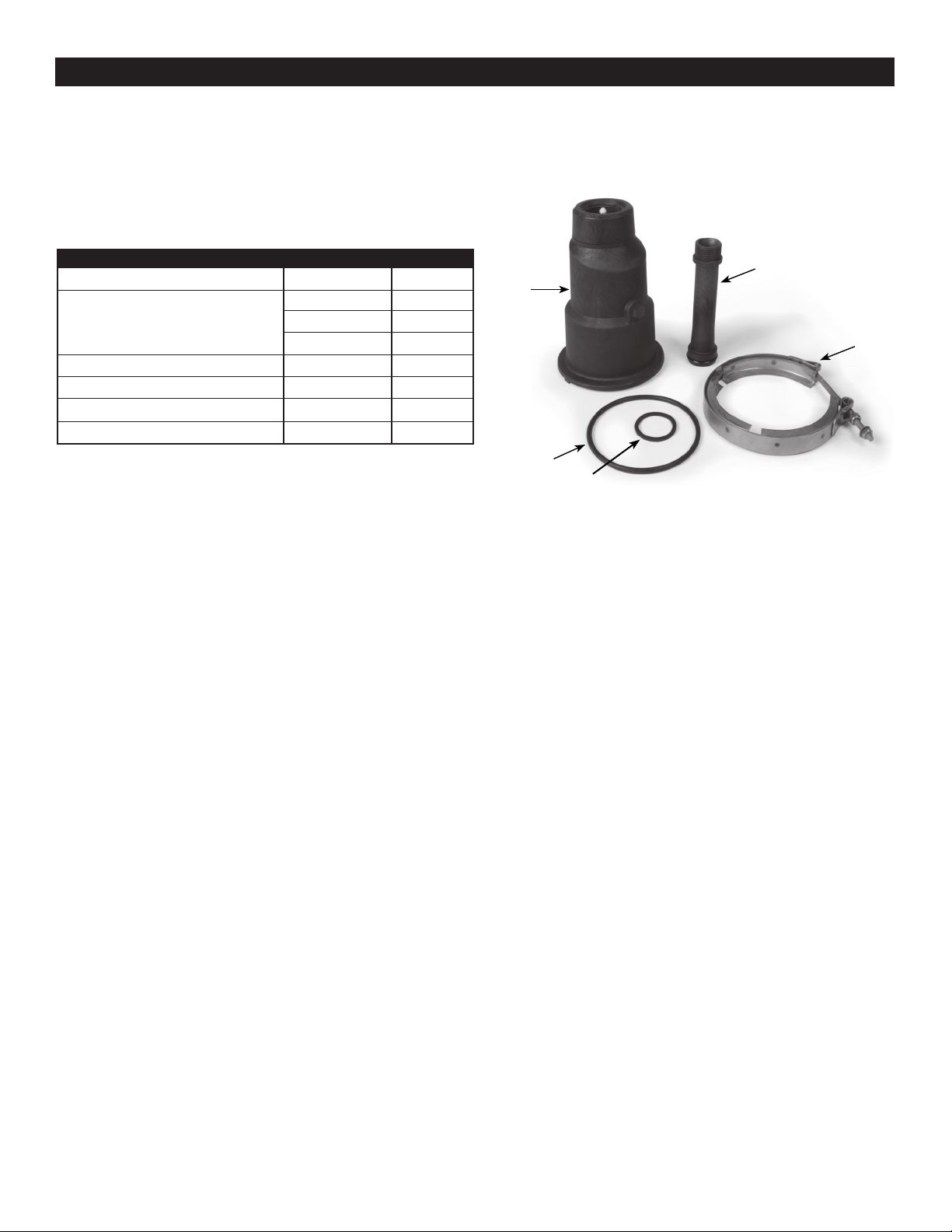
EJECTOR PACKAGES
Replacement parts are available for ejector kits - see parts list below.
1
WAPJCW (Plastic) Series
Shallow Well
Item Description P/N Identifying No.
Ejector Body EFCWJ5P35 1
EFCWJ5P29 2 (1/2HP)
Tube EFCWJ7P29 2 (3/4HP)
EFCWJ1P29 2 (1HP)
Clamp EFCWJ5P35 3
O-Ring EFCWJ5P27 4
O-Ring EFCWJ5P37 5
2
4
5
3

15
Retain Original Purchase Receipt for Warranty Eligibility
Limited Warranty
Manufacturer warrants to the original consumer purchaser (“Purchaser” or “You”) that its products are free from defects in
material and workmanship for a period of twelve (12) months from the date of the original consumer purchase. If, within
twelve (12) months from the original consumer purchase, any such product shall prove to be defective, it shall be repaired
or replaced at manufacturer’s option, subject to the terms and conditions set forth herein. Note that this limited warranty
applies to manufacturing defects only and not to ordinary wear and tear. All mechanical devices need periodic parts and
service to perform well. This limited warranty does not cover repair when normal use has exhausted the life of a part or
the equipment.
The original purchase receipt and product warranty information label are required to determine warranty eligibility. Eligibil-
ity is based on purchase date or original product – not the date of replacement under warranty. The warranty is limited to
repair or replacement of original purchased product only, not replacement product (i.e. one warranty replacement allowed
per purchase).
Purchaser pays all removal, installation, labor, shipping, and incidental charges.
Claims made under this warranty shall be made by contacting and returning the product to the factory immediately after
the discovery or any alleged defect. Manufacturer will subsequently take corrective action as promptly as reasonably pos-
sible. No requests for service will be accepted if received more than 30 days after the warranty expires. Warranty is not
transferable and does not apply to products used in commercial/rental applications.
General Terms and Conditions; Limitations of Remedies
You must pay all labor and shipping charges necessary to replace product covered by this warranty. This warranty does
not apply to the following: (1) acts of God; (2) products which, in manufacturer’s sole judgment, have been subject to
negligence, abuse, accident, misapplication, tampering, or alteration; (3) failures due to improper installation, operation,
maintenance or storage; (4) atypical or unapproved application, use or service; (5) failures caused by corrosion, rust or
other foreign materials in the system, or operation at pressures in excess of recommended maximums.
This warranty sets forth manufacturer’s sole obligation and purchaser’s exclusive remedy for defective products.
MANUFACTURER SHALL NOT BE LIABLE FOR ANY CONSEQUENTIAL, INCIDENTAL, OR CONTINGENT DAMAGES
WHATSOEVER. THE FOREGOING LIMITED WARRANTIES ARE EXCLUSIVE AND IN LIEU OF ALL OTHER EXPRESS
AND IMPLIED WARRANTIES, INCLUDING BUT NOT LIMITED TO IMPLIED WARRANTIES OF MERCHANTABILITY
AND FITNESS FOR A PARTICULAR PURPOSE. THE FOREGOING LIMITED WARRANTIES SHALL NOT EXTEND
BEYOND THE DURATION PROVIDED HEREIN.
Some states do not allow the exclusion or limitation of incidental or consequential damages or limitations on how long an
implied warranty lasts, so the above limitations or exclusions may not apply to You. This warranty gives You specic legal
rights and You may also have other rights which vary from state to state.
WARRANTY
1899 Cottage Street
Ashland, Ohio 44805
Telephone: 1-844-394-2604