Installation, Operation and Maintenance Manual
Installation
Location Requirements
The location selected for the ice machine head section must meet the following criteria. If any of these criteria are not met, select another location.
- The location must be indoors and must be free of airborne and other contaminants.
- The location must not be near heatgenerating equipment or in direct sunlight.
- The location must allow enough clearance for water, drain, and electrical connections in the rear of the ice machine.
- The location must not obstruct airflow through or around the ice machine
Installation Requirements
- The ice machine and bin must be level.
- Vent the ice machine and bin drains separately.
- Bin drain termination must have an air gap.
- The ice machine and bin must be descaled and sanitized after installation.
- The drain line must contain a union or other suitable means of disconnection at the ice machine.
QuietQube Models Only
- The ice machine top panel can be trimmed with an aviator snips to allow the line set, water line and electrical connections to exit the top. Only cut out what is needed, the back panel must support the top panel
- The water inlet and electrical connection must contain a service loop to allow future access.
Minimum/Maximum Temperatures

Ice Machine Heat of Rejection
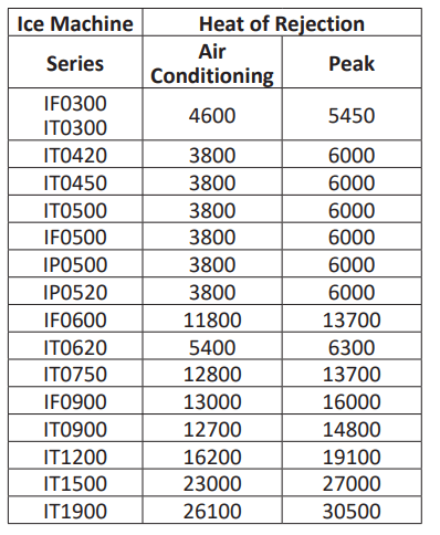
Use this information when:
- Sizing air conditioning equipment where self-contained air-cooled ice machines are installed.
- Determining the load on a cooling tower. Use the peak figure for sizing the load.
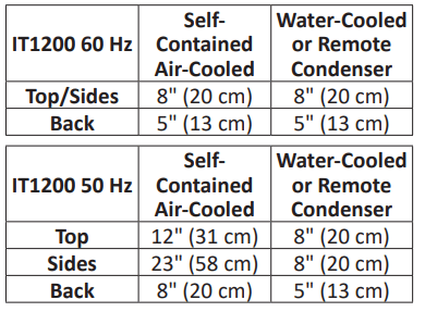
Clearance Requirements
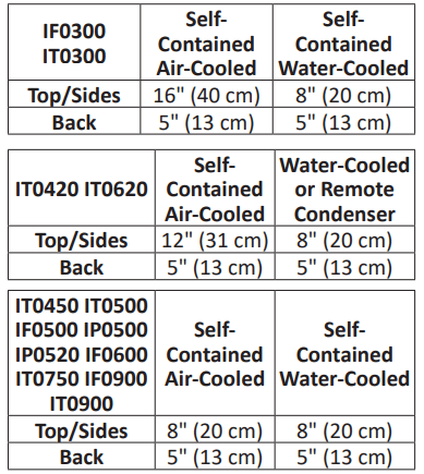
NOTE: Top air discharge kits require the same clearance requirements as the comparable self-contained air-cooled model.

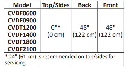
QuietQube Model Clearance Requirements

Condensing Unit Clearance Requirements
Air Baffle
Self-Contained Air-cooled Only
The air-cooled baffle prevents condenser air from recirculating.
To install:
1. Loosen the back panel screws next to the condenser.
2. Align the keyhole slots in the air baffle with the screw holes and slide the baffle down to lock in place.
Bin Installation Requirements
- The installation area must be capable of supporting the combined weight of the equipment and product.
- All ice machines installed on a bin require an ice deflector.
- Manitowoc bins have a deflector installed and require no modifications when used with a forward-facing evaporator.
- Ice machines with multiple evaporators require a deflector kit.
- Align sides and back of ice machine with sides and back of bin when placing ice machine on bin.
- Optional sales kits are available to adapt various sized or multiple ice machines on large bins.
Bin Installation
NOTE: When using casters, the units must be tethered or secured to comply with all applicable codes. Swivel casters must be mounted on the front and rigid casters must be mounted on the rear. Lock the front casters after installation is complete
1. Remove threaded plug from drain fitting.
2. Screw the leveling legs onto the bottom of the bin.
3. Screw the foot of each leg in as far as possible.
4. Move the bin into its final position.
5. Level the bin to assure that the bin door closes and seals properly. Use a level on top of the bin. Turn the base of each foot as necessary to level the bin.
6. Inspect bin gasket prior to ice machine installation. (Manitowoc bins come with a closed cell foam gasket installed along the top surface of the bin.)
7. Remove all panels from ice machine before lifting and installing on bin. Remove front panel, top cover, left and right side panels.
Dispenser Installation
Observe following recommendations unless required by the dispenser manufacturer.
- An adapter is not required for ice machines that match the dispenser size.
- A deflector is not required
- Ice level management is recommended to prevent water leakage or movement of ice machine during agitation.
- Align sides and back of ice machine with sides and back of dispenser when placing ice machine.
- Follow ice machine installation procedures in this manual and any additional installation requirements specified by the dispenser manufacturer
Electrical Requirements
All electrical work, including wire routing and grounding, must conform to local, state and national electrical codes. The following precautions must be observed:
- The ice machine must be grounded.
- A separate fuse/circuit breaker (dedicated circuit) must be provided for each ice machine head section, condenser or condensing unit.
- A qualified electrician must determine proper wire size dependent upon location, materials used and length of run (minimum circuit ampacity can be used to help select the wire size)
Voltage
The maximum allowable voltage variation is +10% / -5% of the rated voltage at ice machine start-up (when the electrical load is highest).
Fuse/Circuit Breaker
A separate electrical disconnect, which disconnects all poles and has 3 mm (1/8") contact separation, must be provided for fixed wiring. Circuit breakers must be H.A.C.R. rated in USA
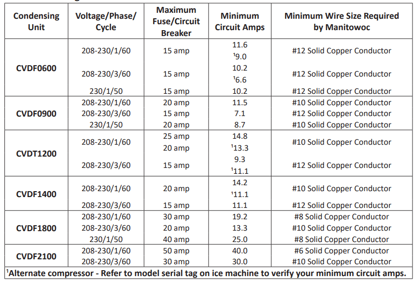
Minimum Circuit Ampacity
The minimum circuit ampacity is used to help select the wire size of the electrical supply. (Minimum circuit ampacity is not the ice machine’s running amp load.) The wire size (or gauge) also depends on location, materials used, length of run, etc., so it must be determined by a qualified electrician.
Ground Fault Circuit Interrupter
We do not recommend the use of a GFCI/ GFI circuit protection with our equipment. If a GFCI/GFI is required by code, use a GFCI/GFI breaker rather than an outlet, which is more prone to intermittent nuisance trips than panel circuit breakers.
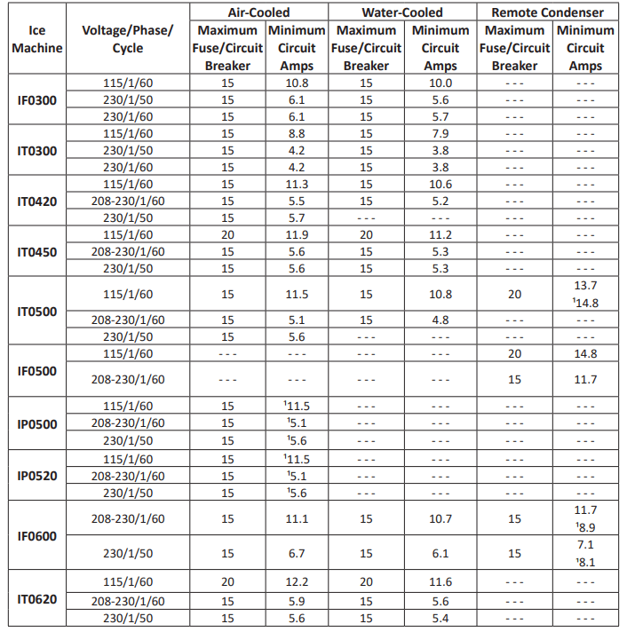
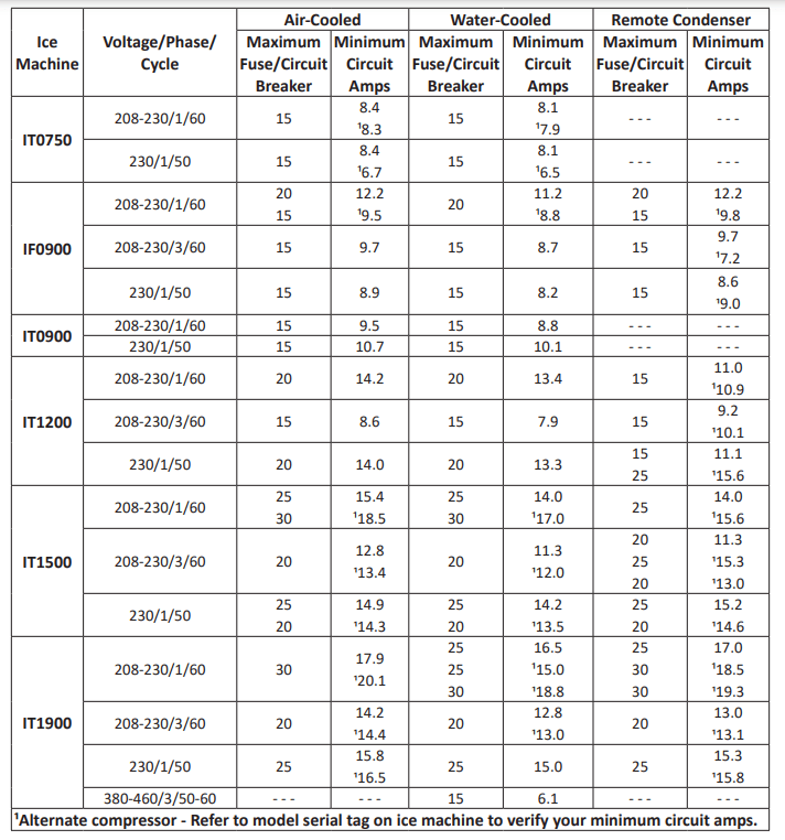
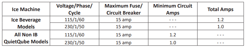
Maximum Breaker Size & Minimum Circuit Amperage Chart
NOTE: Due to continuous product improvements, this information is for reference only. Please refer to the ice machine data plate to verify electrical data. Model/Serial data plate information overrides information listed on this page.
QuietQube Head Sections
CVD Condensing Units
Water Connections
- Local water conditions may require treatment of the water to inhibit scale formation, filter sediment, and remove chlorine odor and taste.
- Connect ice making water inlet to potable water only.
- Install a water shut-off valve for potable water and water cooled condenser lines.
- Do not connect the ice machine to a hot water supply. Verify hot water restrictors installed on other equipment are functioning correctly. (Check valves on sink, faucets, dishwashers, etc.)
- Install a water regulating valve if water pressure exceeds the maximum valve rating.
- Insulate water and drain lines to prevent condensation.
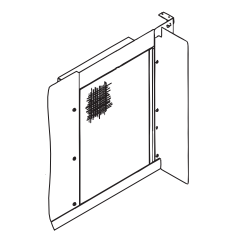
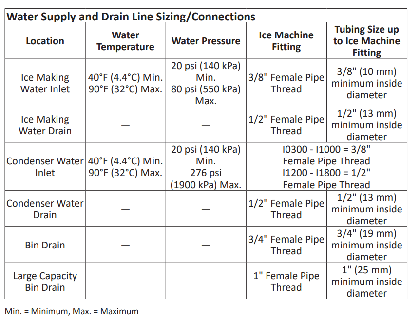
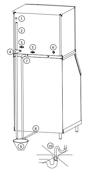
Water Supply and Drain Connections
| Item |
Description |
| 1 |
Electrical Entrance |
| 2 |
Vent Tube - Minimum Height 18" (46 cm) |
| 3 |
Potable Water Inlet - 3/8" FPT |
| 4 |
Potable Water Drain - 1/2" FPT |
| 5 |
Condenser Water Outlet - 1/2" FPT Water-cooled Models Only Install Separate Drain When Used |
| 6 |
Condenser Water Inlet See “Condenser Water Inlet” on page 22 for fitting sizes |
| 7 |
Base Drain - 1/2" CPVC Socket |
| 8 |
Bin Drain - See “Bin Drain” on page 22 for fitting sizes |
| 9 |
Floor Drain - Open and Trapped |
| 10 |
Do Not Trap Drain Line - Leave Air Gap Between Drain Line and Floor Drain |
AIR GAP
A greater than 1-inch air gap is built into the ice machine for back-flow prevention. This air gap exceeds NSF 12 requirements for back-flow prevention.

Cooling Tower Applications (Water-Cooled Models)
A water cooling tower installation does not require modification of the ice machine.
- Water pressure at the condenser cannot exceed 276 psig (1900 kPa).
- Water entering the condenser must not exceed 90°F (32°C).
- Water flow through the condenser must not exceed 5 gallons (19 liters) per minute.
- Allow for a pressure drop of 7 psi (50 kPa) between the condenser water inlet and the outlet of the ice machine.
- Water exiting the condenser must not exceed 110°F (43°C)
Drain Connections
Follow these guidelines when installing drain lines to prevent drain water from flowing back into the ice machine and storage bin:
- Drain lines must have a 1.5 inch drop per 5 foot (2.5 cm per meter) of run and must not create traps.
- The floor drain must be large enough to accommodate drainage from all drains.
- Run separate bin and ice machine drain lines. Insulate them to prevent condensation.
- Install a tee at the ice machine drain outlet and install an 18" (46 cm) vent above the drain line.
- Drain termination must have an air gap that meets local code.
Auxiliary Base Drain Installation
An auxiliary drain is located in the ice machine base to remove moisture in high humidity areas.
1. View the back of the ice machine base on the compressor side and locate and remove the cap plug.
2. Route tubing to an open site drain:
Use 1/2 inch CPVC tubing.
- Apply a bead of silicone around the exterior of the ice machine tubing and insert into ice machine base. The silicone will secure the tubing and provide a watertight seal.
- Provide support for tubing.
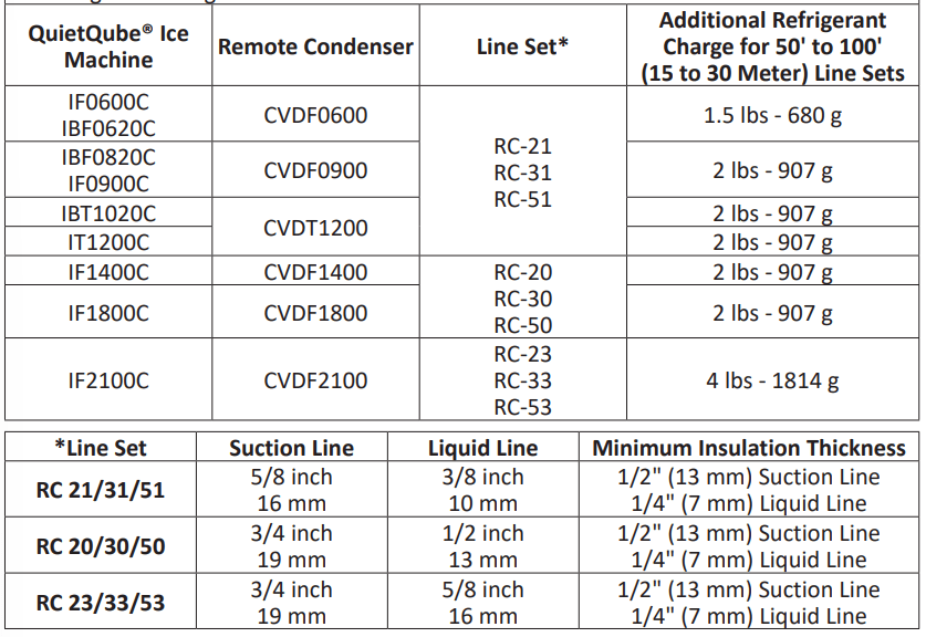
Remote Condenser and Condensing Unit Refrigeration System Installation
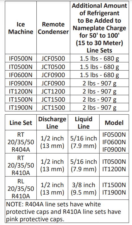
Each ice machine head section ships from the factory with a refrigerant charge appropriate for the entire system operation. The serial tag on the ice machine indicates the refrigerant charge.
Remote Condenser Models
CALCULATING INSTALLATION DISTANCES
Line Set Length
The maximum tubing length is 100 feet (30 meters).
Line Set Rise/Drop
The maximum rise is 35 feet (10.7 meters).
The maximum drop is 15 feet (4.5 meters).
Calculated Line Set Distance
The maximum calculated distance is 150 feet (45 meters). Line set rises, drops, horizontal runs (or combinations of these) in excess of the stated maximums will exceed compressor start-up and design limits. This will cause poor oil return to the compressor. Make the following calculations to make sure the line set layout is within specifications.
1. Insert the measured rise into the formula below. Multiply by 1.7 to get the calculated rise.
2. Insert the measured drop into the formula below. Multiply by 6.6 to get the calculated drop.
3. Insert the measured horizontal distance into the formula below. No calculation is necessary
4. Add together the calculated rise, calculated drop, and horizontal distance to get the total calculated distance. If this total exceeds 150 feet (45 meters), move the condenser/ condensing unit to a new location and perform the calculations again.
Maximum Line Set Distance Formula
Step 1. Measured Rise (R) 35 feet (10.7 meters)
Maximum _____ x 1.7 = _____ Calculated Rise
Step 2. Measured Drop (D) 15 feet (4.5 meters)
Maximum_____ x 6.6 = _____ Calculated Drop
Step 3. Measured Horizontal Distance (H) 100 feet (30 meters)
Maximum _____ Horizontal Distance
Step 4. Total Calculated Distance 150 feet (45 meters)
Maximum _____ Total Calculated Distance
REMOTE CONDENSER MODELS
Step 1 Secure the Condenser.
Through-holes are provided to secure the condenser to a curb, rack or wooden timber
Step 2 Route the Refrigeration Tubing.
Route the refrigeration tubing between the ice machine head section and the condenser.
- Maximum line set exposed on rooftop is 25% of total line set length.
- A qualified person must perform all roof penetrations.
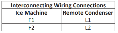
- Interconnecting wire must be routed between the ice machine and condenser.
Step 3 Connect the Line Set.
In most cases, by routing the line set properly, shortening will not be necessary.
When shortening or lengthening is required, do so before connecting the line set to the ice machine or the remote condenser. This prevents the loss of refrigerant in the ice machine or condenser. The quick connect fittings on the line sets are equipped with access valves. Use these valves to recover any vapor charge from the line set
When lengthening or shortening lines, follow good refrigeration practices, purge with nitrogen and insulate all tubing. Do not change the tube sizes. Evacuate the lines and place about 5 oz (145 grams) of vapor refrigerant charge in each line.
1. Remove the dust caps from the line set, condenser and ice machine.
2. Apply refrigeration oil to the threads on the quick-disconnect couplers before connecting them to the condenser.
3. Carefully thread the female fitting to the condenser or ice machine by hand, then tighten the couplings with a wrench until they bottom out.
4. Turn an additional quarter turn to ensure proper brass-to-brass seating. Torque to the following specifications:
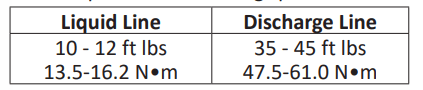
5. Check all fittings and valve caps for leaks and reinstall and tighten caps.
6. Interconnecting line voltage wiring is used to energize and de-energize the condenser fan motor. The remote condenser voltage matches the ice machine head section voltage.
Installation is finished for remote condenser models. Proceed to page 32 for start-up procedure.
QUIETQUBE MODELS
Step 1 Secure the Condensing Unit.
Through-holes are provided to secure the condensing unit to a curb, rack or wooden timber.
Step 2 Route the Refrigeration Tubing.
Route the refrigeration tubing between the ice machine head section and the condenser or CVD condensing unit.
- A suction line oil trap is required when rise is more than 20 feet (6 meters).
- Only one trap is allowed in the line set.
- Shorten the line set as required, do not coil line set.
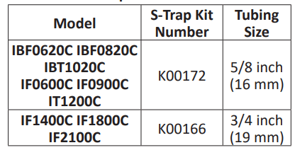
Manitowoc S-Trap Kit
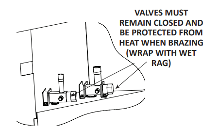
- Maximum amount of time the refrigeration system can be exposed to the atmosphere is 15 minutes. • Purge line set with dry nitrogen while brazing
- Shutoff valves for the line set on the ice machine must remain closed and be protected from heat during brazing.
- The condensing unit ships with a 50/50 mixture of nitrogen/helium.
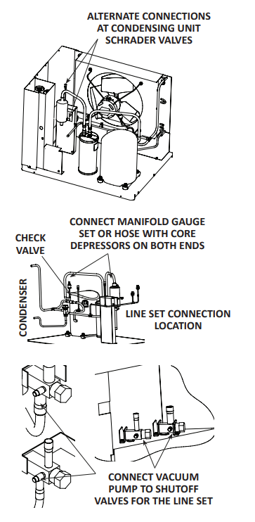
Step 3 Pressure Test and Evacuate Line Set and CVD Condensing Unit
- Shutoff valves for the line set must remain closed until pressure testing and evacuation are complete.
- Valve core removal tools that allow for removal and installation of the valve cores without removing hoses for the manifold gauge set are recommended to decrease the evacuation time.
- Pressure test at 150 psi (1000 kPa) for a minimum of 15 minutes.
- Minimum evacuation level is 500 microns.
Pressure test the line sets and CVD Condensing Unit with 150 psi (1000 kPa) of dry nitrogen. Add nitrogen at the shutoff valves for the line set located at the back of the ice machine head section or from the access valves located in the CVD Condensing Unit. Complete the pressure test, verify no leaks are present and remove the nitrogen from the system before connecting the vacuum pump. Connect vacuum pump and evacuate system to 500 microns.
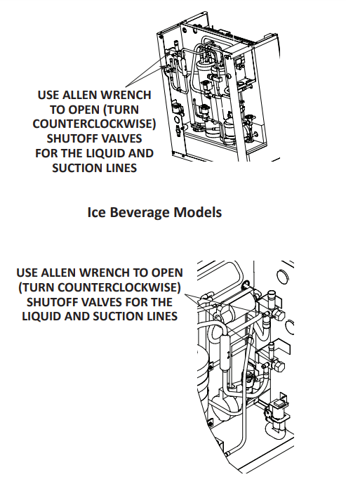
Step 4 Open Valves for the Line Set and Receiver
You will not hear refrigerant flow when the valves are opened. Refrigerant will not flow until the ice machine is started and the solenoid valve opens
- All valve caps must be reinstalled, tightened and leak-checked to assure no refrigerant leakage exists.
- Counterclockwise opens all valves. Open the shutoff valves for the suction and liquid lines

Step 5 Leak-Check the Refrigeration System.
A. Connect power to the ice machine head section - Do not connect power to the CVD condensing unit.
B. Press the power switch and energize the ice machine for 60 seconds to equalize pressures.
C. Disconnect power to the ice machine head section.
D. Leak-check line set connections, S trap and all factory joints in head section and condensing unit.
E. Connect power to the CVD condensing unit and allow system to pump down.
Step 6 Insulation Requirements.
- To prevent condensation, the entire suction line, including the shutoff valve, must be insulated.
- All insulation must be airtight and sealed at both ends.
The following insulation requirements prevent condensation at 90° F (32°C) ambient temperature and 90% relative humidity. If higher humidity is expected, increase insulation thickness:

Step 7 Insulation for the Suction Shutoff Valve.
The insulation for the suction shutoff valve is located in the plastic bag taped to the water curtain.
Step 8 Ice Beverage Models Only.
The thermostat probe must be moved from the shipping position to the ice-making position.
- The bin thermostat probe must be rotated down to enable ice contact and proper operation
- Verify probe wire does not interfere with the water curtain.
- The control is preset and does not require programming.
1. Loosen thumbscrew securing probe.
2. Rotate the probe from horizontal to vertical position.
3. Tighten thumbscrew to secure probe.
Starting the Ice Machine
Starting the ice machine and completing the Operational Checks are the responsibilities of the owner/operator. Adjustments and maintenance procedures outlined in this manual are not covered by the warranty.
REMOVE ICE THICKNESS PROBE SHIPPING BRACKETS
Remove and discard shipping brackets before starting the ice machine
Step 1 Ice machine must be programmed refer to “Setup Wizard” on page 37 for details.
Step 2 Refer to “Descaling and Sanitizing” on page 43 and clean and sanitize the ice machine and bin before placing in operation.
Step 3 Refer to “Ice Making Sequence of Operation” on page 39 for operational details.
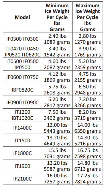
MINIMUM/MAXIMUM SLAB WEIGHT
Adjust ice thickness to maintain the correct bridge thickness and “Minimum/Maximum Slab Weight” on page 41.
Operation
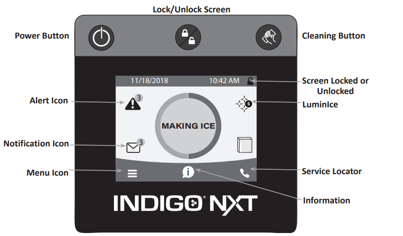
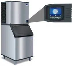
Touch Screen Features
The Indigo® NXT control panel offers a series of pressure-sensitive buttons and an interactive touchscreen.
Buttons
Power Button: Provides On/Off functions for the ice machine.
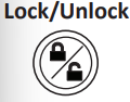
Lock/Unlock Button: Allows or prevents touchscreen navigation.
Cleaning Button: Initiates a cleaning cycle. Refer to Section 4 for details.
Touchscreen
Home screen allows viewing of ice machine status, alerts and messages. Navigation with the touchscreen provides access to menu items, machine information, settings and event logs. Setup and Energy Saver settings can be adjusted along with access to service and troubleshooting information.
Icons: Provide status indication and allow navigation by pressing the icon.
HOME SCREEN ICON DESCRIPTIONS
| Icon |
Description |
|

|
Center portion of the screen displays the current condition of the ice machine - Making ice, bin full, program mode or machine off |
|

|
Alert icon with number of messages. Pressing this icon will display the alert log which will allow viewing and resetting of alerts |
|

|
Notification icon with quantity of messages. Pressing this icon will display the routine maintenance reminder screen which will allow viewing and resetting of the reminder |
|

|
Menu icon will take you to the main menu |
|

|
Information icon provides model and serial number, installation date and other information specific to the ice machine |
|
|
Provides contact information for your local service support - Default is the Manitowoc Ice website service locator |
|
|
Indicates if screen is locked or unlocked |
|

|
Only visible when a LuminIce® II accessory is connected.
Blue S - Normal operation
Red S - Replace bulb
Red/Blue alternating - Incorrect bulb installed
|
|
Performance Specifications
NOTE: The performance statistics are calculated based on the performance of the machine at 90 degree ambient temperature and 70 degree water temperature. The actual statistics may vary depending on your operating conditions.
|
Setup Wizard
Screens will automatically advance after a selection is made or press the right arrow to advance one screen, press left arrow to go back one screen. All settings can be accessed and changed without the wizard by using menu screen navigation.
| Setup |
Description |
| Press ON/ OFF Button |
On/Off button is used to start/stop ice making. |
| Enter Model Number |
Only visible if model number can not be automatically identified. The ice machine will not start without model identification. |
| Select Language |
Default is English. Scroll to select a different language |
| Start Wizard |
Setup wizard will guide ice machine programming |
| Accessory Detection |
Detects if Ice Level Sensor, LuminIce II or AuCS are connected. Checkmark = yes - X = no |
| USB Setup |
Only used when setup features have been transferred to a USB drive. Skip screen by selecting right arrow. |
| Configure Date and Time Formats |
Select Month/Day/Year or Day/Month/Year. Select 12 hour or 24 hour time format |
| Set Time |
Use arrows to set local time. |
| Set Date |
Use arrows to set date for your location. |
| Units |
Select standard or metric |
| Brightness |
Configure screen brightness during normal operation. |
| Ice Program |
Program ice machine run times or press right arrow to skip this setup. |
| Cleaning Reminder |
Set descale or sanitize reminder or press right arrow to skip |
| IAuCS Only when detected |
Set frequency of operation when this accessory is installed. |
| Air Filter Air-cooled models only |
Set to ON for self-contained air cooled models. |
| Water Usage |
Factory default or Use less water for reverse osmosis systems or Use more water to improve clarity for unfiltered water |
| Water Filter |
Select Yes or No |
| LuminIce II Only when detected |
12 month reminder is automatically set. |
| Ice Level Sensor Only when detected |
Reminder to rotate the sensor from shipping to operational position. |
| Wizard Complete |
Press right arrow or home icon to return to home screen. |
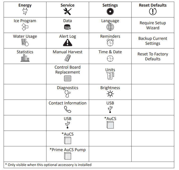
Menu Screen Navigation
Select SETTINGS Icon from the Home Screen to access Main Menu screen.
Ice Making Sequence of Operation
The power button must be depressed and the water curtain/ice dampers must be in place on the evaporator before the ice machine will start.
Water Purge Cycle
The ice machine purges any remaining water from the water trough down the drain. Prechill Cycle The refrigeration system cools the evaporator before the water pump is energized.
Freeze Cycle
Water flows across the evaporator and the refrigeration system chills the evaporator. Ice builds on the evaporator and the freeze cycle continues until the ice thickness probe senses a sheet of ice has formed. The ice thickness probe signals the control board to start a harvest.
Harvest Cycle
Any remaining water is purged down the drain as refrigerant gas warms the evaporator. When the evaporator warms, the sheet of cubes slides off the evaporator and into the storage bin. If all cubes fall clear of the water curtain (or ice damper) the ice machine starts another freeze cycle.
Off Cycle
If the water curtain or ice damper are held open by ice cubes the ice machine shuts off. When the water curtain or ice damper closes, the ice machine starts a new cycle at the water purge.
Control Board Timers
The control board has the following nonadjustable timers:
- The ice machine control board will set its own install date after 100 freeze and harvest cycles.
- The ice machine is locked into the freeze cycle for 6 minutes before a harvest cycle can be initiated.
- The maximum freeze time is 35 minutes at which time the control board automatically initiates a harvest sequence.
- The maximum harvest time is 7 minutes, the control board will perform a water thaw cycle and then return the ice machine to the freeze cycle.
Service Faults
Service Faults are stored and indicated by the control board after three cycles. The number of cycles required to stop the ice machine varies for each Service Fault.
- Long Freeze Cycle - If the freeze time reaches 35 minutes, the control board automatically initiates a harvest cycle. If 6 consecutive 35 minute freeze cycles occur, the ice machine stops.
- Long Harvest Cycle - If the harvest time reaches 7 minutes, the control board automatically returns the ice machine to the freeze cycle. After 3 consecutive long harvest cycles the ice machine stops. Refer to Section 5 if you receive an alert for Service Fault E01 or E02.
Safe Operation Mode
Allows the ice machine to operate up to 72 hours if the ice thickness probe and/or water level probe sensors fail.
- When the control board starts the safe mode, an alert is flashed on the display to notify the end-user they have a production problem.
- The control board automatically initiates and monitors the safe mode. The control will automatically exit the safe mode if a normal signal is received from the input.
- After 72 hours, the control board will enter a standby mode and turn off.
Water Assist Harvest
When the damper/curtain does not open within 3.5 minutes in the harvest cycle the following occurs:
- 3.5 minutes - The water inlet valve energizes until water touches the high water level probe.
- 4 minutes - The water pump energizes.
- 6.5 to 7 minutes - The water dump valve energizes
Water Thaw Cycle
When the damper/curtain does not open during the 7 minute harvest cycle the following water thaw cycle occurs:
- 7 minutes - The compressor, harvest solenoid valve and dump valve deenergize.
1. The water pump remains energized and the water inlet valve energizes until water touches the high water level probe.
2. Water is circulated over the evaporator.
3. Water is circulated, dumped and refilled to the high water level probe for approximately 1 hour.
- At the end of the thaw cycle the ice machine will start another freeze cycle (approximately 1 - 1.75 hour).
Minimum/Maximum Slab Weight
Adjust ice thickness to meet chart specifications.
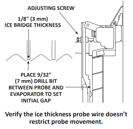
Ice Thickness Check
After a harvest cycle, inspect the ice cubes in the ice storage bin. The ice thickness probe is factory-set to maintain the ice bridge thickness at 1/8" (3 mm).
NOTE: Make sure the water curtain is in place when performing this check. It prevents water from splashing out of the water trough.
1. Inspect the bridge connecting the cubes. It must be approximately 1/8" (3 mm) thick.
2. If adjustment is necessary, turn the ice thickness probe adjustment screw clockwise to increase bridge thickness, counterclockwise to decrease bridge thickness. Set a 7 mm (9/32") gap between ice thickness probe and evaporator as starting point, then adjust to achieve a 1/8" (3 mm) bridge thickness.
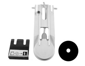
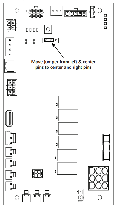
Reverse Osmosis or Deionized Water Usage
When using water with low total dissolved solid content (low TDS) the water level probe sensitivity can be increased by moving the jumper over one pin
The Electronic Control Board diagram shows the default position of the jumper covering the left and center pins. Moving the jumper to the center and right pins and enabling R.O. menu “Use less water with reverse osmosis” (Settings/Energy/ Water Usage/Use Less Water With Reverse Osmosis) will increase the sensitivity of the water level probe.
Maintenance
Descaling and Sanitizing
General
You are responsible for maintaining the ice machine in accordance with the instructions in this manual. Maintenance procedures are not covered by the warranty.
Descale and sanitize the ice machine every six months for efficient operation. If the ice machine requires more frequent descaling and sanitizing, consult a qualified service company to test the water quality and recommend appropriate water treatment. An extremely dirty ice machine must be taken apart for descaling and sanitizing.
Manitowoc Ice Machine Cleaner/Descaler and Sanitizer are the only products approved for use in Manitowoc ice machines.
Ice Machine Inspection
Check all water fittings and lines for leaks. Also, make sure the refrigeration tubing is not rubbing or vibrating against other tubing, panels, etc.
Do not put anything (boxes, etc.) in front of the ice machine. There must be adequate airflow through and around the ice machine to maximize ice production and ensure long component life.
Exterior Cleaning
Clean the area around the ice machine as often as necessary to maintain cleanliness and efficient operation.
Wipe surfaces with a damp cloth rinsed in water to remove dust and dirt from the outside of the ice machine. If a greasy residue persists, use a damp cloth rinsed in a mild dish soap and water solution. Wipe dry with a clean, soft cloth.
The exterior panels have a clear coating that is stain resistant and easy to clean. Products containing abrasives will damage the coating and scratch the panels.
- Never use steel wool or abrasive pads for cleaning.
- Never use chlorinated, citrus based or abrasive cleaners on exterior panels and plastic trim pieces.
Remedial Cleaning Procedure
- This procedure descales all components in the water flow path, and is used between the bi-yearly detailed descaling and sanitizing procedure
Detailed Descaling/Sanitizing Procedure
This procedure must be performed a minimum of once every six months.
Detailed Descaling and Sanitizing Procedure
Ice machine cleaner/descaler is used to remove lime scale and mineral deposits. Ice machine sanitizer disinfects and removes algae and slime.
Step 1 Open the front door to access the evaporator compartment. Ice must not be on the evaporator during the descaling/ sanitize cycle. Follow one of the methods below:
- Press the power switch at the end of a harvest cycle after ice falls from the evaporator(s).
- Press the power switch and allow the ice to melt.
Step 2 Remove all ice from the bin/ dispenser.
Step 3 Press the Clean button and select “Turn off when complete”. Water will flow through the water dump valve and down the drain. Wait approximately 1 minute until the water trough refills and the display indicates Add Chemical. Add the proper amount of ice machine cleaner/descaler to the water trough by pouring between the water curtain and evaporator, then confirm the chemical was added.
Step 4 Wait until the cycle is complete (approximately 24 minutes). Then disconnect power to the ice machine (and dispenser when used).
Step 5 Remove parts for descaling.
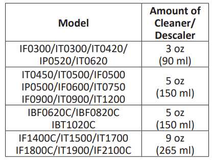
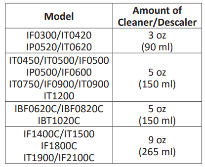
Step 6 Mix a solution of cleaner/descaler and lukewarm water. Depending upon the amount of mineral buildup, a larger quantity of solution may be required. Use the ratio in the table below to mix enough solution to thoroughly descale all parts.
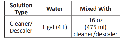
Step 7 Use half of the cleaner/descaler & water mixture to descale all components. Use caution not to expose electrical connectors to liquid and soak parts for 5 minutes (15 - 20 minutes for heavily scaled parts). The solution will foam when it contacts lime scale and mineral deposits; once the foaming stops, use a soft-bristle nylon brush, sponge or cloth (NOT a wire brush) to carefully descale the parts. When descaling is complete rinse all removed components with clean water
Step 8 While components are soaking, use half of the solution to descale all food zone surfaces of the ice machine and bin (or dispenser). Use a nylon brush or cloth to thoroughly descale the following ice machine areas:
- Side walls
- Base (area above water trough)
- Evaporator plastic parts - including top, bottom and sides
- Bin or dispenser
Rinse all areas thoroughly with clean water.
SANITIZING PROCEDURE
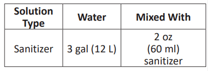
Step 9 Mix a solution of sanitizer and lukewarm water.
Step 10 Use half of the sanitizer/ water solution to sanitize all removed components. Fill a spray bottle and use caution not to expose electrical connectors to liquid and liberally apply the solution to all surfaces of the removed parts or soak the removed parts in the sanitizer/water solution. Do not rinse parts after sanitizing
Step 11 Use half of the sanitizer/water solution to sanitize all food zone surfaces of the ice machine and bin (or dispenser). Use a spray bottle to liberally apply the solution. When sanitizing, pay particular attention to the following areas:
- Side walls
- Base (area above water trough)
- Evaporator plastic parts - including top, bottom and sides
- Bin or dispenser
Do not rinse the sanitized areas.
Step 12 Replace all removed components back into their original configuration and wait 20 minutes.
Step 13 Press the Clean button and select “Make ice when complete”. Water will flow through the water dump valve and down the drain. Wait approximately 1 minute until the water trough refills and the display indicates Add
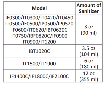
Chemical. Add the proper amount of ice machine sanitizer to the water trough by pouring between the water curtain and evaporator, then confirm the chemical was added.
Parts Removal for Detailed Descaling and Sanitizing
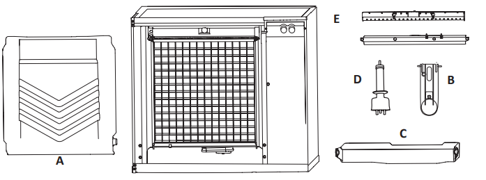
Single evaporator is shown; Each evaporator will have a distribution tube and water curtain/damper.
A. Remove the water curtain(s)
- Gently flex the curtain in the center and remove it from the right side.
- Slide the left pin out.
B. Remove the ice thickness probe
- Compress the hinge pin on the top of the ice thickness probe.
- Pivot the ice thickness probe to disengage one pin then the other. The ice thickness probe can be descaled and sanitized at this point without complete removal. If complete removal is desired, disconnect the ice thickness control wiring from the control board.
C. Remove the water trough
- Depress tabs on right and left side of the water trough.
- Allow front of water trough to drop as you pull forward to disengage the rear pins.
D. Remove the water level probe
- Pull the water level probe straight down to disengage.
- Lower the water level probe until the wiring connector is visible.
- Disconnect the wire lead from the water level probe.
- Remove the water level probe from the ice machine.
E. Remove the water distribution tube(s)
NOTE: Thumbscrews for the distribution tube are retained to prevent loss. Loosen thumbscrews, but do not pull thumbscrews out of distribution tube.
- Loosen the two outer screws (do not remove screws completely because they are retained to prevent loss) and pull forward on the distribution tube to release from slip joint.
- Disassemble distribution tube by loosening the two (2) middle thumbscrews and dividing the distribution tube into two pieces.
Remedial Cleaning Procedure
This procedure descales all components in the water flow path, and is used to descale the ice machine between the bi-yearly detailed descaling and sanitizing procedure.
Ice machine cleaner/descaler is used to remove lime scale and mineral deposits. Ice machine sanitizer disinfects and removes algae and slime.
Step 1 Ice must not be on the evaporator during the clean/sanitize cycle. Follow one of the methods below:
- Press the power switch at the end of a harvest cycle after ice falls from the evaporator(s).
- Press the power switch and allow the ice to melt
Step 2 Open the front door to access the evaporator.
Step 3 Press the Clean button and select “Make ice when complete”. Water will flow through the water dump valve and down the drain. Wait approximately 1 minute until the water trough refills and the display indicates Add Chemical. Add the proper amount of ice machine descaler to the water trough by pouring between the water curtain and evaporator, then confirm the chemical was added.
Step 4 Close and secure the front door. The ice machine will automatically start ice-making after the clean cycle is complete (approximately 24 minutes).
Cleaning the Air Filter and Condenser
The washable filter on self-contained ice machines is designed to catch dust, dirt, lint and grease. Clean the filter once a month with mild soap and water
A dirty condenser restricts airflow, resulting in excessively high operating temperatures. This reduces ice production and shortens component life.
Clean the condenser at least every six months.
- Shine a flashlight through the condenser to check for dirt between the fins.
- Blow compressed air or rinse with water from the inside out (opposite direction of airflow).
- If dirt still remains, call a service agent to clean the condenser.
Removal from Service/Winterization
All Models
1. Descale and sanitize the ice machine.
2. Turn off the water supply, disconnect and drain the incoming ice-making water line at the rear of the ice machine and drain the water trough.
3. Energize the ice machine, wait one minute for the water inlet valve to open and blow compressed air in both the incoming water and the drain openings in the rear of the ice machine to remove all water
WATER-COOLED MODELS ONLY
- Disconnect the incoming water and drain lines from the water-cooled condenser.
- Insert a large screwdriver between the bottom spring coils of the water regulating valve and pry open the Water Regulating Valve.
- Hold the valve open and blow compressed air through the condenser until no water remains.
All Models
4. Press the power switch and disconnect electrical power at the main disconnect/circuit breaker.
5. Fill spray bottle with sanitizer and spray all interior food zone surfaces. Do not rinse and allow to air dry.
6. Replace all panels.
Troubleshooting
Before Calling for Service Checklist
If a problem arises during operation of your ice machine, follow the checklist below before calling service. Routine adjustments and maintenance procedures are not covered by the warranty.
| Problem |
Possible Cause |
To Correct |
| Ice machine does not operate. |
No electrical power to the ice machine and/or condensing unit. |
Replace the fuse/reset the breaker/turn on the main switch. |
| |
High pressure cutout tripping |
Clean condenser coil. (See page 49) |
| |
Energy Saver or other field entered programming is stopping ice machine. |
Reset to factory defaults. |
| |
Water curtain off or stuck open. |
Water curtain must be installed and swinging freely |
| |
Ice machine is not turned on. |
Press power button, display must indicate “Making Ice”. |
| |
IB Models Only - Dispenser ice level thermostat is open. |
Adjust thermostat to maintain correct dispenser level. |
| Ice machine stops, and can be restarted by pressing the power switch. |
Service Fault feature stopping the ice machine. |
Refer to “Service Faults” on page 53. |
| Ice machine does not release ice or is slow to harvest |
Ice machine is dirty. |
Descale and sanitize the ice machine. (See page 43) |
| |
Ice machine is not level. |
Level the ice machine. |
| |
Low air temperature around ice machine head section. |
Air temperature must be at least 35° (2°C). |
| |
Fan cycle control does not deenergize condenser fan motor |
Call for service. |
| |
Water regulating valve incorrectly adjusted or will not close. |
Check for water at condenser drain outlet in harvest cycle. Contact a qualified service company to adjust/replace valve if water is present. |
| Ice machine does not cycle into harvest mode. |
The six-minute freeze time lock-in has not expired yet. |
Uneven ice fill (thin at the top of evaporator). |
| |
Ice thickness probe is dirty |
Descale and sanitize the ice machine. (See page 43) |
| |
Ice thickness probe is disconnected. |
Connect the probe to the control board. |
| |
Ice thickness probe is out of adjustment. |
Adjust the ice thickness probe. (See page 41) |
| |
Uneven ice fill (thin at the top of evaporator). |
Verify sufficient water level in sump trough. Contact a qualified service company to check refrigeration system. |
| Ice quality is poor (soft or not clear). |
Poor incoming water quality. |
Contact a qualified service company to test the quality of the incoming water and make appropriate filter recommendations. |
| |
Water filtration is poor |
Replace the filter |
| |
Ice machine is dirty. |
Descale and sanitize the ice machine. (See page 43) |
| |
Water dump valve is not working. |
Disassemble and clean the water dump valve. |
| |
Water softener is working improperly (if applicable). |
Repair the water softener. |
| Ice machine produces shallow or incomplete cubes, or the ice fill pattern on the evaporator is incomplete. |
Ice thickness probe is out of adjustment. |
Adjust the ice thickness probe. (See page 41) |
| |
Ice thickness probe is out of adjustment. |
Check the water level probe position. |
| |
Water inlet valve filter screen is dirty. |
Remove the water inlet valve and clean the filter screen. |
| |
Water filtration is poor. |
Replace the filter |
| |
Hot incoming water. |
Connect the ice machine to a cold water supply. (See page 22) |
| |
Water inlet valve is not working |
Replace the water inlet valve. |
| |
Incorrect incoming water pressure. |
Water pressure must be 20 psi - 80 psi (140 kPa - 550 kPa). |
| |
Ice machine is not level |
Level the ice machine. |
| Low ice capacity |
Water inlet valve filter screen is dirty |
Remove the water inlet valve and clean the filter screen |
| |
Incoming water supply is shut off. |
Open the water service valve. |
| |
Water inlet valve stuck open or leaking. |
Press the power button and turn off the ice machine, if water continues to enter water trough, replace the water inlet valve. |
| |
The condenser is dirty |
Clean the condenser. |
| |
High air temperature entering condenser. |
Refer to minimum/maximum air temperature chart for your model on page 14. |
| |
The harvest assist air compressor is not functioning |
Call for service. |
Service Faults
In addition to the standard safety controls, such as the high pressure cutout, your Manitowoc ice machine features builtin service faults which will stop the ice machine if conditions arise which could cause a major component failure.
Before calling for service, re-start the ice machine using the following procedure:
1. Press the power button. The display reads “Off”. Press the power button again, and the display reads “Making Ice”.
A. If a service fault has stopped the ice machine, it will restart after a short delay. Proceed to step 2.
B. If the ice machine does not restart, see “Ice machine does not operate” on page 51.
2. Allow the ice machine to run to determine if the condition repeats.
A. If the ice machine stops again, the condition has repeated. Call for service.
B. If the ice machine continues to run, the condition has corrected itself. Allow the ice machine to continue running.