INSTALLATION,USEANDMAINTENANCEINSTRUCTION
COMMERCIALINFORMATIONFORTHECONSUMER
GB
TECHNICALINFORMATION
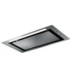
TYPE: FSLC
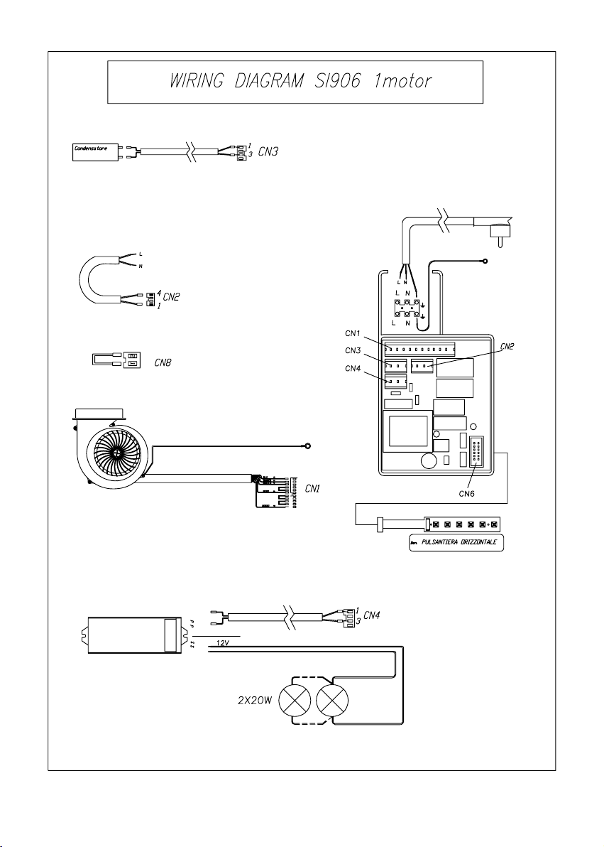
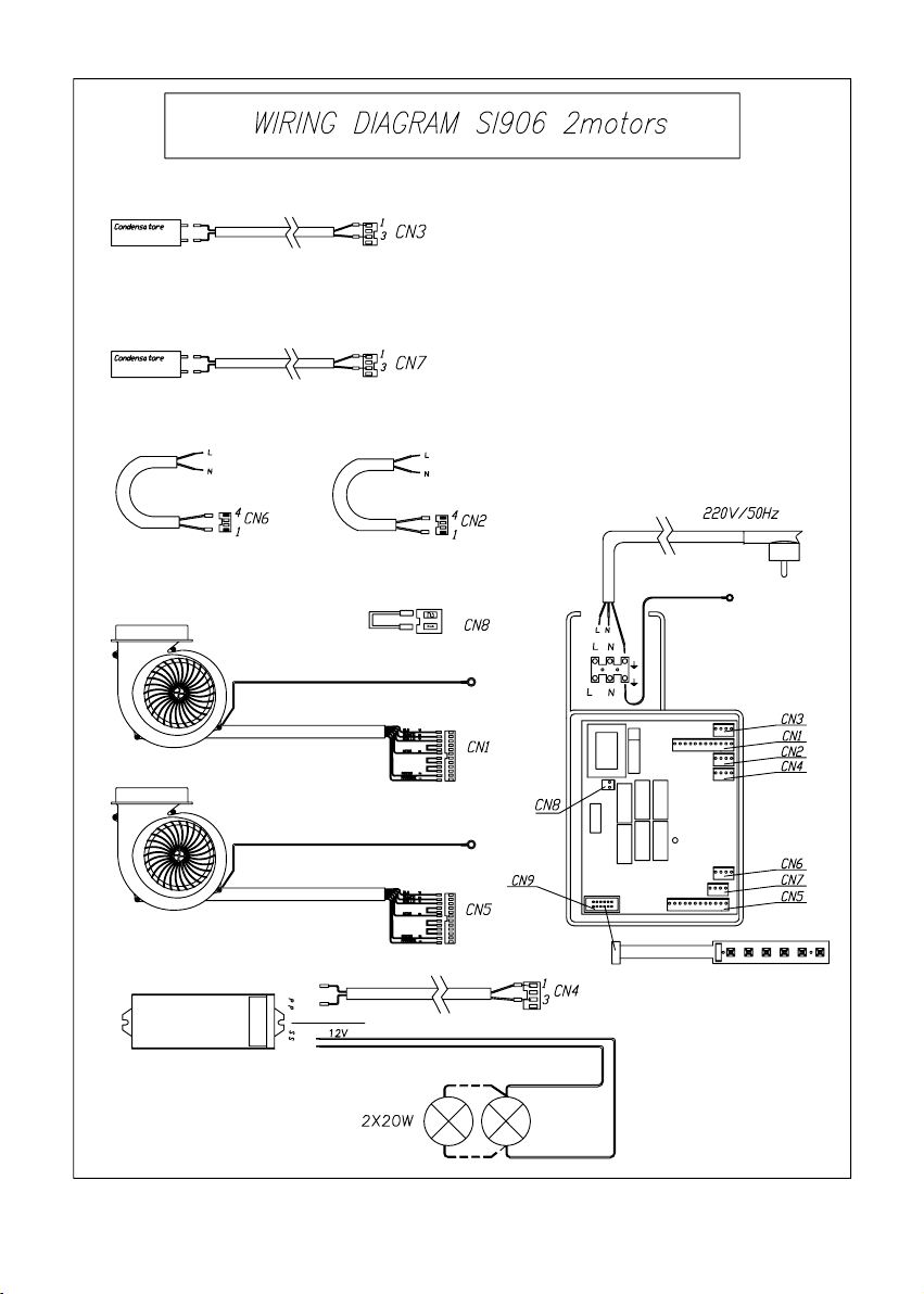
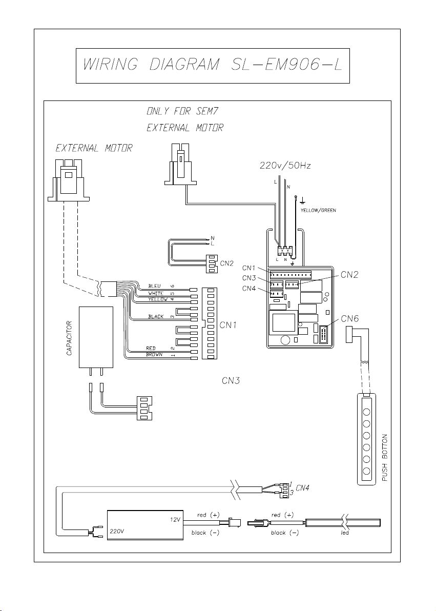
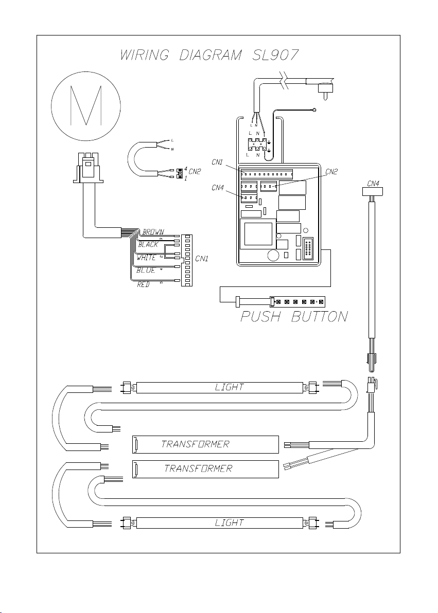
SL-EM906 / SL906 1Mot. / SL906 2Mot. /SL907
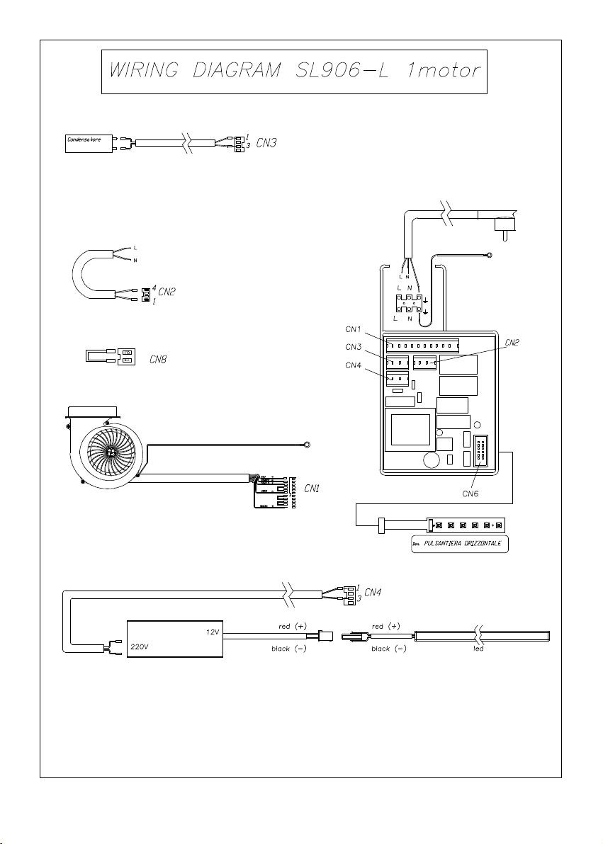
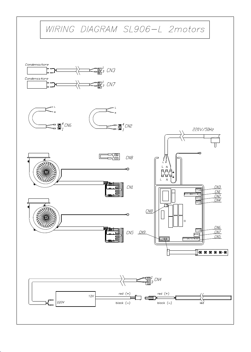
SL-EM906-L / SL906-L 1 MOT / SL906-L 2 MOT

2

3
Thesymbolontheproductoronitspackagingindicatesthatthisproductmaynotbe
treatedashouseholdwaste.Insteaditshallbehandedovertotheapplicablecollection
pointfortherecyclingofelectricalandelectronicequipment.Byensuringthisproduct
isdisposedofcorrectly,youwillhelppreventpotentialnegativeconsequencesforthe
environment and human health, which could otherwise be caused by inappropriate
wastehandlingofthisproduct.Formoredetailedinformationaboutrecyclingofthis
product,pleasecontactyourlocalcityoce,yourhouseholdwastedisposalserviceor
theshopwhereyoupurchasedtheproduct.Thisapplianceismarkedaccordingtothe
Europeandirective2002/96/EConwasteelectricalandelectronicequipment(WEEE).
GB

CONTENTS
Warnings
Uses
Installation
Working
Maintenance
4
GB

WARNINGS
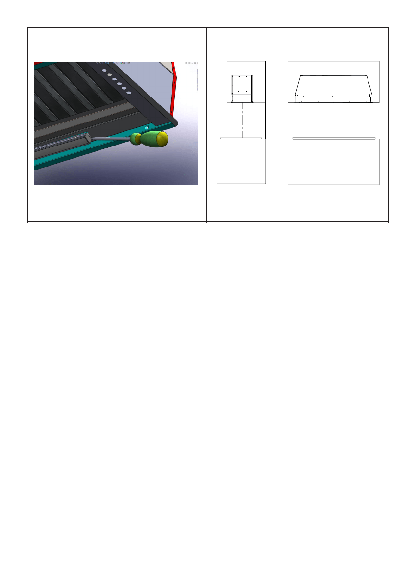
- The cooker surface and the inferior part of
the cooker hood must be at a minimun distan-
ce of 65 cm. To ensure good performances of
the product is recommended to install the hood
centrally with respect to the cook top (Fig.18).
- The air sucked can’t be conveyed throu-
gh or into a duct used to let out fumes
from appliances fed by energy other than
electric power (eg. centralized heating, ra-
diators, water-heaters, etc.).
- Attention: remove any possible pvc lm
from the stainless steel.
- To evacuate the air outlet, please comply
with the pertaining rules given by compe-
tent authorities.
- Provide the room with an adequate aeration
whenacookerhoodandappliancesfedbyener-
gyotherthanelectricpower(gas-,oil-,orcoal-
stoves, etc.) are used simultaneously. The coo-
kerhood,whenevacuatingthesuckedair,could
generateanegativepressureintheroom-which
can’t exceedthe limitof0.04mbar,inorderto
avoidthesuckofexhaustsderivingfromtheheat-
source. Therefore the room should be provided
withair-intakestoallowacostantowoffreshair.
Iftheratinglableinthecooker-hoodshows
thesymbol,theapplianceisbuiltinclass
II° and it does not need any earth connec-
tion.
If the rating lable in the cooker-hood does
not show the symbol , the appliance is
builtin class I°and it needsthe earth con-
nection.
-Whenperformingtheelectricalconnections
ontheappliance,pleasemakesurethatthe
current-tapisprovidedwithearthconnection
andthatvoltage valuescorrespondtothose
indicatedonthe label placed inside theap-
plianceitself.
-Before carrying outanycleaning or main-
tainingoperations,theapplianceneedstobe
removedfromtheelectricgrid.Iftheapplian-
ceisnotprovidedwithanon-separableexi-
blecableandplug,orwithanotherdevice
5
ensuringomnipolardisconnectionsfromthe
grid, with an opening distance between the
contactsofatleast3mm,thensuchdiscon-
nectingdevicesmust besupplied withinthe
xedinstallation.
Ifthexedapplianceisendowedwithasup-
plycordandaplug,theappliancehastobe
putinaplacewheretheplugcanbereached
easily.
- The use of materials which can burst
into ames should be avoided in close
proximity of the appliance. When frying,
please pay particular attention to re risk
due to oil grease. Being highly inamma-
ble, fried oil is especially dangerous. Do
not use uncovered electric grills. In order
to avoid possible re risk, all instructions
for grase-lter cleaning and for removing
eventual grease deposits should be strictly
followed.
USES
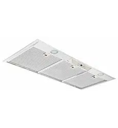
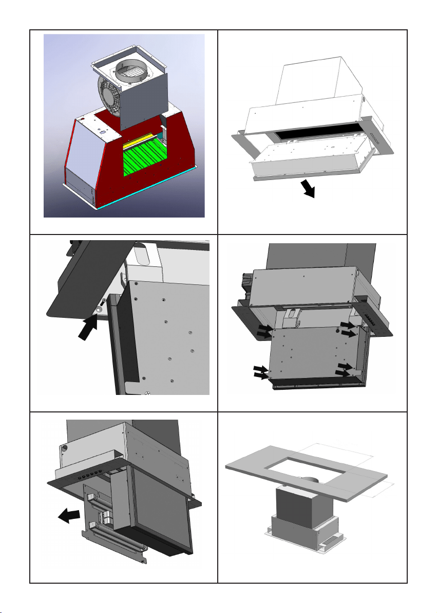
The appliance is already arranged both for
lteringandforsuctionperformances.
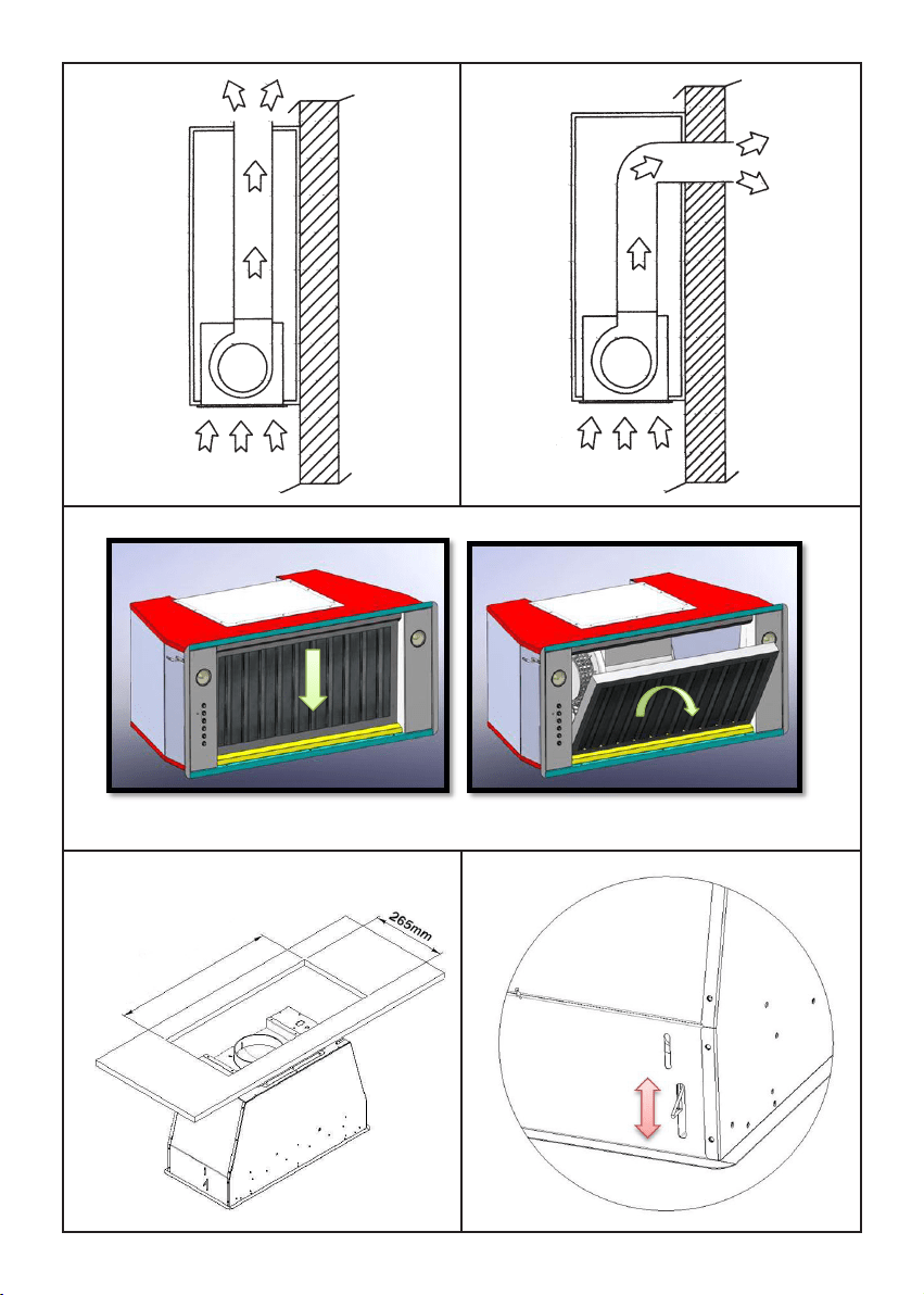
-In itsltering version (Fig.1),theair and
fumesconveyedbytheappliancearedepured
bothbyagreaselterandbyanactivecoal
lter,andputagainintocirculationthrough
theholemadeonthetopofthecabinet.
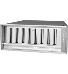
-Initssucking version(Fig.2),fumesaredi-
rectlyconveyedoutside,throughanevacua-
tionductconnectedwiththesuperiorpartof
thewallortheceiling.Bothcoallterandair
deectorarenotnecessaryinthiscase.
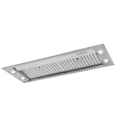
INSTALLATION SL906
Before installing the appliance, make sure
thatnoneofthepartsisdamagedinanyway.
Incaseofdamagedparts,contactyourretai-
leranddonotproceedwithinstallation.
Read all of the following instructions with
carebeforeinstallingtheappliance.
-Useanairoutletpipeoftheshortestpos-
siblelength.

6
-Limitthenumberofpipebends.
-Useamaterialapprovedbystandardsand
regulations.
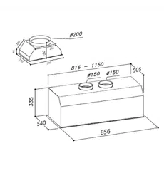
-Avoidanysuddenchangesinpipesection
(recommendedconstantdiameter:Ø150mm
/Ø200mmorequalsurfacearea).
- Before installing the appliance, in order
nottodamagetheapplianceitself,themetal
grase lter should be removed. These lter
couldberemovedbypushingthehandlesto-
wardsthebacksideofthecookerhoodand
turningitdownwardstounfasten itfromits
slot.(Fig.3).
To install the appliance please respect the
followinstructions.
The appliance must be install by competent
authorities. In order to do not damage the
electronic parts of the appliance please do
notuseaddedscrews.
Essential precautions to respect before in-
stallingtheappliancearethefollowing:
Tohavemadeacut-outonthebottomofthe
cabinetwhichissuitabletoholdtheapplian-
ceinposition(dis.4):
SL906da600501x265mm,
SL906da850826x265mm,
SL906-Lda850835x265mm,
SL906da1000985x265mm,
SL906da12001100x265mm.
-preparethepowersupply.
- prepare a hole for the exhaust of the air
bothinthelteringandintheexhautingver-
sion.
- Use an exhausting pipe whose maximum
lengthdoesnotexceed5meters.
Donotusescrewstoxtheoutletpipetothe
cookerhoods.
-Limittheno.ofelbowsinthepiping,since
each elbow reduces the aspiration ecien-
cyof1linearmeter.(Ex.:ifyouuseno.2x
90°elbows,thelengthofpipinglmustnot
exceed3meters)
-Avoidabruptdirectionchanges.
-Usea 150mm constantdiameterpipe for
thewholelength.
-Usepipingapprovedbystandardsinforce.
In the units equipped with 2 motors please
usea200mmconstantdiameterpipeforthe
wholelength.
Toinstalltheappliance,adjustthepositionof
thestopside-springsusingtheappropriate
screws(g.5),accordingtothethickness
oftheboardpreviouslydrilled,onwhichthe
appliancewillbexed.
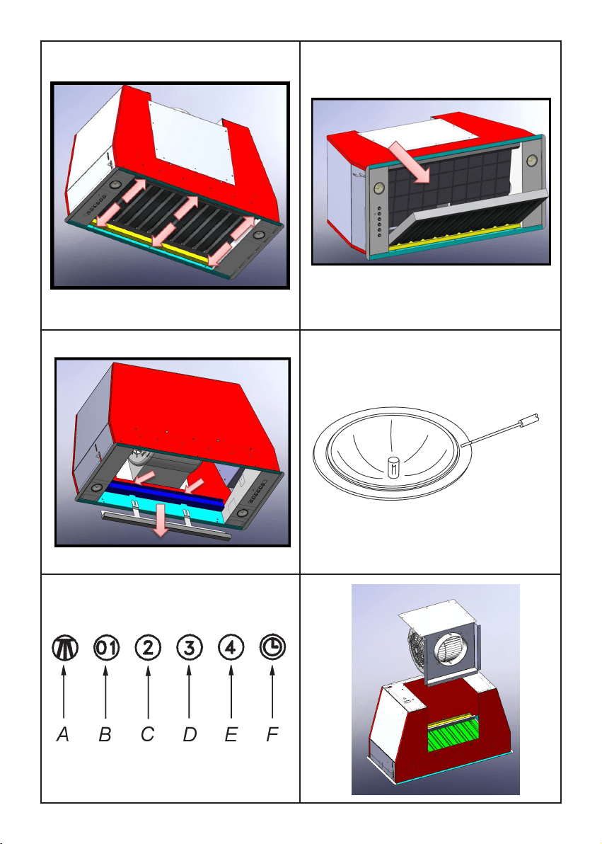
Insert the built-in unit in the hole made in
the cabinet until the stop click of the side-
springsisheardandthebuilt-inunitisblo-
cked.Insertthescrewsprovidedintheholes
inside the appliance (g.6) to block it com-
pletely.
Put the grease lter again
Blocking of the stop valve
Warning!
Beforeconnectingtheexibleexhausting
pipetothemotor,makesurethestopvalve,
which is on the air outlet ofthe motor, can
swing.
Exausting version
Connect the ange to the exhausting hole
with an appropriate pipe. Connect the ap-
pliancewiththeelectricalmainsthroughthe
supplycord.
Filtering version
Connect the ange with a pipe suitable to
conveytheairtothetopofthecabinet.Con-
nect the appliance with the electrical mains
throughthesupplycord.
Rear vented version
All the models with one motor can be rear
vented;ifthecustomerwantstousethisop-
tion,itisnecessarytoremovethe18screws
fromthemotorgroupsupport.Thentakethe
metal support with motor included out (pic.
11a). Turn the motor to have the air outlet
ontherearside(pic.11b)andxthescews
previouslyremoved.

7
MAINTENANCE
-Anaccuratemaintenanceguaranteesgood
functioningandlong-lastingperformance.
-Particularcareisduetothegreaselterpa-
nel.Itcanberemovedbypushingitsspecial
handle toward the back-side of the cooker
hoodandturningthelterdownwardssoto
unfastenitfromitsslot(Fig.3).
Toinsertthelterjustperformtheopposite
operation.
After 30 hours working, the push button
controlpanelwillsignalthesaturationofthe
greaselterbylightingallthebuttons.Press
thetimerbuttontoreset.
The grease lter needs cleaning by regular
hand-washing or in dishwashers every two
monthsatleastordependingonitsuse.
-Incasetheapplianceisusedinitsltering
version,theactivecoallter(Fig.7)needsto
be periodically replaced. The coal lter can
be removed by removing the grease lter
rst(Fig.3),andbypullingitsspecialplastic
tongue until it is unfastened from its slot.
Re-insert the coal lter by operating in the
oppositeway.
Thecoallterneedsreplacingdependingon
theuse,buthowevereverysixmonthsatle-
ast.
-Howtoremovetheoilcollector.Afterha-
vingremovedthegreaseltersandeventually
theactivecoallters,pleaseholdtheoiltank
upbyonehandandioosenthethreehandles
bytheotherhandasshoweding.8.Thenlet
thetankslidedownwardsmakingattentionin
ordertoavoidtheleakofoil.
Mod. S906-S907 (g. 10)
A:Lightswitchon/o
B:Motorswitchonspeed1/o
C:Motorswitchonspeed2
D:Motorswitchonspeed3
E:Motorswitchonspeed4
F:10-minutestimer
WORKING
INSTALLATION
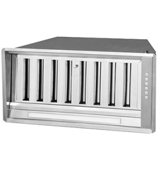
SL907
Before installing the appliance, make sure
thatnoneofthepartsisdamagedinanyway.
Incaseofdamagedparts,contactyourretai-
leranddonotproceedwithinstallation.
Read all of the following instructions with
carebeforeinstallingtheappliance.
-Useanairoutletpipeoftheshortestpos-
siblelength.
-Limitthenumberofpipebends.
-Useamaterialapprovedbystandardsand
regulations.
-Avoidanysuddenchangesinpipesection
(recommendedconstantdiameter:Ø150mm
/Ø200mmorequalsurfacearea).
Beforecarryingoutinstallation,pleaseremo-
vethegreaselterinordertoavoidpossible
damagestothe appliance. Please follow the
following steps to remove the metal grease
lter:openthelightedpanelrst,byturning
itdownwards(g.12),thenremovethegre-
aselterbyoperatingonitshandleandma-
kingthelterrotatedownwards,disengaging
itfromitsseat.
Makea hole on thesurfaceof the following
dimensions(dis.16):
270mmx498mmforSL907 52cmmodel
270mmx675mmforSL907 70cmmodel
InserttheSL907unit,makingsurethepush‐
buttonpanelisplacedontheright,looking
attheproductfromthefrontofthecook‐top.
Make the electric connection and connect
theair‐outletangetoasuitableexhausting
pipe.
Fixtheunitbyusingthefourscrewsprovided
andtightenthemasshowning.13.
Insert the grease lter again and close the
perimeterpanel.

8
-Tocleantheapplianceitselftepidwaterand
neutral detergent are recommended, whi-
le abrasive products should be avoided. For
steel appliances specialized detergents are
recommended(pleasefollowtheinstructions
indicated o the product itself to obtain the
desiredresults).
- Warning!Totakedowntheappliancefrom
the cabinet, remove the denitive xing
screws (g. 6) using a screw-driver, get o
thegreaselters(g.3)andtheactivecarbon
lters,iftheyareinserted(g.7).
Actonthesmallhandleofthesprings,which
are inside the built-in unit, with the neces-
sary strength to unhookthe appliance from
thecabinet.
* If the supply cordis damaged,it must be
replaced by the manufacturer or its sevice
agentorasimilarlyqualiedpersoninorder
toavoidahazard.
Replace the dichroic lamp SL906, remove
thelamp(g.9)byinsertingascrewdriveror
anothersharptoobetweenthelampandits
chromsupportandreplaceitwithal’appareil
lampofthesamekind.
Replace the led bar SL 906-L
Before to replace the led bar switch o the
appliancethenbyusingappropriatetoolsre-
movetheledbarfromitsslot(g.17).
Takeouttheledbarfromitsconnectorand
replacewithsimilarcharacteristics.
To nd the correct led bar please check on
thereplacementpartlist.
Replacement of SL 907 uorescent lamp
To replace the uorescent lamps of SL907
model,youneedtoopentheperimeter pa-
nel,byrotatingitasshowninFig.11,remove
thepanelxingscrews(g.13),payingspe-
cialcareinholding it during this step, then
removethe lamps andreplacethe damaged
one(g.14).
Insertthepanelagain.
If the supply cord is damaged, it must be
replaced by the manufacturer or its service
agentorasimilarlyqualiedpersoninorder
toavoidahazard.
9
10
11
12
13
14
15
16
1
2
3
SL906 600: 501 mm
SL906 850: 826 mm
SL906-L 850: 835 mm
SL906 1000: 985 mm
SL906 1200: 1100 mm
4
5
17
6
7
11a
10
8
9
18
13
14
15
16
11b 12
498 - 678
270
17
19
18

90001100906-GM03/14