Loading ...
Installation Guide
Beer Dispenser
866-319-5473
For assistance, please call:
2
8
Mount CO
2
Cylinder
Now place the CO cylinder on the
step and strap into place.
14
Position Keg
Carefully tilt beer keg and rest the edge on the keg floor
support on the bottom of the interior cabinet. Slide the keg in
slowly, ensuring that it is properly located, and all hoses are
clear of obstructions. Close door and enjoy.
5
Install Handle & Faucet
Screw the black faucet handle on to
the faucet. Then screw the faucet onto
the faucet adapter on the front of the
tower. Make sure the faucet is vertical,
with the black handle facing the
ceiling. The faucet should be screwed
on “hand tight.” Now place the plastic
drip pan beneath the faucet.
9
Connect Keg Coupler
To connect the keg coupler to the keg, first make sure the
black pull handle of the keg coupler is in the closed
(diagonal/upper) position. Insert the keg coupler into the
locking neck of the beer keg and turn clockwise 25° to lock in
into place. Now the keg coupler is secured to the keg.
11
Connect Beer Line
Now connect the beer line to the keg
coupler. Insert the neoprene washer
(provided with the kit) into the beer
line hex nut (the beer line is the line
coming from/going to the tower and
faucet). Remove the blue rubber
protective cap located on top of the
keg coupler and screw the nut with
the rubber washer to the top of the
keg coupler, hand-tighten firmly.
6
Connect Tube to Regulator
Make sure the CO
2
regulator shut off valve is
closed- the switch below the main body should be
perpendicular to the tubing. Install the 5 ft. CO
2
gas line tube to the regulator by attaching one end
of the tube into the hose barb connection on the
CO
2
regulator. Secure the tube by using one of the
two self-locking red plastic snap-on clamps. Use
pliers or clamp crimpers to snap the clamp on.
Then remove the black rubber plug from the back
of the unit and feed the remaining unused end of
the tubing through the hole.
7
Connect Regulator to Cylinder
Make sure the CO
2
cylinder is full and
closed. Then attach the CO
2
regulator to
the CO
2
cylinder by screwing the loose
golden regulator nut into the cylinder valve
and tightening with pliers. Note that a fiber
washer is normally required to connect a
regulator to a CO
2
cylinder, but the
standard regulator provided includes a
built-in o-ring.
12
Tap Keg
To secure the tank connection,
pull the tap handle out (away
from the keg coupler) and
push down until it locks into
position. Listen for the “click”
of the pull handle when it
shifts into the final downward
position. The keg is now
tapped.
10
Attach Tube to Coupler
Now attach the remaining open end of the CO
2
gas line tube to
the keg coupler’s hose barb. Then secure the tube by using the
remaining self-locking red plastic snap-on clamp. Use pliers or
clamp crimpers to snap the clamp securely.
13
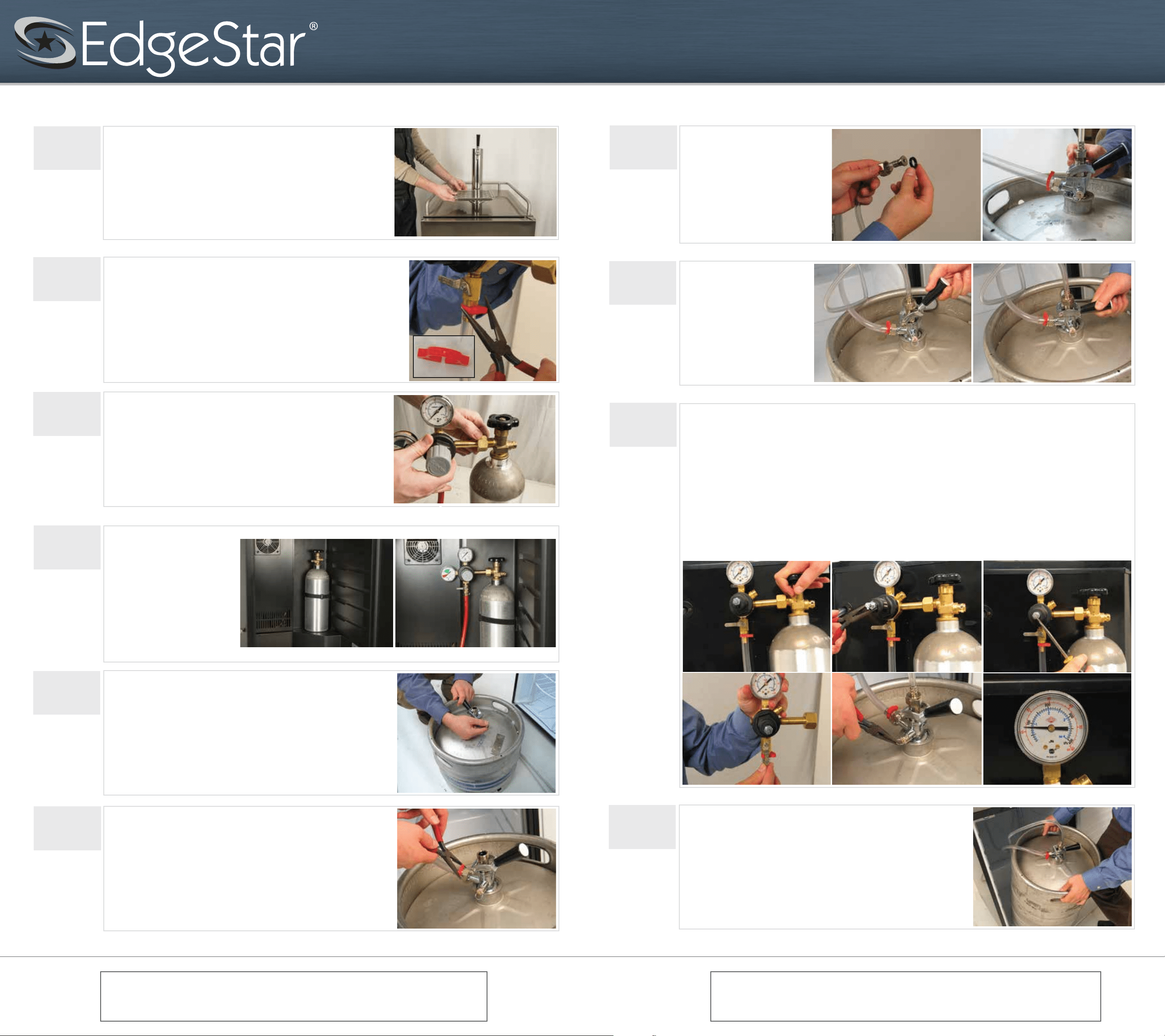
Calibrate Regulator
(A) With the shut-off valve on the regulator closed, open the valve on the gas cylinder completely. (B) With a pair of
pliers, loosen adjustment nut allowing adjustment screw to be turned counter-clockwise until adjustment screw is
completely open. (C) Now slowly turn the regulator adjustment screw until the desired pressure is shown on the output
pressure gauge. Under normal circumstances, we recommend setting the regulator at 12psi. NOTE: Other conditions,
such as altitude or special beer type, may require some adjustment. On regulators designed for draft beer, turning
clockwise will increase the output pressure, and turning counter-clockwise will decrease the output pressure. (D) Open
the shut-off valve on the regulator-the switch below the main body should be parallel to the tubing. Gas should now flow
from the regulator to the keg coupler. You will hear the keg pressurizing. The output needle will drop momentarily until
the pressure has equalized. Then the needle will return to the point you set it at. (E) The keg coupler is designed with a
pressure relief valve (PRV). Pull the ring on the PRV briefly to allow gas to vent. This will permit gas to flow through the
regulator and help obtain a more accurate reading on the output pressure gauge. (F) Re-check the output pressure on
the regulator, and if necessary re-adjust using step B until the desired pressure is shown.
NOTE: It is always wise to follow up any adjustment to the regulator with a brief pull of the PRV ring to ensure an
accurate output reading.
A B C
D E F
Warning
CO
2
can be dangerous! CO
2
cylinders contain high-pressured gas, which can be
hazardous if handled improperly. Please handle with care.
Note: This manual is intended as a guide for installation. While there are many
different ways to install this kit, we recommend you follow these instructions. If you
are uncomfortable in your ability to assemble this kit, seek professional assistance.
055 061
2