Loading ...
2
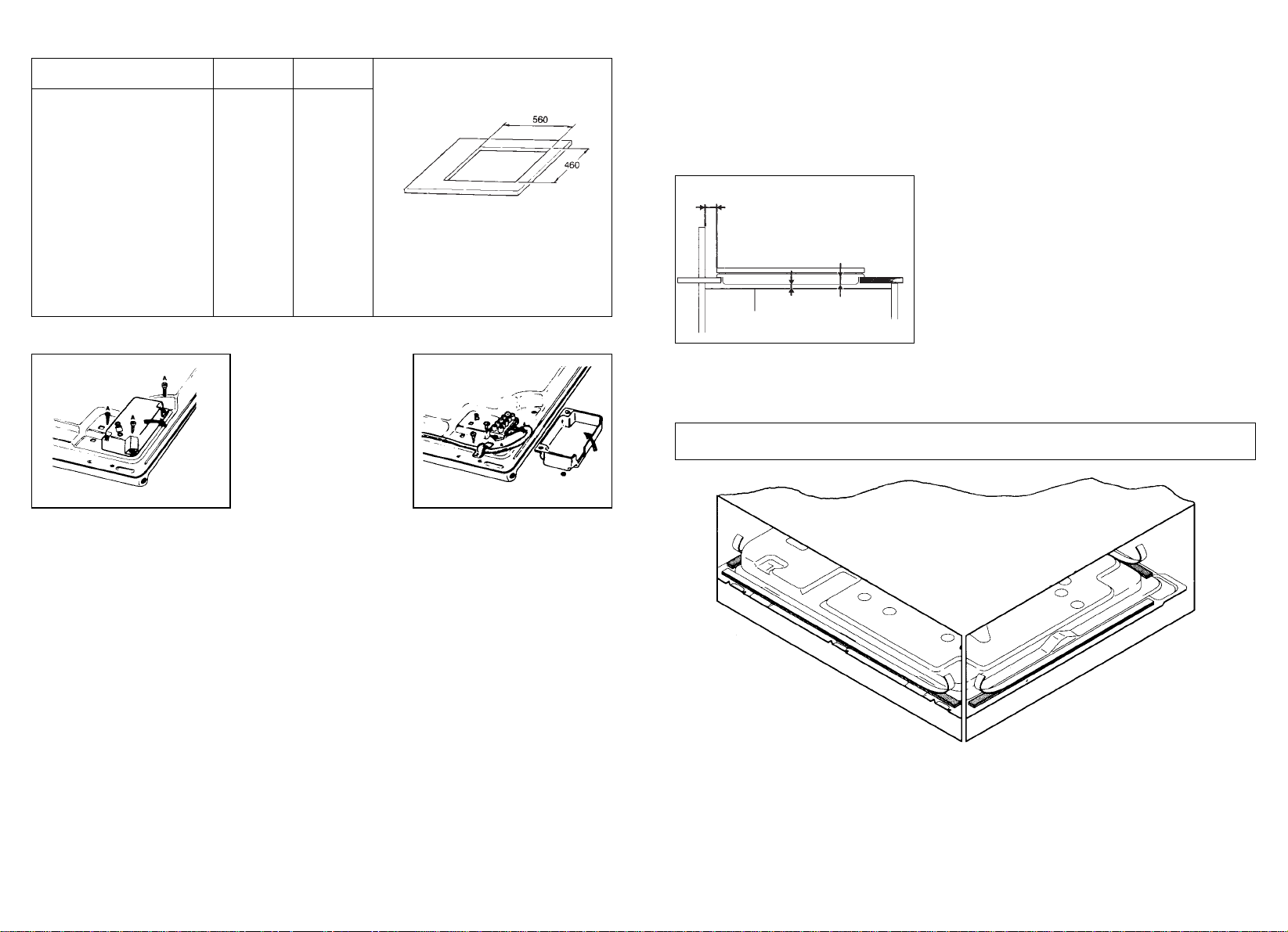
VERY IMPORTANT - APPLYING THE SEALANT
Important - The diagram below shows how the sealant should be applied.
INSTALLATION
The Purchaser is responsible for the installation of the hob. The Manufacturer does not
accept any responsibility for any damage or loss resulting from incorrect installation,
and as such this will not covered by the Manufacturer’s Guarantee.
The hob may be installed in any worktop which is heat resistant to a temperature of
100° C, and has a thickness of 25 - 40 mm. The dimensions of the insert to be cut
out of the worktop are in shown in Fig. 1.
If the Hob is fitted next to a cabinet on either side,
the distance between the Hob and the cabinet
must be at least 150 mm (see Fig. 2); while the
distance between the hob and the rear wall must
be at least 55 mm.
If no other appliance is fitted below Hob, there
must be a partition panel in insulating material
(wood or similar) providing a space of at least 10
mm below the Hob (see Fig. 2).
The Hob unit is fitted by attaching the Fixing
Clamps supplied, using the holes at the base of
the unit.
TECHNICAL CHARACTERISTICS
Cooking hobs 60x50
Gas
Electric
Burners 4 gas –
– 4 elec.
Reference type P4 01 PE 03
Supply Voltage/Frequency (V/Hz) 220-240/50 *
Installed electric power (W) – 6300
Gas burner power:
Small burner kW 1,45 (x 3) –
Large burner kW 2,9 –
Power of gas installed:
- G20/20 mbar (kW) 7,45
- G30/28-30 mbar (g/h) 542
Electric ignition yes –
Product size mm. 585x500 585x500
Degree protection – Type Y
Class 3
Reference on electrical diagram
(page 10) 1
Fig. 1
Fig. 2
Partition panel
30 mm
min.
30 mm
10 mm
Fig. 4 Fig. 4 bis
* 220-240V~/380-415V3N~
This appliance has been designed for non-professional, i.e. domestic, use.
Loading ...
Loading ...
Loading ...