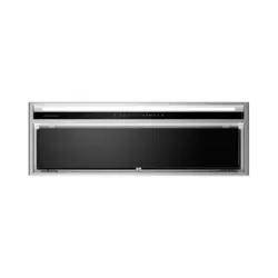

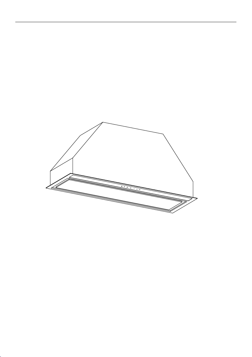
BUILT-IN INTEGRATED
COOKER HOOD
HP90IHCB3 & HP60IHCB3 models
INSTALLATION GUIDE / USER GUIDE
GB IE


1
IMPORTANT!
SAVE THESE INSTRUCTIONS
The models shown in this user guide
may not be available in all markets
and are subject to change at any time.
For current details about model and
specification availability in your country,
go to our website fisherpaykel.com or
contact your local Fisher & Paykel dealer.
Registration
Register your product with us so we can
provide you with the best service possible.
To register your product visit our website:
fisherpaykel.com
Introduction 3
Safety and warnings 4
Installation Instructions 7
About your cooker hood – Energy efficiency 15
Operating instructions 16
Cleaning and maintenance 17
Parts and accessories 18
Manufacturer’s Warranty 19
Customer Care 20
CONTENTS

3
Thank you for purchasing a Fisher & Paykel product.
Thousands of hours go into the design, engineering, testing and perfecting of each
Fisher & Paykel appliance. The care and attention given to creating these beautiful
products doesn’t stop once it has found its home with you.
This use and care manual will answer most of your questions about the set-up, use
and on-going maintenance of your Fisher & Paykel product; however if you require
further information about your product and its use please consult our website for
solutions and further contact information to discuss with a service representative.
To ensure you receive all relevant product updates and the best service possible,
please register your Fisher & Paykel products through our website.
INTRODUCTION

4
SAFETY AND WARNINGS
!
WARNING!
10kg
(HP60)
11.5kg
(HP90)
Weight Hazard
The cooker hood is heavy. Please ensure
adequate care is taken when installing the
cooker hood to prevent personal injury.
Thecooker hood must be installed onto a
solid wall, stud, beam or truss. Weight of the
product is 10kg (HP60) / 11.5kg (HP90)
!
WARNING!
Electric Shock Hazard
Always disconnect the appliance from the
mains power supply before carrying out any
maintenance or repairs. Alterations to the
domestic wiring system must only be made
by a qualified electrician. Failure to follow this
advice may result in electrical shock or death.
IMPORTANT SAFETY INSTRUCTIONS
WARNING!
When using this appliance always exercise basic
safety precautions including the following:
• Please read the entire set of instructions before
installing the cooker hood.
• This appliance can be used by children aged
from 8years or above and persons with reduced
physical, sensory or metal capabilities or lack of
experience or knowledge if they have been given
supervision or instruction concerning use of the

5
SAFETY AND WARNINGS
appliance in a safe way and understand the hazards
involved. Childrenshall not play with the appliance.
Cleaningand user maintenance shall not be made
bychildren without supervision.
• The installation of Fisher & Paykel cooker hoods
must comply with the information in this guide.
Failure to install the cooker hood in accordance
withthese installation instructions may result in
electrical hazards, injury, and damage to your
appliance and loss of warranty. Failure by the
installer to install the screws or fixing devices in
accordance with these installation instructions
may result in electrical hazards. Please install the
appliance as detailed in these instructions.
• There shall be adequate ventilation of the room
when the cooker hood is used at the same time
asappliances burning gas or other fuels.
• You must read the details concerning the method
and frequency of cleaning.
• There is a fire risk if cleaning is not carried out
inaccordance with the instructions.
• Do not flambé under the cooker hood.
• Exhaust air must not be discharged into an existing
flue that is used for exhausting fumes from appliances
burning gas or otherfuels.
• The minimum distance between the supporting
surface for cooking vessels on the hob and the
lowest part of the cooker hood shall be 600mm,
or 650mm if installed over a gas hob.
• Attention should be given to ensure that any
applicable regulations concerning the discharge
ofexhaust air is fulfilled.

6
• If the supply cord of this equipment is damaged
it must only be replaced by the manufacturer,
itsservice agent or similarly qualified person
inorder toavoid a hazard.
• Always switch the power off prior to installation,
servicing or cleaning the cooker hood.
• Never use the cooker hood without the filters
inplace.
• Stainless steel or powdercoat is very easily damaged
during installation if abraded or knocked by tools.
It is recommended to protect the top of the cooker
hood with cardboard or plastic bag during the
installation to minimise the risk of damage occurring.
• To reduce the risk of damage occurring to hob,
it is recommended that the surface of the hob
isprotected with cardboard or a similar object
during installation of the cooker hood.
• A power outlet should be within 750mm of the
motor assembly and can be either on the wall,
behind the chimney or in the ceiling.
• To comply with electrical safety regulations, this
cooker hood must be plugged into a socket near
theappliance. The socket must be accessible, or
have an accessible isolating switch, to enable the
end user to isolate the cooker hood from the power
for the purpose of internal cleaning or maintenance.
• Ducting accessories are not supplied.
Allductingmust comply with local requirements
andbuilding codes.
• CAUTION: accessible parts may become hot
whenused with cooking appliances.
SAFETY AND WARNINGS
7
INSTALLATION INSTRUCTIONS
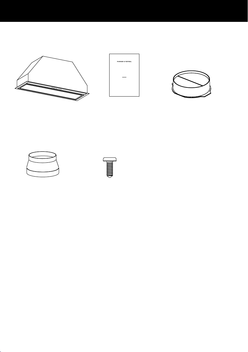
Contents of packaging
13mm screw
(2)
Installation instructions
User guide manual
(1)
125mm ducting
adapter (1)
Cooker hood
(1)
BUILT-IN INTEGRATED
COOKER HOOD
HP90IHCB3 & HP60IHCB3 models
INSTALLATION GUIDE / USER GUIDE
GB IE
150mm ducting adapter
with non return flap
(1)
8
INSTALLATION INSTRUCTIONS
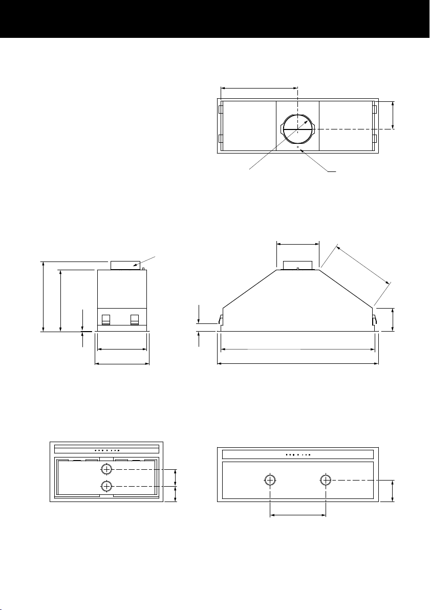
Product and cabinetry cutout dimensions
J
K
Power cord location
Ø
L
H
I
G
E
B
O
F
C
A
D
(
A)
Ducting adapter
M
N
M
N
HP60 HP90

9
INSTALLATION INSTRUCTIONS
HP60 HP90
PRODUCT DIMENSIONS mm
A
Overall height of product
(with ducting adapter)
350
(395)
315
(360)
B
Overall width of product 530 830
C
Overall depth of product 280 280
D
Thickness of flange 2 2
E
Width of chassis 492 792
F
Depth of chassis 255 255
G
Height of side of chassis 120 120
H
Width of top surface of chassis 220 220
I
Length of angled surface of chassis 260 335
J
Distance from centre of ducting outlet
to back of chassis
145 145
K
Distance from centre of ducting outlet
to side of chassis
245 395
L
Diameter of ducting outlet 150 150
M
Distance between centre of lights 80 285
N
Distance from centre of light to back of product 70 115
Length of power cord 750 750
CABINETRY CUTOUT DIMENSIONS
Overall width of cutout 500 800
Overall depth of cutout 260 260
O
Base of brackets/clips to bottom of chassis min. 15 – max. 40 min. 15 – max. 40
IMPORTANT!
Actual product dimensions may vary by ± 2mm.
Please read the entire instructions before installing the cooker hood.
10
INSTALLATION INSTRUCTIONS
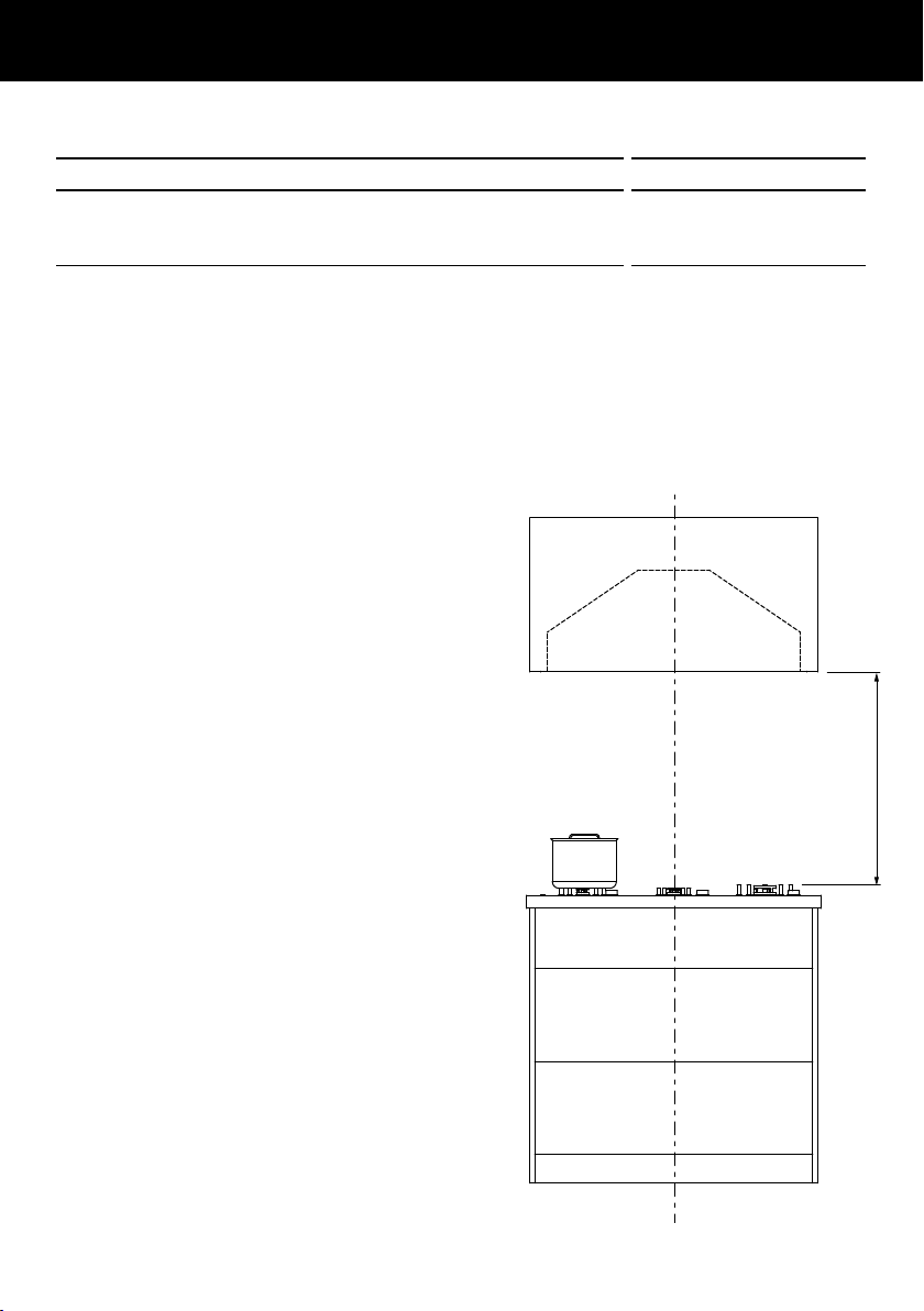
Height of cooker hood
MINIMUM CLEARANCES mm
P
Height top of hob to base of product
* Electric hob (for induction hob see note below)
Gas hob
min. 600 – max. 750
min. 650 – max. 750
Cooker hood installation height above the hob is the user’s preference. This cooker
hood must be installed between the minimum and maximum height limits indicated
inthe table above. Installation at the minimum height limit will improve the efficiency
ofcapturing cooking odours, grease and smoke. Installation at the maximum height limit
improves user ergonomics by offering increased head room.
* Induction cooking considerations
Induction hobs use energy efficient
technology that only heats the contents
ofa cooking pot.
Unlike gas or traditional electric hobs,
thesurrounding air does not get heated
when using an induction hob. As a
result, cooker hood filters, splashbacks
and surrounding cabinetry do not get
warmed up, increasing the likelihood of
condensation on these cooler surfaces.
Other factors like ambient temperature,
humidity, natural ventilation of the
room, size of the cookware and how the
induction hob is being used also influence
condensation. For example, aggressive
boiling on high hob heat settings like
PowerBoost increases the rate at which
water is evaporated, increasing the
likelihood of condensation.
It is important to understand that neither
the cooker hood nor the induction hob
arefaulty as a result of this phenomenon.
Condensation can be minimised by:
Installing the cooker hood at the maximum
height above the hob as specified in this
user guide.
Using the cooker hood on a lower speed
setting when boiling.
Using the induction hob on a lower heat
setting when boiling.
Switching the cooker hood on 5minutes
before cooking and letting it run for atleast
5minutes after cooking.
Refer to the ‘Operating instructions’ section
on how to use the timer function.
P
11
Venting requirements
IMPORTANT!
To reduce risk of fire and to properly exhaust air, be sure to duct air outside —
Donotvent exhaust air into spaces within walls or ceilings or into attics,
crawl spaces, or garages.
The range hood can be installed to operate with the exhaust air ducted externally
fromthekitchen or with the exhaust air recirculating within the kitchen.
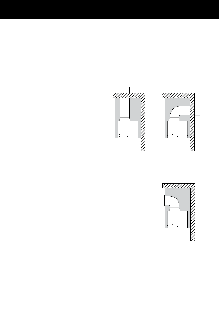
External venting
For best results:
Use the shortest and straightest duct
route possible. Elbowsandtransitions
increase noise and reduce air flow
efficiency.
Use rigid or semi-rigid ducting 150mm
diameter with a 160mm (minimum)
round hole inthe wall or ceiling.
Note: In difficult installations where
flexible ducting is required ensure
thatit is pulledtight.
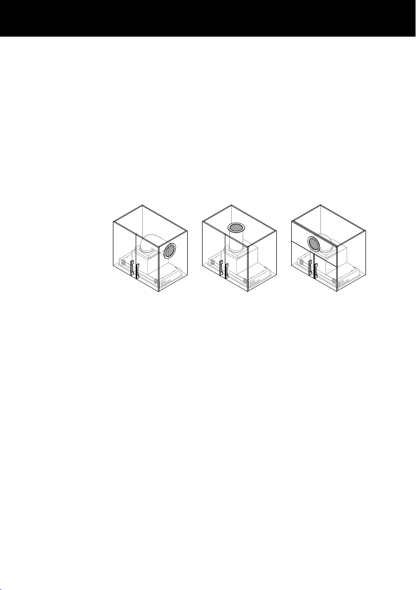
Recirculating
This range hood can be installed to recirculate within
thekitchenwhere ducting externally is not practical.
Thecarbon filters fit on the blowers within the cavity of the
range hood and absorb odours as they pass over the filters.
The exhaust air then passes through the blower unit and
the diverter before recirculating back into the kitchen from
the side vents at the top ofthechimney.
Note: A ducting hole is not required in the wall or ceiling
when installing a range hood to berecirculated.
To operate this range hood with the air recirculating the
followingis required:
Carbon filters (refer to ‘Parts and Accessories’).
150mm ducting. The ducting diameter must match
thediameterorthe blower outlet.
150mm louvered vent.
INSTALLATION INSTRUCTIONS
Recirculate with carbon filters
Vent through roof Vent through exterior wall
12
INSTALLATION INSTRUCTIONS
Installation
WARNING!
This product is heavy and requires two persons for installation.
WARNING!
Failure to install the screws or fixing device in accordance with these instructions
mayresult in electrical hazards.
The manufacturer is not liable for any damage caused by not following these instructions.
1
Prepare for installation.
Before installing your cooker hood:
Please read the instructions carefully.
Unpack the cooker hood and check that all functions are working.
Ensure that the voltage (V) and the frequency (Hz) indicated on the serial plate
match the voltage and frequency at the installation site.
The stainless steel and glass surfaces of the cooker hood are very easilydamaged
during installation if grazed or knocked by tools. Take care to protect the surfaces
during installation.
Protect the hob surface below with cardboard, or the like, toprevent damage
occurring whilst the cooker hood isbeinginstalled above.
2
Fit the 150mm ducting adapter with non return flap tothecooker hood using the
screwssupplied.
3
Provide an opening on the underside of the cupboard (seeproduct and cabinetry
cutout dimensions).
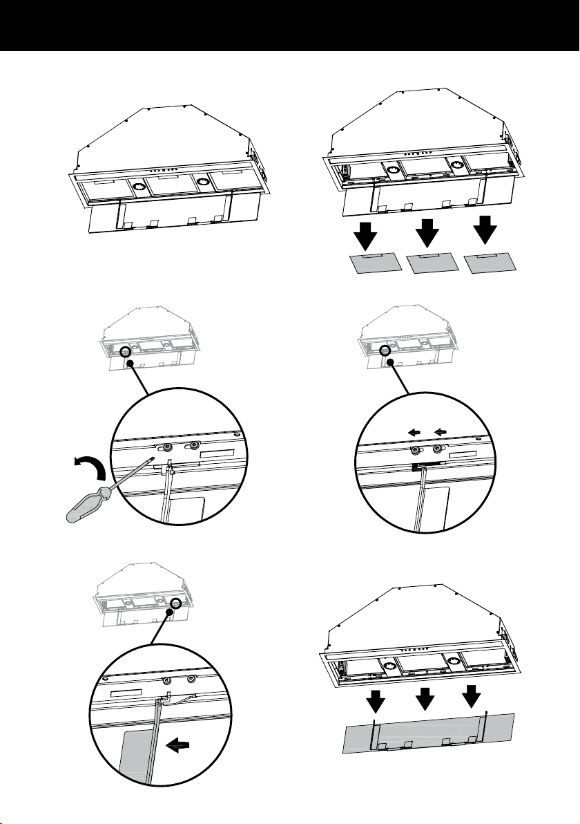
4
Remove the filters and face plate of the cooker hood.
IMPORTANT!
Venting directly into the cabinet with no ducting and louvered vent is not permitted.
To recirculate your perimeter insert range hood:
1
Determine the desired location of the 150mm louvered vent on your cabinetry.
Thelouvered vent can be placed on the side or front of your cabinet provided there
issufficient clearance from the surrounding cabinetry to enable ventilated air to
recirculate back into your kitchen.
Note: Placement of the louvered vent on the top of your cabinetry is not recommended.
This should only be done if objects can be prevented from falling through the louvers
into the blower.
2
Create a cutout in your cabinet to fit the 150mm louvered vent. Place the louvered vent
on the hole created and secure (A).
3
Connect the blower outlet to the louvered vent with a length of 150mm rigid ducting,
and secure the joints with aluminum tape. Ensure there is no slack in the ducting.
Recirculation
venting options
A
Side To p
Front
13
INSTALLATION INSTRUCTIONS
A B
C
360˚
1
A B
C
360˚
2
A
B
C
360˚
A
B
C
360˚
A B
C
360˚
A B
C
360˚
3 4
5
6
14
INSTALLATION INSTRUCTIONS
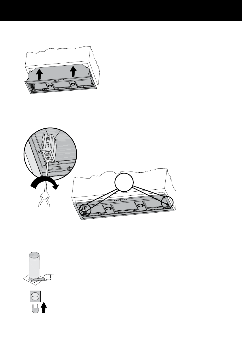
5
Lift the cooker hood and fit through the opening of the cupboard
till the spring loaded brackets / clips hold the product in place.
width
depth
2.3
2.2
2.1
x4
6
Secure cooker hood while tightening the 4 brackets / clips.
width
depth
2.3
2.2
2.1
x4
7
Connect duct and plug cooker hood in.
width
depth
2.3
2.2
2.1
x4

15
Product Fiche
EN61591
MODEL
HP60IHCB3
HP90IHCB3
Annual Energy Consumption (kWh/annum) 32.2
Time Increase Factor 1
Energy Efficiency Index 52.8
Energy Efficiency Class A
Fluid Dynamic Efficiency 28.5
Fluid Dynamic Efficiency Class A
Lighting Efficiency 16.1
Lighting Efficiency Class C
Grease Filtering Efficiency 91.2
Grease Filtering Efficiency Class B
Airflow at Min. Speed (m³/hr) 200
Airflow at Max. Speed (m³/hr) 525
Airflow at Boost Speed (m³/hr) 710
Airborne noise at minimum (dB) 40
Airborne noise at maximum (dB) 64
Airborne noise at Boost (dB) 67
Airflow At Best Efficiency Point (m³/hr) 348.4
Electrical Power Input At Best Efficiency Point (W) 76.1
Lighting Nominal Power (W) 7
Lighting Average Illumination (lux) 113
Power consumption in Off mode (W) 0.41
Power consumption in Standby mode (W) 0.41
ABOUT YOUR COOKER HOOD – ENERGY EFFICIENCY
16
OPERATING INSTRUCTIONS
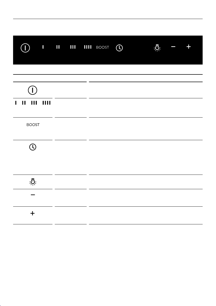
Touch control panel
CONTROL PANEL FEATURES
Power on/off Turn the cooker hood on or off.
The fan automatically turns on to operate at level 1.
Fan speed
1 – 4
Adjust the fan speed levels from 1 – 4 with 1 being the
lowest level and 4 being the highest.
The fan speed level icon illuminates red when selected.
Boost Turn the fan onto boost speed.
The icon flashes red when it is on.
The cooker hood will operate on boost speed for
5minutes and will then revert to speed 4.
Timer Turn the timer on.
The fan operates for 5minutes at the current speed
and each descending speed before turning off.
The timer icon flashes red when the filters need cleaning.
To reset the timer press the button and it will stop
flashing and begin counting again.
Lights on/off Turn the lights on or off.
The lights turn on to the last level selected.
Reduce
lighting level
Press once to adjust the light to the lowest level.
The icon illuminates red when on the lowest level.
Press and hold to progressively dim the light level.
Increase
lighting level
Press once to adjust the light to the highest level.
The icon illuminates red when on the highest level.
Press and hold to progressively increase the light level.

17
CLEANING AND MAINTENANCE
IMPORTANT!
Never use abrasive or oil based cleaners
General maintenance
Before performing any cleaning or maintenance on your cooker hood, ensure that
thepower supply is switched off to the hood.
The cooker hood should be cleaned regularly using a mild, liquid detergent to avoid
abuild up of grease occurring. Grease deposits are corrosive which can cause damage
to your cooker hood.
Note: in areas of high humidity or coastal environments, cleaning should be carried out
more frequently.
Aluminium filters
Depending on use, and at least once a month, the
aluminium grease filters should be removed and cleaned
with hot soapy water or in a dishwasher.
If washed in a dishwasher, the filters should be placed in
an upright position to prevent food from falling on them.
After rinsing and drying, replace the filters.
Note: some discolouration of the frames may occur.
Removing the aluminium filters:
1
Open the glass panel.
2
Pull the relative filter catch, tilting it downwards until it disengages from the supports.
3
Reverse these instructions when refitting the filters.
Carbon filters – for use in recirculation mode
Active carbon filters are disposable items designed to remove grease and odours from
cooking vapours before the air is channelled back into the kitchen. The active carbon
filters must be replaced periodically to work properly, at least once every three months,
depending on the frequency with which the cooker hood is used.
Note: fully saturated carbon filters can become a
barrier to air movement therefore limiting cooker
hood performance. In the event of fire, grease laden
filters could be flammable and therefore regular
replacement is recommended.
Light bulb replacement
Note: replacement bulbs are not covered bywarranty.
1
Open the glass panel.
2
Remove the aluminium filters.
3
Unscrew the light bulb.
4
Insert the replacement bulb into the lamp socket.
5
Replace the aluminium filters.
6
Replace the glass panel.
Bulb replacement
A B
C
360˚

18
PARTS AND ACCESSORIES
ITEM REFERENCE NUMBER
LED bulb x2 792556
Aluminium filter 792429
Recirculation carbon filter x2 792481

19
MANUFACTURER’S WARRANTY
You automatically receive a 2 year Manufacturer’s Warranty with the purchase ofthis
Built-in integrated cooker hoodcovering parts and labour for servicing within the
UnitedKingdom and Ireland.
Fisher & Paykel undertakes to:
Repair or, at its option, replace without cost to the owner either for material or labour
any part of the product, the serial number of which appears on the product, which is
found to be defective within TWO YEARS of the date of purchase.
Note: this Manufacturer’s Warranty is an extra benefit and does not affect your legalrights.
This Manufacturer’s Warranty DOES NOT cover
A
Service calls which are not related to any defect in the product. The cost of a service
call will be charged if the problem is not found to be a product fault. For example:
1
Correcting the installation of the product.
2
Instructing you how to use the product.
3
Replacing house fuses or correcting house wiring or plumbing.
4
Correcting fault(s) caused by the user.
5
Noise or vibration that is considered normal, eg drain/fan sounds, refrigeration
noises oruserwarning beeps.
6
Correcting damage caused by pests, eg rats, cockroaches, etc.
7
Replacement light bulbs.
B
Defects caused by factors other than:
1
Normal domestic use; or
2
Use in accordance with the product’s user guide.
C
Defects to the product caused by accident, neglect, misuse or ‘act of God’.
D
The cost of repairs carried out other than by a Fisher & Paykel trained and supported
service technician or the cost of correcting such repairs.
E
Normal recommended maintenance as set out in the product’s user guide.
F
Repairs when the appliance has been dismantled, repaired or serviced by other than
aFisher & Paykel trained and supported service technician or the selling dealer.
G
Pick-up and delivery.
H
Transportation or travelling costs involved in the repair when the product is installed outside
the Fisher & Paykel trained and supported service technician’s normal service area.
Nothing in this Manufacturer’s Warranty is intended to, or does limit, any rights you may
have under law to recover the costs of inspecting or returning the goods to us.
This product has been designed for use in a normal domestic (residential) environment.
This product is not designed for any commercial use (whatsoever). Any commercial use
by acustomer will affect this product’s Manufacturer’s Warranty.
Service under this Manufacturer’s Warranty must be provided by a Fisher & Paykel
trained and supported service technician (refer to the ‘Customer Care’ section at
the back of this book). Suchservice shall be provided during normal business hours.
ThisManufacturer’s Warranty certificate should be shown when making any claim.
Please keep this user guide in a safe place.

20
CUSTOMER CARE
Before you call for service or assistance...
Check the things you can do yourself. Refer to your user guide and check that:
1
Your product is correctly installed.
2
You are familiar with its normal operation.
If after checking these points you still need assistance or parts, please refer to your
nearest Fisher & Paykel trained and supported service technician, Customer Care, or
contact us through our website fisherpaykel.com.
In the United Kingdom if you need assistance…*
Call the Fisher & Paykel Customer Care Centre and talk to one of our
CustomerCareConsultants.
Phone: 08000 886 605
Fax: 08000 886 606
Website: fisherpaykel.com
Postal address: Fisher & Paykel Appliances Ltd, Maidstone Road, Kingston,
MiltonKeynes, Buckinghamshire, MK10 0BD
In Ireland if you need assistance…*
Call the Fisher & Paykel Customer Care Centre and talk to one of our
CustomerCareConsultants.
Phone: 1800 625 174 or 01-8077960
Fax: 1800 635 012
Website: fisherpaykel.com
Postal address: Fisher & Paykel Appliances, Unit D2,
North Dublin Corporate Park, Swords, Co. Dublin
*If you call, write or contact us via our website please provide:
your name and address, model number, serial number,
date of purchase and a complete description of the problem.
This information is needed in order to better respond to your request for assistance.
Product details can be found on the inside of the chassis.
The filter needs to be removed to be able to see them.
Registration
Register your product with us so we can provide you with the best service possible.
To register your product visit our website: fisherpaykel.com

21
CUSTOMER CARE
Complete and keep for safe reference:
Model
Serial No.
Purchase Date
Purchaser
Dealer
Suburb
Town
Country

GB IE
104040D 08.18
FISHERPAYKEL.COM
© Fisher & Paykel Appliances 2018. All rights reserved.
The product specifications in this booklet apply to the specific products
and models described at the date of issue. Under our policy of continuous
product improvement, these specifications may change at any time. You
should therefore check with your Dealer to ensure this booklet correctly
describes the product currently available.