
Loading ...
2
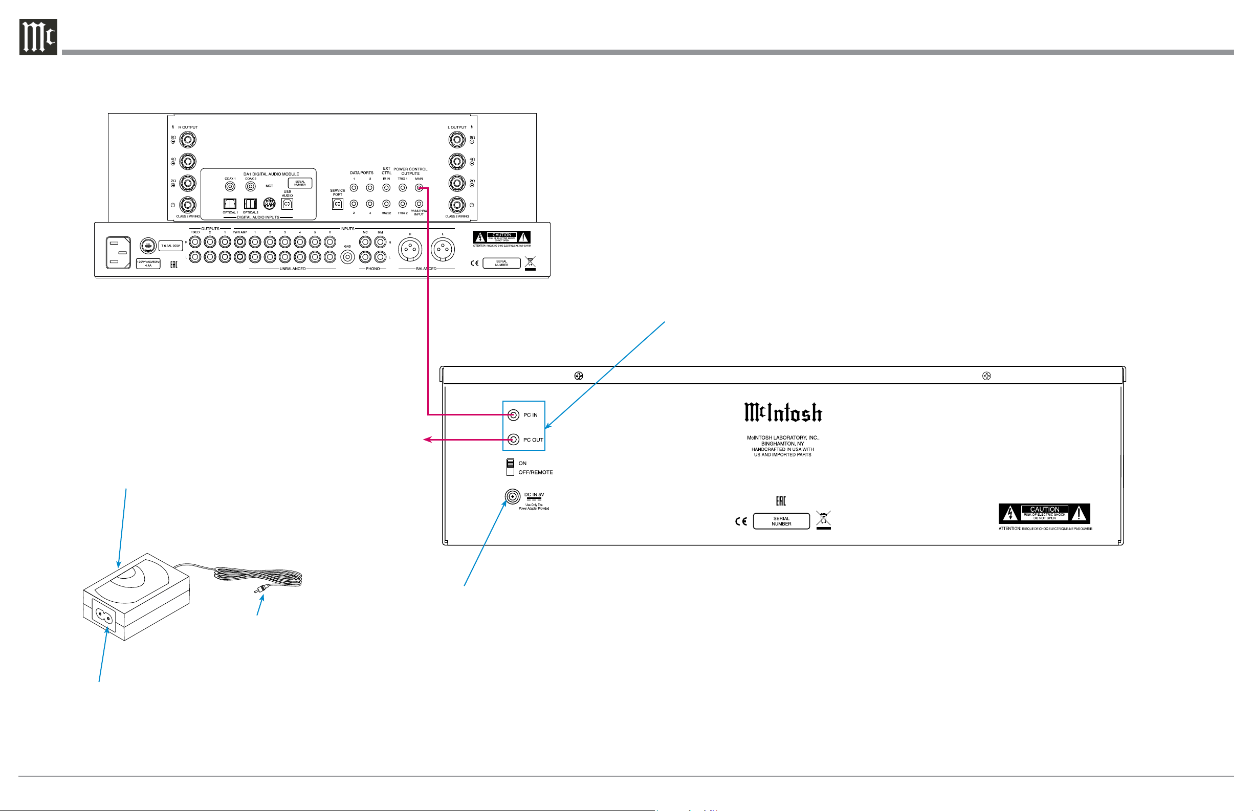
Connection Diagram and Operation
LB100 LIGHT BOX
PC IN (Power Control/Trigger) receives turn-
on signals from a McIntosh component and PC
OUT (Power Control/Trigger) sends turn-on
signals on to another McIntosh Component
Connect the supplied
AC/DC Power Adapter
DC Output Connnector
The AC/DC Power Adapter supplied
with the LB100 McIntosh Light Box
Connect to a live AC outlet (always On)
using the supplied AC Power Cord. Re-
fer to information on the power supply
to determine the correct voltage
Connect to the DC IN 5V
connector on the Rear Panel
of the LB100 McIntosh Light
Box
Integrated Amplifier or Preamplifier
Connect to another McIntosh
Component Power Control or
Trigger Input Jack
Power On
Place the ON-OFF/REMOTE Power Control Switch in the ON
position or, if the PC IN Jack is connected to the Power Control/
Trigger Jack from a McIntosh Component, place the switch in
the OFF/REMOTE position.
Power Off
Place the ON-OFF/REMOTE Power Control Switch in the
OFF/REMOTE position or, if the PC IN Jack is connected to
the Power Control/Trigger Jack from a McIntosh Component,
switch power Off on the connected McIntosh Component.