
Please read this manual carefully before operating the TV.
Retain it for future reference.
Record model number and serial number of the set.
See the label attached to the TV back cover and quote this
information to your dealer when you require service.
table of contents page 5
setup checklist page 7
Internet Home Page : http://www.lgcommercial.com
P/N : 3828VA0524D (DCL-34)
© Copyright 2007, LG Electronics U.S.A., Inc.
Installation and Operating Guide Warranty
Model Number DU-27FB34C
master TV setup | page 8
Page 2
WARNING: TO REDUCE THE RISK OF ELECTRIC SHOCK DO NOT REMOVE COVER (OR BACK). NO USER
SERVICEABLE PARTS INSIDE. REFER TO QUALIFIED SERVICE PERSONNEL
The lightning flash with arrowhead symbol, within an equilateral triangle, is intended to alert
the user to the presence of uninsulated “dangerous voltage” within the product’s enclosure
that may be of sufficient magnitude to constitute a risk of electric shock to persons.
The exclamation point within an equilateral triangle is intended to alert the user to the pres-
ence of important operating and maintenance (servicing) instructions in the literature accom-
panying the appliance
WARNING:
TO PREVENT FIRE OR SHOCK HAZARDS, DO NOT EXPOSE THIS PRODUCT TO RAIN OR MOISTURE.
POWER CORD POLARIZATION:
CAUTION: To prevent electric shock, match wide blade of plug to wide slot, fully insert.
ATTENTION: Pour éviter les chocs électriques, introduire la lame la plus large de la fiche dans la borne
correspondante de la prise et pousser jusqu’au fond.
NOTE TO CABLE/TV INSTALLER:
This reminder is provided to call the cable TV system installer’s attention to Article 820-40 of the National
Electric Code (U.S.A.). The code provides guidelines for proper grounding and, in particular, specifies that the
cable ground shall be connected to the grounding system of the building, as close to the point of the cable
entry as practical.
REGULATORY INFORMATION:
This equipment has been tested and found to comply with the limits for a Class B digital device, pursuant to
Part 15 of the FCC Rules. These limits are designed to provide reasonable protection against harmful interfer-
ence when the equipment is operated in a residential installation. This equipment generates, uses and can
radiate radio frequency energy and, if not installed and used in accordance with the instruction manual, may
cause harmful interference to radio communications. However, there is no guarantee that interference will not
occur in a particular installation. If this equipment does cause harmful interference to radio or television
reception, which can be determined by turning the equipment off and on, the user is encouraged to try to
correct the interference by one or more of the following measures:
• Reorient or relocate the receiving antenna.
• Increase the separation between the equipment and receiver.
• Connect the equipment into an outlet on a circuit different from that to which the receiver is connected.
• Consult the dealer or an experienced radio/TV technician for help.
CAUTION:
Do not attempt to modify this product in any way without written authorization from LG Electronics
U.S.A., Inc. Unauthorized modification could void the user’s authority to operate this product.
COMPLIANCE:
The responsible party for this product’s compliance is:
LG Electronics U.S.A., Inc.
1000 Sylvan Avenue, Englewood Cliffs, NJ 07632, USA • Phone: 1-201-816-2000.
WARNING
RISK OF ELECTRIC SHOCK
DO NOT OPEN
For Customer Support/Service, please call:
1-888-865-3026
www.lgcommercial.com
Marketed and Distributed in the United States by LG Electronics U.S.A., Inc.
2000 Millbrook Drive, Lincolnshire, IL 60069
© Copyright 2007, LG Electronics U.S.A., Inc.
RECORD THE SERIAL NUMBER
The serial number of this Color TV is located on
the back of the cabinet. For future reference, we
suggest that you record the serial number here:
MODEL NO. DU-27FB34C
SERIAL NO.____________________________

Page 3
• Read these instructions.
• Keep these instructions.
• Heed all warnings.
• Follow all instructions.
1. Do not use this apparatus near
water.
2. Clean only with a dry cloth.
3. Do not block any ventilation open-
ings. Install in accordance with the
manufacturer’s instructions.
4. Do not install near any heat sources
such as radiators, heat registers,
stoves, or other apparatus (including
amplifiers) that produce heat.
5. Do not defeat the safety purpose of
the polarized or grounding-type
plug. A polarized plug has two
blades with one wider than the
other. A grounding-type plug has
two blades and a third grounding
prong. The wide blade or the third
prong are provided for your safety.
If the provided plug does not fit into
your outlet, consult an electrician
for replacement of the obsolete
outlet.
6. Protect the power cord from being
walked on or pinched particularly at
plugs, convenience receptacles, and
the point where they exit from the
apparatus.
7. Only use attachments/accessories
specified by the manufacturer.
(Continued on next page)
IMPORTANT SAFETY INSTRUCTIONS

Page 4
IMPORTANT SAFETY INSTRUCTIONS
8. Use only with the cart, stand, tri-
pod, bracket, or table specified by
the manufacturer, or sold with the
apparatus. When a cart is used, use
caution when moving the
cart/apparatus combination to avoid
injury from tip-over.
9. Unplug this apparatus during light-
ning storms or when unused for
long periods of time.
10. Refer all servicing to qualified serv-
ice personnel. Servicing is required
when the apparatus has been dam-
aged in any way, such as power-
supply cord or plug is damaged, liq-
uid has been spilled or objects have
fallen into the apparatus, the appa-
ratus has been exposed to rain or
moisture, does not operate normally,
or has been dropped.
11. CAUTION, Concerning the Power
Cord: Most appliances recommend
they be placed upon a dedicated
circuit; that is, a single outlet cir-
cuit which powers only that appli-
ance and has no additional outlets
or branch circuits. Check the speci-
fication page of this owner's manual
to be certain.
Do not overload wall outlets.
Overloaded wall outlets, loose or
damaged wall outlets, extension
cords, frayed power cords, or dam-
aged or cracked wire insulation are
dangerous. Any of these conditions
could result in electric shock or fire.
Periodically examine the cord of
your appliance, and if its appear-
ance indicates damage or deteriora-
tion, unplug it, discontinue use of
the appliance, and have the cord
replaced with an exact replacement
part by an authorized servicer.
Protect the power cord from physi-
cal or mechanical abuse, such as
being twisted, kinked, pinched,
closed in a door, or walked upon.
Pay particular attention to plugs,
wall outlets, and the point where
the cord exits the appliance.
12. Outdoor Use Marking:
WARNING -To Reduce The Risk Of
Fire Or Electric Shock, Do Not
Expose This Appliance To Rain Or
Moisture
13. Wet Location Marking: Apparatus
shall not be exposed to dripping or
splashing and no objects filled with
liquids, such as vases, shall be
placed on or over apparatus.
PORTABLE CART WARNING

Page 5
Safety W arnings . . . . . . . . . . . . . . . . . . . . 2
Important Safety Instructions . . . . . . . . . 3 - 4
Table o f Con tents . . . . . . . . . . . . . . . . . . . 5
TV Features Overvi ew . . . . . . . . . . . . . . . . 6
Setup Checklist . . . . . . . . . . . .. . . . . . . 7
Master TV Setup . . . . . . . . . . . . . . . . . . . . 8
User r emote contr ol . . . . . . . . . . . . . . . . . . 9
Opti on al Installer’s remote contr ol . . . . . . . . 10
Connection s/Installation Overview . . . . . . . . 11
Step 1. TV Connections
TV/VCR/Cable Box/and other Equipment Hookup
TV Hook up Directory . . . . . . . . . . . . . . . . . 12
Antenna . . . . . . . . . . . . . . . . . . . . . . . . . . 13
Cable service . . . . . . . . . . . . . . . . . . . . . . . 14
Antenna with VCR . . . . . . . . . . . . . . . . . . . 15
Cable service with VCR . . . . . . . . . . . . . . . 16
Additional Equipment Hookup
Component Video . . . . . . . . . . . . . . . . . . . . 17
Composite Audi o/Video . . . . . . . . . . . . . . . . 18
External Amplifier (Audi o Out [Matrix] hook up) 18
Step 2. TV Reception Set Up & Channel Search
Auto Progr am: Select Antenna, or Cable service
and start the channel search . . . . . . . . . . . 19
Fron t P anel Con tr ols/Source Inputs . . . . . . . . 20
Picture/Sound Sour ce Selection . . . . . . . . . . . 21
Source Menu . . . . . . . . . . . . . . . . . . . . . . . 22
On-Screen M enus/Displays Overview . . . . . . . . 23
Other Menus and On-Screen Displays
Sleep Timer Menu . . . . . . . . . . . . . . . . . . . . 24
Channel/Time/Audi o Display . . . . . . . . . . . 24
Digital CC Menu . . . . . . . . . . . . . . . . . . . . . 24
Volume Display . . . . . . . . . . . . . . . . . . . . . 24
Closed Captions Menu . . . . . . . . . . . . . . . 24
Capti on s Unkn own display . . . . . . .. . . . . 24
Ch Preview Menu . . . . . . . . . . . . . . . . . . . . 24
Ghost Channel Display . . . . . . . . . . . . . . . . . 24
Alarm Menu . . . . . . . . . . . . . . . . . . . . . . . 24
Digital Captions Menu . . . . . . . . . . . . . . . . . 24
Step 3. Customize the TV's Features
Setup Menu
Add/Del/Blank . . . . . . . . . . . . . . . . . . . . . 25
Channel Labels (Preset and Custom) . . . . . . . 26 - 27
Source Name . . . . . . . . . . . . . . . . . . . . . . 28
Clock Setup (Auto/Manual) . . . . . . . . . . . . . 29
Timer Setup (On/Off Timers) . . . . . . . . . . . . 30
Capti on s: Analog-Digital (Setup Overview) . . . 31
Capti on s: Analog-Digital Menu Structures . . . . 32
Language . . . . . . . . . . . . . . . . . . . . . . . . 33
Audi o Menu . . . . . . . . . . . . . . . . . . . 34 - 35
Video Menu . . . . . . . . . . . . . . . . . . . . . . . 36
Parental Contr ol Menu . . . . . . . . . . . . . 37 - 40
Installer Menus . . . . . . . . . . . . . . . . . 41 - 49
LT2002 Quickset II Clone Progr ammer . . . 50 - 52
Clone Progr ammer Troubleshooting . . . . . . . . 53
Troubleshooting . . . . . . . . . . . . . . . . . 54 - 57
Maintenance . . . . . . . . . . . . . . . . . . . . . . . 57
Glossary . . . . . . . . . . . . . . . . . . . . . . . . . 58
Notes . . . . . . . . . . . . . . . . . . . . . . . . . . 59
Warr anty . . . . . . . . . . . . . . . . . . . . Back Cover
Use this page as a reference for finding the pages or sections to go to
and set up the TV’s features for the end user
See the Master TV Setup on page 8
Table of Contents
A master TV setup must be created and then transferred to the internal TV controller with 2-5-5+Menu. This action
will transfer all digital information and add iportant analog information to the TV controller.
Purchase the Optional Installer's Remote and Clone Programmer
To perform a normal installation set up, you need an installer’s remote such as the LP702, and the LT2002
Quickset II Clone Programmer—both are shown and described in later sections. The installer remote allows
access to the Installer and User menus. The LT2002 Quickset II Clone Programmer is used to duplicate an
LG TV’s setup and install it on another identical LG TV. See your LG Dealer.
Note: Design and specifications are subject to change without prior notice.

Page 6
TV Features Overview
A brief overview of the features on this TV
Analog / Digital Tuner
This TV is equipped with an analog / digital tuner. This tuner is used for standard
over-th
e-air antenna, cable type (CATV) sources and to receive both over-the-air
and cable (CADTV) digital p
rogramming.
After running Auto Programming on the TV, analog channels will appear numerical-
ly with Channel Up/Down and Digital Channels will appear numerically in the
channel scan after either the highest/lowest analog channel or aux source.
Installer Menu Default Items
Some items explained in this guide may have different default settings than those
shown on the installer menu pages. As a result, those items may need to be reset
based on the requirements of the institution.
Available Source Connections
• Antenna/Cable (analog and digital)
• Rear Component Video with Right/Left Audio
• Composite Video with Right/Left Audio
• Matrix Audio Out Speaker
• Front Panel Controls
• Front Panel Source Inputs
Features
Analog Menus Digital Menus
• Alarm Menu • Digital Audio (Note: Even though an OSD
• Audio Menu • Digital Captions indicates that digital features
• Captions/Text • Digital Video are available, they may not be
• Language Menu present on the actual channel
• Parental Control picture and sound signals.)
• Sleep On/Off Timers
• Video Menu
• XDS Display

Page 7
Setup Checklist
Following lists the steps necessary to install and set up the TV
Setup and Operation Checklist
1. Unpack the TV and all accessories.
2. Connect the TV to antenna and all external video source equipment.
See pages 12 - 18.
3. Install batteries in remote control.
See page 12.
4. Plug TV and source equipment into power outlets.
See page 12.
5. Turn TV on.
See pages 9, 10 or 20.
6. Choose on screen menu language.
See page 33. (English is selected.)
Reception Setup and Channel Search
8. Use Auto Program* to search for all channels in your area.
See page 20.
7. Select viewing source for TV.
See page 23.
8. Adjust Installer menu per requirements of the lodge entertainment system.
See pages 41 through 49.
Customize the TVs Features for the End User
9. Fine-tune source image and sound to personal preference or as required by
source.
See pages 25 through 40.
Additional Features Setup
See page 5, Table of Contents.
*Auto Program finds channels which have a signal present and are actively being
broadcast. Some broadcasters do not provide or send or broadcast a signal contin-
uously. As a result, some DTV channels may not be found in the channel scan. If
you know that there is a DTV channel that was not found by Auto Program, run
Auto Program again; when the DTV channel is actually sending out a program. Or,
add the channel using the Add/Del/Blnk option in the Setup menu.

Page 8
DU-27FB34C Master TV Setup
A Master TV must be created and then transferred to the internal TV controller with 2-5-5+Menu.
The 2-5-5+Menu action adds to the TV controller important analog setup onformation and all digital
information (Refer to the sections mentioned below for more detailed instructions).
Note: The TV is capable of storing in memory up to 140 digital broadcast and 125 analog channels.
Overview: Master TV Setup Procedure
Following are the steps necessary for setting up a Master TV. Once the Master TV is set up, it can be
copied into the clone programmer so that the TV customized features can be transferred to other
DU-27FB34C TVs. Note: After the Master TV setup has been successfully copied into the clone programmer,
the TV can then be connected to auxiliary equipment like a DVD Player, VCR and Pillow Speaker.
1. Connect antenna or cable service to RF input on TV. Plug TV into a standard AC power outlet.
Turn TV on and enter the Installer Menu.
a. If this is not a new TV, set Installer menu item 117-I RESET2DEFAULT, to 1 and press ENTER.
When the menu returns to 0, the TV is ready to be set up. Exit Installer menu.
b. Re-enter Installer menu and set Item 3-I BAND/AFC.
- Broadcast signal, set to 0 - CATV signal, set to 1
c. Set item 28-I CH OVERIDE to 1 (Default).
d. Enable/disable all other installer menu items including Aux sources per your TV programming net-
work requirements.
e. After all your particular required installer menu item settings have been set, press ENTER on the
installer remote to remove and exit the Installer Menu.
2. Set up all TV menus/options and the features you want in the DU-27FB34C.
(Video, Audio, V-Chip menus etc. See TV Clonable options page 52.)
3. Run Auto Program (Search for all available channels*).
All channels found analog and over-the-air digital will be entered into the TV’s four channel banks.)
a. Add Channel Labels to Channel OSDs.
• Add custom and preset channel labels. Add familiar network names like ABC, CBS, NBC etc.
b. Edit Channel Scan. In the Setup Menu, access the Channel Add/Del/Blnk menu.
• Review audio/video of “Found” channels. Determine channels to keep in your system.
• Delete channels per your system requirements. (Maximum is 140 off-air digital + 125 analog.)
• Review digital channel features. Add digital captions options.
(Digital channels are available after Auto Program has completed the channel search.)
4. Verify Master TV Setup
At this point, edit the Channel Banks and verify that the channel lineup, channel names and custom
labels etc. are correct.
• Make sure that all TV features, both analog and digital, are set per your system requirements.
5. Enter Installer menu, then press 2-5-5 and MENU on the remote. This action adds to the analog setup
stored in the TV controller, all the Digital information; digital channels, digital features etc.
(If 2-5-5 + Menu is not done, all digital and some important analog information will not be added to
the master TV setup.)
• Enter Installer menu and set item 28-I CH OVER RIDE to 0. This action locks the channel scan.
Exit Installer menu.
After the preceding has been completed, the Master TV setup is ready to be copied to the LT2002 Clone
Programmer, see Clone Programmer section.
* Auto Program finds channels that have a signal present and are actively being broadcast. Some broadcasters do not provide or broadcast
a signal continuously. As a result, some DTV channels may not be found in the channel scan. If you know there is a DTV channel that was
not found by Auto Program, run Auto Program again; when the DTV channel is actually sending out a program signal.
Page 9
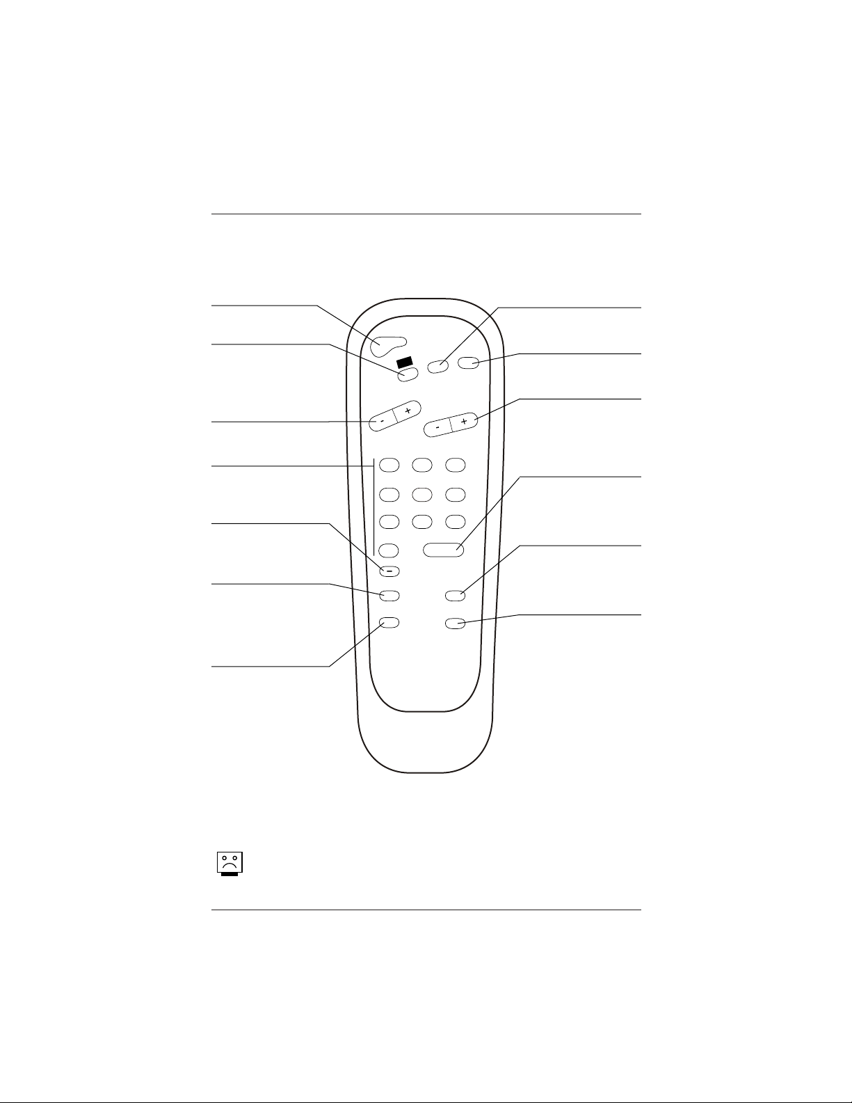
User Remote Control
POWER
FLSHBK
MUTE
CC
CHANNEL
VOLUME
ENTER
0
9
8
7
6
5
4
3
2
1
ALARM
CH PREVIEW
AUDIO
TIMER
CHANNEL (Up/Down)
Scroll available channels
(analog to digital) and
the Aux Channel (Audio /
Video source). User
Up/Down menu arrows
A list of the keys and their functions on the 6710V00108L user’s remote
supplied with the TV
POWER
Turns TV On or Off.
CC (Closed Captions)
Press to turn closed cap-
tions on/off. Press ENTER
to remove menu. In digital
captions, selects next cap-
tion language.
Remote Control part number
6710V00108L
VOLUME Down/Up
Adjusts the sound level.
User Left/Right menu arrows.
Number Keypad
Select channels directly;
key in channel numbers
and press ENTER.
(SLEEP) TIMER
Press repeatedly to
choose a TV turn-off time
up to 4-hours.
Use to set AM/PM on the
Alarm menu.
-DASH (-)
For entering digital chan-
nel numbers e.g. 7-1,
11-3 etc.
AUDIO
Selects available audio
languages for digital
channels only.
Audio Languages: Availability of audio languages are determined only by each broadcaster and
may not be available on all digital programs.
FLASHBK (Flashback)
Returns to the last chan-
nel viewed.
MUTE
Turns sound Off and On,
while the picture remains.
ENTER
Press to view the
Channel/Time/Audio
display or to remove any
on-screen display or menu.
ALARM
Press to display menu, fol-
low on-screen instructions
to set a time for the TV to
turn itself on.
CHANNEL PREVIEW
(Not functional for digital
channels - some models.)
Displays available analog
TV channels, allows hotel
guest access to the Aux
Channel and (if active)
the Guest Parental Control
menu: set V-Chip blocks
on analog channels only
to restrict both analog
and digital programming.
• Aux Channel allows the
guest to select the Audio
/ Video inputs. (Use the
A/V jacks on the back of
the TV as a source).
Page 10
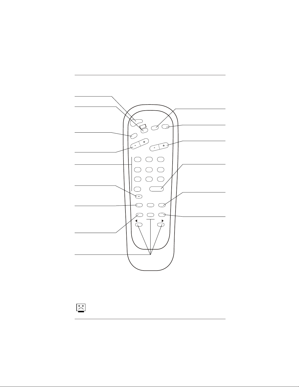
Installer Remote Control
POWER
FLSHBK
MUTE
CC
CHANNEL
VOLUME
ENTER
0
9
87
6
5
4
3
2
1
ALARM
CH PREVIEW
AUDIO
TIMER
MENU
SELECT
ADJ
ADJ
TV/FM
Keys descriptions and their functions for the optional Installer’s remote
Remote Control part number
6710V00108M
CHANNEL (Up/Down)
Scroll available channels,
(analog to digital) and
the Aux Channel
(Audio/Video source).
POWER
Turns TV On or Off.
VOLUME Down/Up
Adjusts the sound level.
Number Keypad
Select channels directly;
key in channel numbers
and press ENTER.
(SLEEP) TIMER
Press repeatedly to choose
a TV turn-off time up to 4-
hours. Use to set AM/PM
on the Alarm and On/Off
Timer menus.
FLASHBK (FLASHBACK)
Returns to the previously
tuned channel.
MUTE
Turns sound Off and On,
while the picture remains.
ENTER
Press to view the
Channel/Time/Audio
display or to remove any
on-screen display or menu.
ALARM
Press to display menu.
Follow on-screen instruc-
tions to set a time for the
TV to turn itself on.
TV/FM (Down Arrow)
Use for the menus down
arrow. If TV has FM radio,
toggles between TV-FM.
MENU/SELECT/ADJ
(Adjust Left/Right)
Selects and adjusts on-
screen menu options.
Press MENU repeatedly to
scroll through menus. Use
SELECT to choose options
and ADJ (Adjust)
Left/Right to change the
selected option.
Audio Languages: Availability of audio languages are determined only by each broadcaster and
may not be available on all digital programs.
CC (Closed Captions)
Press to turn closed cap-
tions on/off. Press ENTER
to remove menu. In digital
captions, selects next cap-
tion language.
-DASH (-)
For entering digital chan-
nel numbers e.g. 7-1, 11-
3 etc.
AUDIO
Selects available audio
languages for digital
channels only.
CHANNEL PREVIEW
(Not functional for digital
channels - some models.)
Displays available analog
TV channels, allows hotel
guest access to the Aux
Channel and (if active)
the Guest Parental Control
menu: set V-Chip blocks
on analog channels only
to restrict both analog
and digital programming.
• Aux Channel allows the
guest to select the Audio
/ Video inputs. (Use the
A/V jacks on the back of
the TV as a source).
Page 11
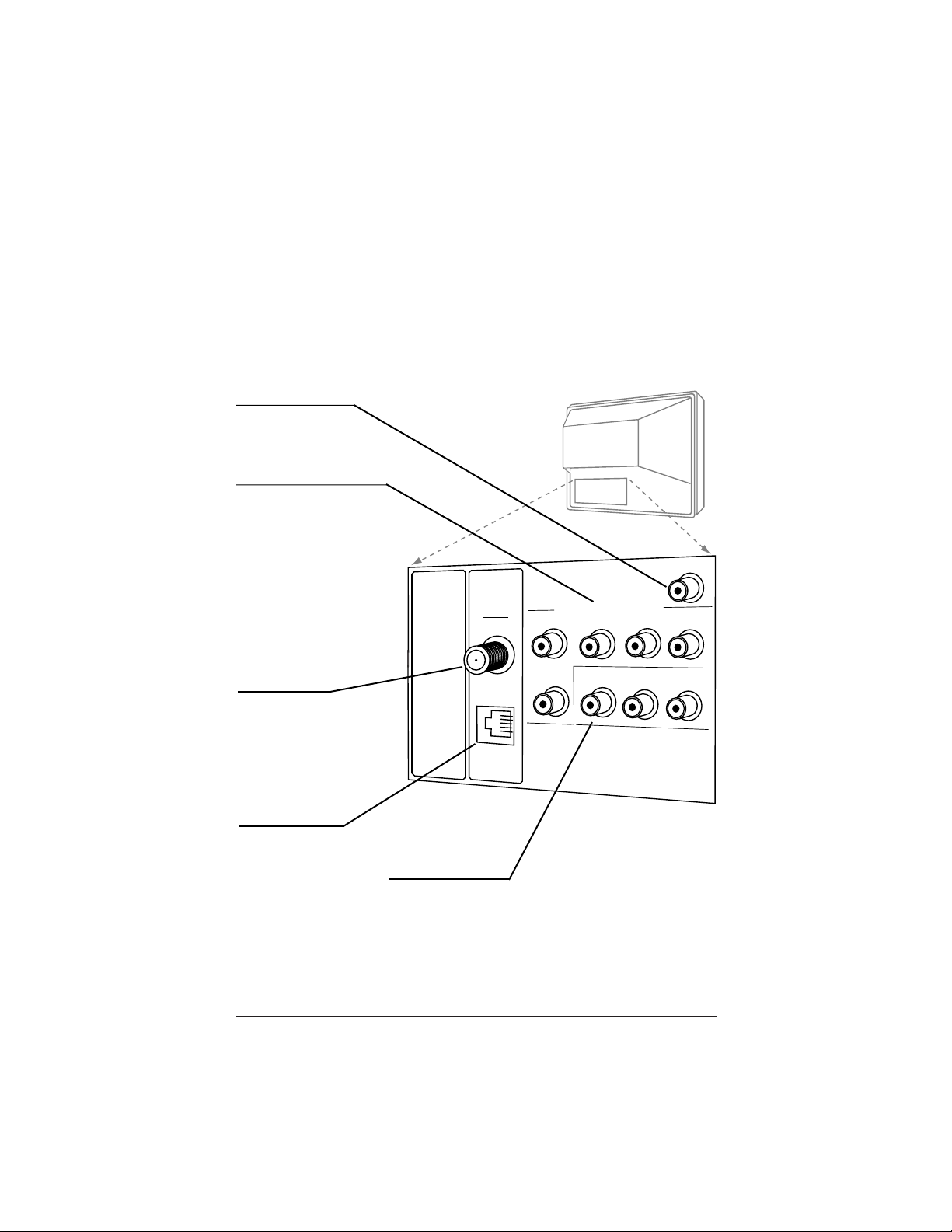
Typical
TV Back
M.P.I.
Antenna
Cable
Component Video Input
R Audio In L
R Audio L
Video In
Y
Pr
Pb
Matrix Out
Connections/Installation Overview
Use this page for reference when connecting analog or digital signal sources and other source equipment.
To hookup source equipment, refer to the next page; shows pages to go to for equipment hookup options.
Also, see the front connection panel hookup options on page 20.
Matrix Out
Connect external speaker
here.
Component Video
Inputs
Connect component
video equipment or a
DVD player here.
DVD Player 480i
Set Top Box 480i
MPI Port
Connect LT2002 clone
programmer to MPI port.
Video In R-Audio-L
Connect composite
Video-Audio source here.
Rear Connections Panel
Antenna/Cable
Connect analog off air antenna, analog
CATV signal or digital signal source.
This TV supports DCATV signal.
(DCATV = Digital Cable)
Page 12
IMPORTANT!!!
Use this page to decide where you need to begin your setup. First, find the line
below that best describes what you want to do, then go to that page number. Go
to additional pages as required.
Off Air Antenna Only
If you are using an antenna and no other equipment, go to . . . . . . . . . . . . . . . . . . . . . . . . . page 13
Cable Service Only
If you have cable service and no other equipment, go to . . . . . . . . . . . . . . . . . . . . . . . . . . . page 13
Off Air Antenna with VCR
If you are using an antenna and have a VCR, go to . . . . . . . . . . . . . . . . . . . . . . . . . . . . . . page 15
Cable Service with VCR
If you have cable service and a VCR, go to . . . . . . . . . . . . . . . . . . . . . . . . . . . . . . . . . . . . page 16
Component Video
If you want to hook up a component video device, go to . . . . . . . . . . . . . . . . . . . . . . . . . . page 17
Composite Video
If you want to hook up a composite video device, go to . . . . . . . . . . . . . . . . . . . . . . . . . . . page 18
External Speaker
Send the TV sound to an external audio system or monaural speaker, go to . . . . . . . . . . . . . . page 18
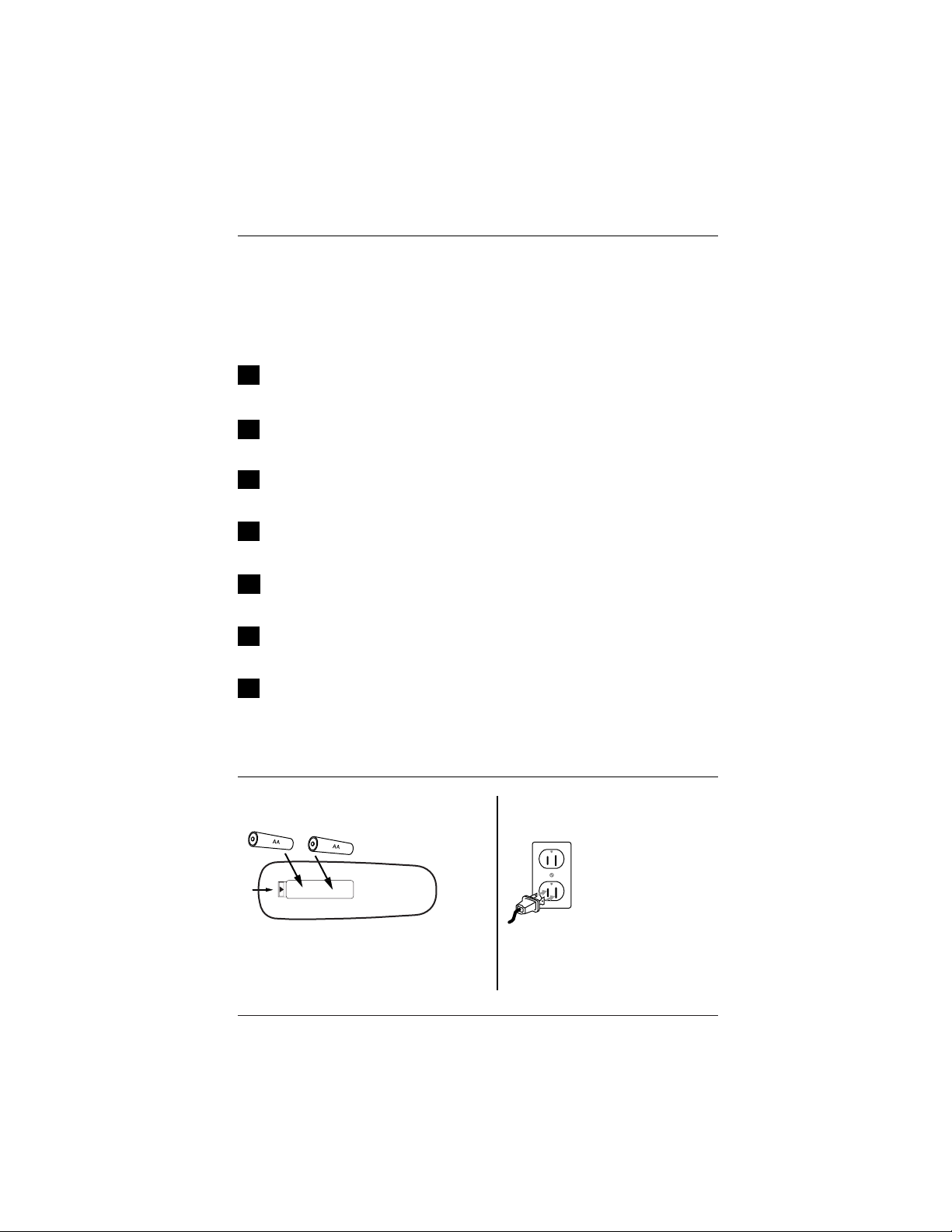
Install Batteries in User Remote Control
Hookup Directory
Back of
Remote
Remove the back of the remote and install
two high-quality AA batteries.
120 Volt
60 Hz AC
Plug TV into Wall Power Outlet
After all connections
have been made, plug
the TV and all system
equipment into power
sources as applicable.
This TV is designed to
operate on standard
current, 120-volt 60
Hertz AC power. Do not
attempt to operate it
on DC Current.
Available Source Connections
Page 13
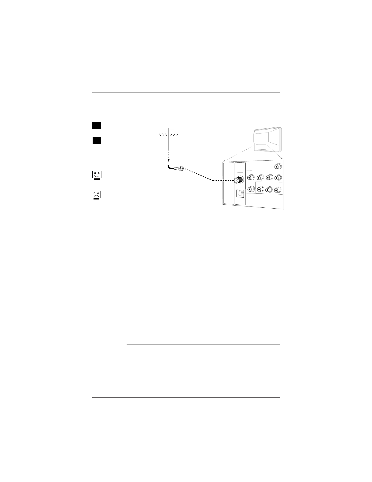
Antenna
Cable
Typical
TV Back
M.P.I.
Component Video Input
R Audio In L
R Audio L
Video In
Y
Pr
Pb
Matrix Out
RF Coaxial Wire
(75ohm)
Antenna
Hook Up an Off Air Antenna
1
2
Locate the Antenna/Cable
jack on the back of the TV.
Connect the antenna that
runs from the wall directly to
this jack, according to the
connection diagram shown
to the right.
If you have a 75 ohm RF
cable, then you don’t need
any adapters!
A 300 to 75 ohm adapter is
not included with the LG TV.
Over the Air Antenna
Mini Glossary
75 ohm The wire that comes from an off-air antenna or cable service provider. Each end
RF Cable looks like a hex shaped nut with a wire sticking through the middle, and it screws
onto the threaded jack on the back of the TV.
300 to (Not shown) A small device that connects a flat two-wire 300 ohm antenna to a 75
75 ohm ohm RF jack. They are usually about an inch long with two screws on one end and a
Adapter round opening with a wire sticking out on the other end.
Connect an over the air signal source to the TV
Page 14
Antenna
Cable
Typical
TV Back
M.P.I.
Component Video Input
R Audio In L
R Audio L
Video In
Y
Pr
Pb
Matrix Out
Cable TV
Wall Jack
RF Coaxial Wire
(75ohm)
Antenna
Cable
Typical
TV Back
M.P.I.
Component Video Input
R Audio In L
R Audio L
Video In
Y
Pr
Pb
Matrix Out
Cable TV
Wall Jack
Cable Box
In
Out
RF Coaxial Wire
(75ohm)
3 4
output
switch
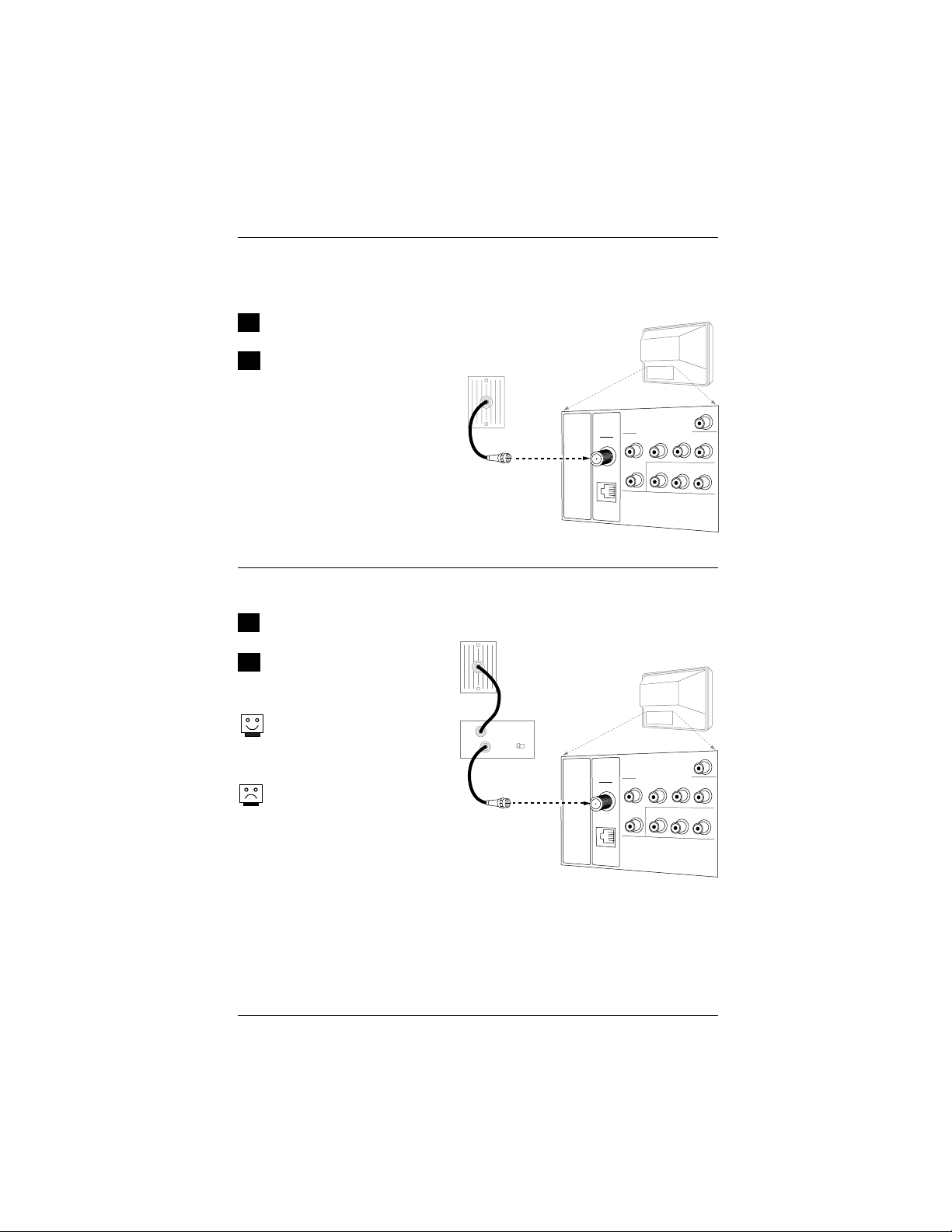
1
2
Locate the Antenna/Cable in jack
on the back of the TV set.
Connect the CATV or CADTV cable
that runs from the wall according to
the connection diagram shown to the
right.
Cable Service
Cable Service with a Cable Box
1
2
Locate the Antenna/Cable in jack
on the back of the TV set.
Connect the CATV/CADTV cable that
runs from the wall to the cable box
and TV according to the connection
diagram shown to the right.
If you’re using a cable box, tune
the TV to channel 3 or 4 and use
your cable box to changechannels.
If you’re using a cable box,
AutoProgram might only find
thechannel your cable service
is onusually channel 3 or 4).
Connect cable service to the TV
Hook Up Cable Service (CATV, CADTV)
Page 15
Antenna
Cable
Typical
TV Back
M.P.I.
Component Video Input
R Audio In L
R Audio L
Video In
Y
Pr
Pb
Matrix Out
In
Out
Audio
Video
3 4
VCR Back
VCR Back AV Panel
output
switch
A/V cables
not included
with TV
RF Coaxial Wire
(75ohm)
Antenna
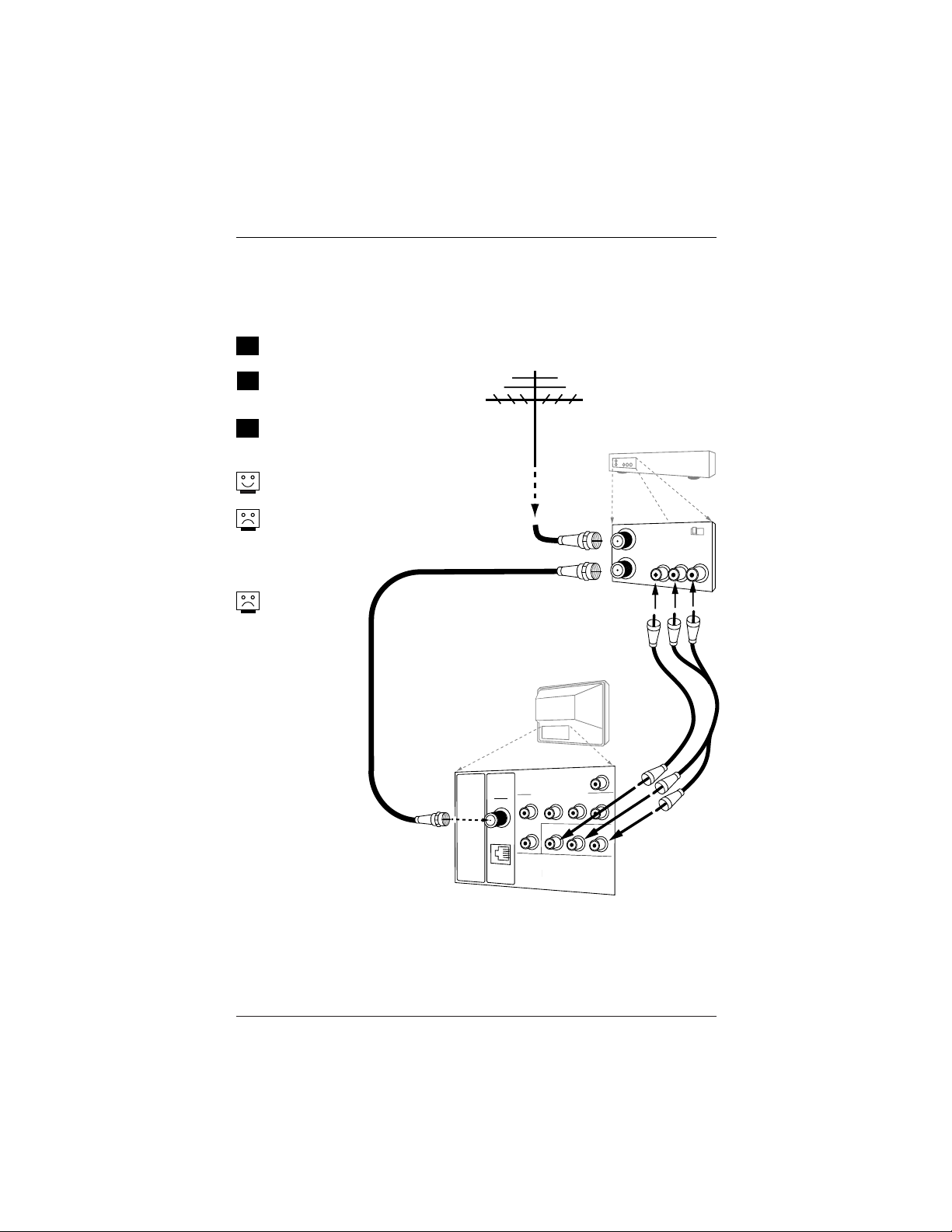
Hook Up an Off Air Antenna with VCR
1
2
Locate the Antenna/Cable In jack on the
back of the VCR.
Connect the antenna that runs from the wall
jack directly to this jack, according to the
connection diagram shown to the right.
Make the VCR to TV connections as indicated
in the illustration.
If you have a 75 ohm RF cable, then you
don’t need any adapters!
A 300 to 75 ohm adapter is not included
with the LG TV.
Over the Air Antenna with VCR
Connect an over the air signal source to the VCR and TV
No A/V cables are
included with the
TV. Without A/V
cables, most VCRs
will not play video-
cassettes in stereo
sound.
3
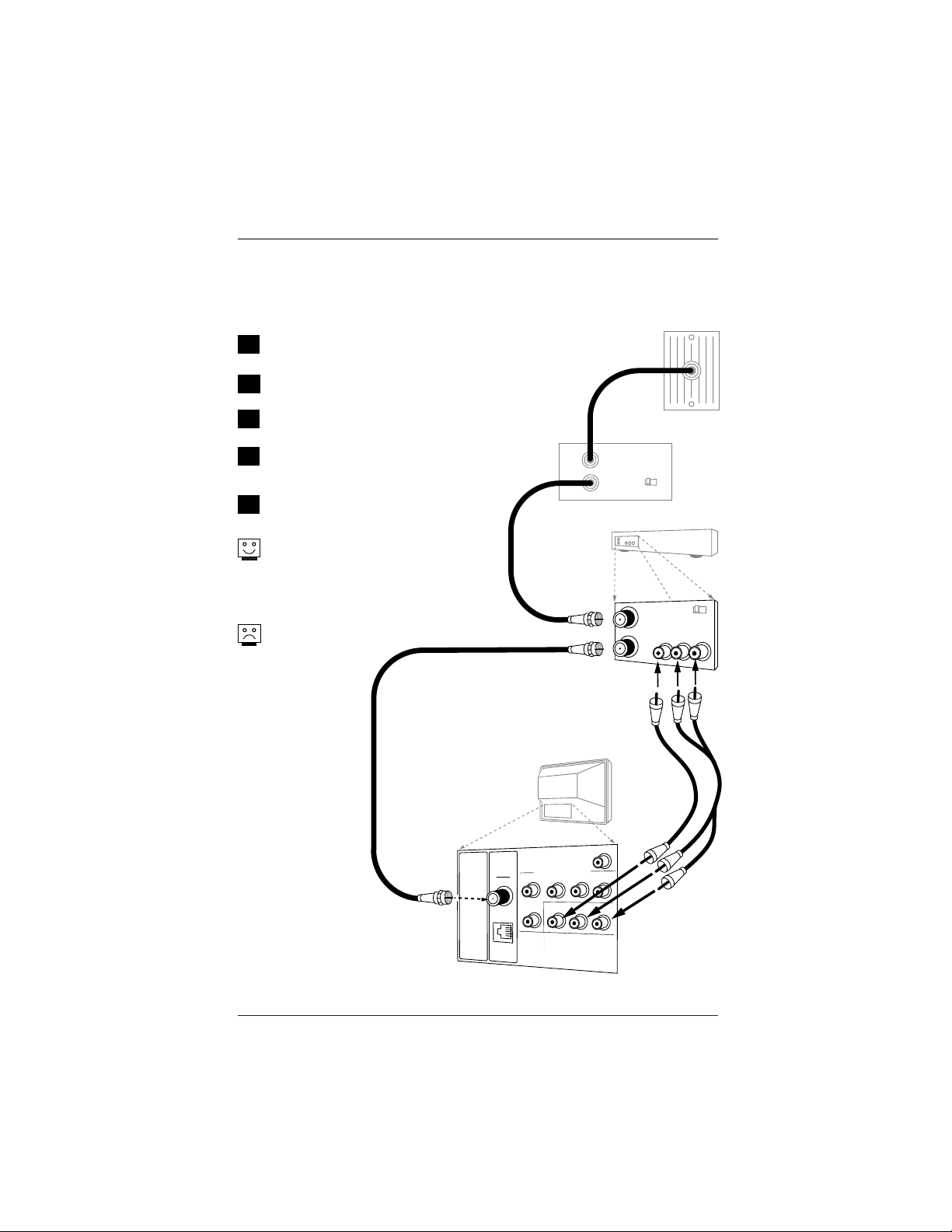
Page 16
Cable TV
Wall Jack
Cable Box
In
Out
3 4
Output
Switch
Antenna
Cable
Typical
TV Back
M.P.I.
Component Video Input
R Audio In L
R Audio L
Video In
Y
Pr
Pb
Matrix Out
In
Out
Audio
Video
3 4
VCR Back
VCR Back AV Panel
output
switch
A/V cables
not included
with TV
RF Coaxial Wire
(75ohm)
Hook Up a Cable Box with VCR
1
2
Locate the In jacks on the cable box and the
VCR.
Connect a 75 ohm cable between the cable box
wall jack and Cable In on the cable box.
Connect a 75 ohm cable from the Cable out jack
on the cable box to the Ant In jack on the VCR.
Connect a 75 ohm cable between the VCR out
jack on the VCR and the Antenna/Cable In jack
on the TV.
Make the other VCR-TV connections as indicated
in the illustration.
For cable service without a cable box, connect a
75 ohm cable between the cable wall jack and
the VCR In jack.
Cable Service with VCR
Connect a cable box and VCR to the TV
No A/V cables are
included with the TV.
Without A/V cables,
most VCRs will not
play videocassettes in
stereo sound.
3
4
5
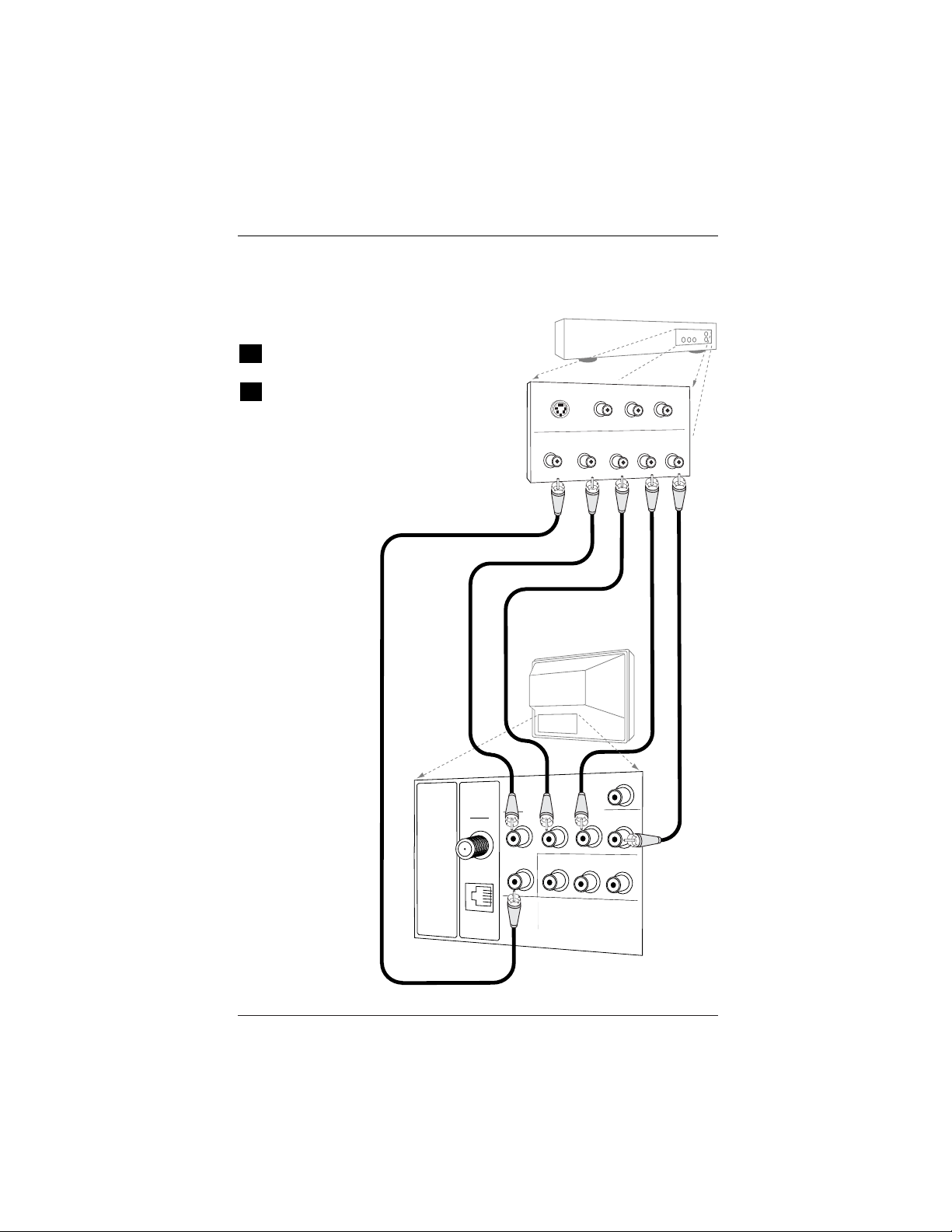
Page 17
Antenna
Cable
Typical
TV Back
M.P.I.
Component Video Input
R Audio In L
R Audio L
Video In
Y
Pr
Pb
Matrix Out
DVD Player with
Component Video
S-VIDEO OUT VIDEO R-AUDIO L-/MONO
Hook Up Component Video
1
2
Locate the component output jacks on the back
of the DVD player.
Connect the component output jacks on the DVD
player to the TV component input jacks, according
to the connection diagram shown to the right.
Component Video
Connect a component video source to the TV
COMPONENT VIDEO OUT
Y
Pr
Pb
R
L
Antenna
Cable
Typical
TV Back
M.P.I.
Component Video Input
R Audio In L
R Audio L
Video In
Y
Pr
Pb
Matrix Out
Audio cables
not included
with TV
Composite
Audio/Video
Device
Audio Out
Video Out
Right
Left
Audio cable
not included
with TV
Audio In
Speaker Back
Antenna
Cable
Typical
TV Back
M.P.I.
Component Video Input
R Audio In L
R Audio L
Video In
Y
Pr
Pb
Matrix Out
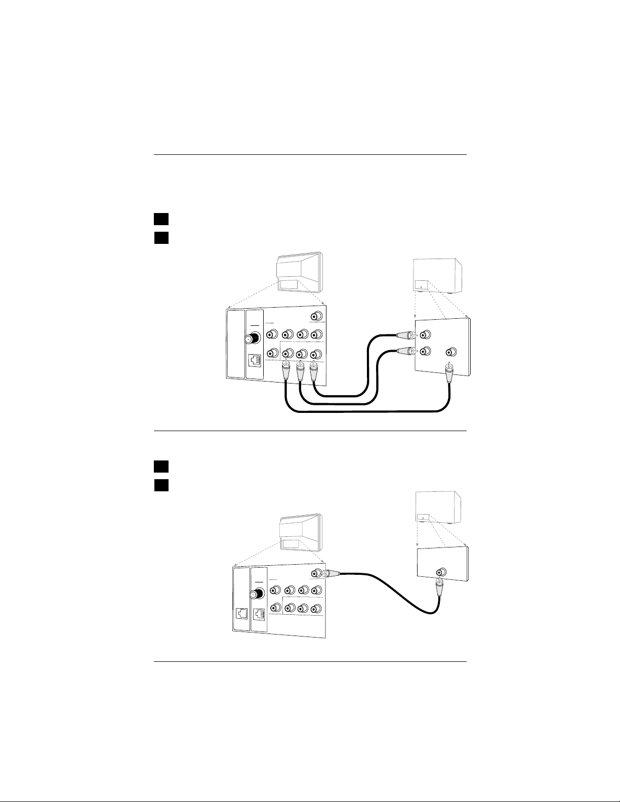
Page 18
Hook Up Composite Audio/Video & External Speaker
1
2
Locate the composite audio/video input jacks on the TV.
Connect the composite audio/video input jacks to a compos-
ite audio/video device as shown in the illustration.
Composite Audio/Video
Connect the TV to an composite audio/video source and an external speaker
1
2
External Speaker
Locate the Matrix Out jack on the back of the TV.
Connect the Matrix Out jack to an external speaker or
audio amplifier as indicated in the illustration.
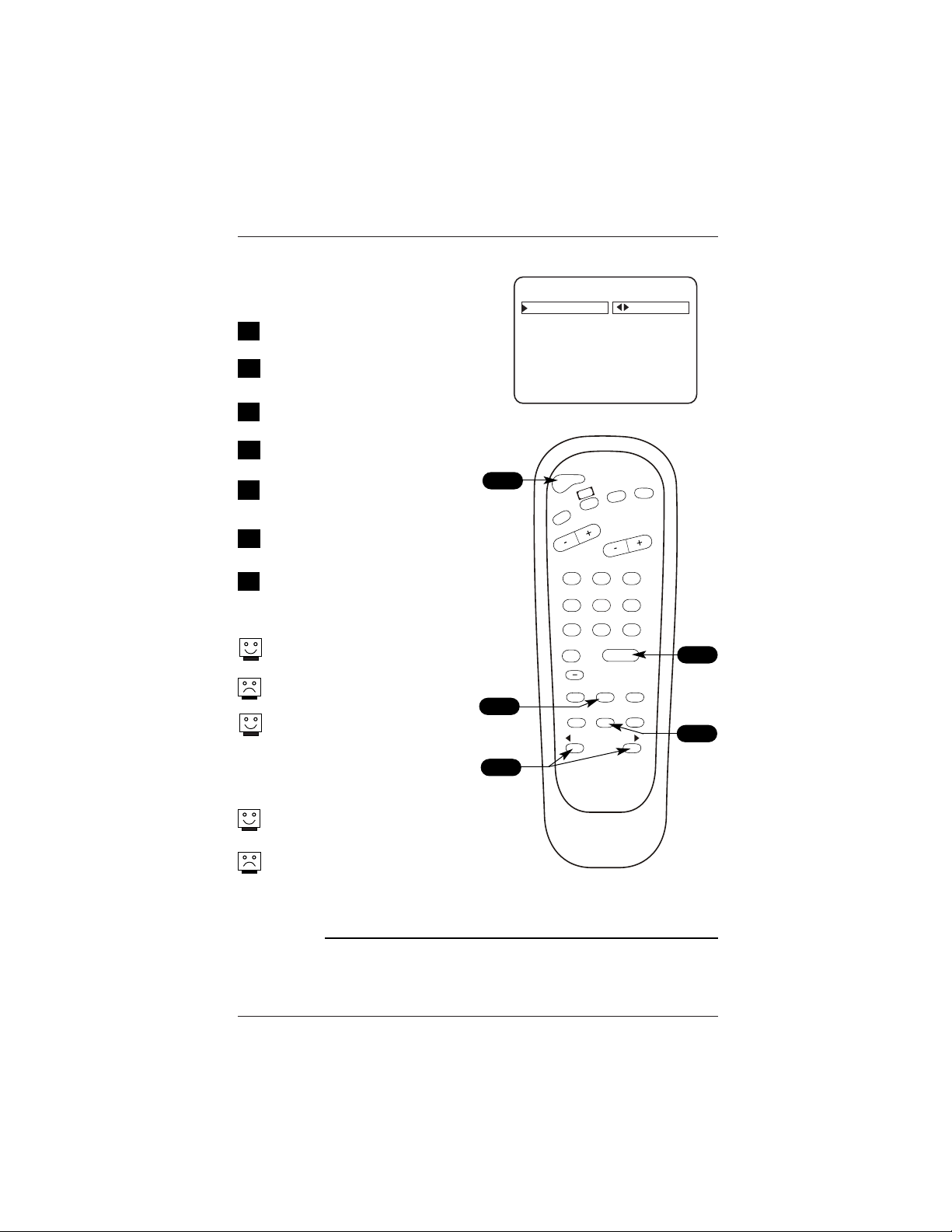
Page 19
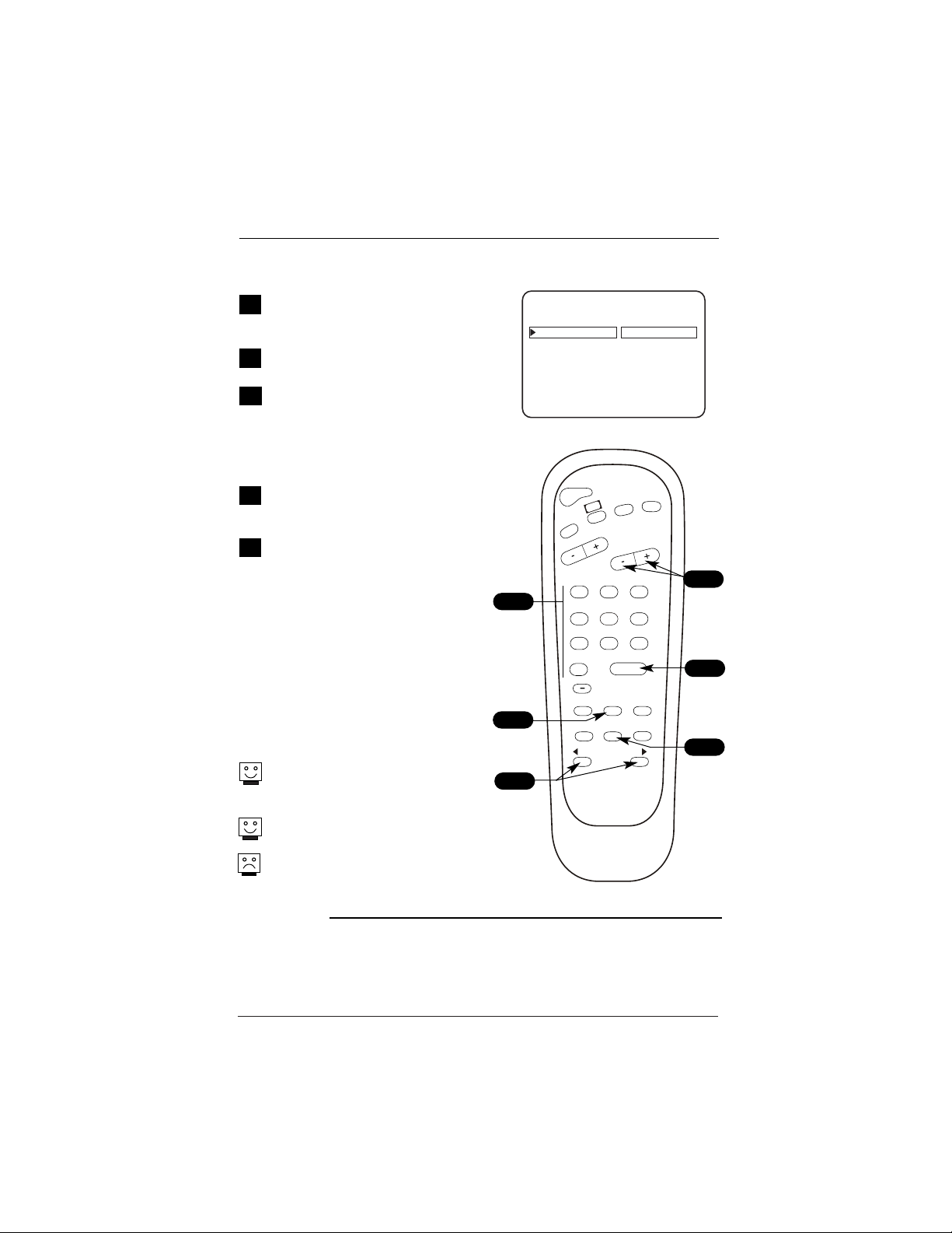
Auto Program (Channel Search)
Using the optional Installer’s remote control,
press POWER to turn the TV on.
Press MENU repeatedly until the Setup menu
appears.
Using SELECT on the remote control, high-
light Auto Program on the menu.
Press the Right or Left ADJ arrow to go to
the Auto Program menu.
Using SELECT, choose either Cable TV or
Off-Air Antenna on the menu (see Mini Glossary
below).
Press the Right or Left ADJ arrow to begin
the Channel Search.
Press ENTER when the channel search is
completed. This is when the progress bars
are filled and a message “COMPLETED SUC-
CESSFULLY” appears on the screen.
Auto Program finds channels being received
by the TV tuner.
Cable will not work unless you subscribe to a
cable service.
After the channel search is complete, use
the features on the following pages to:
Add/delete/blank channels, Include channel
labels, so that they appear on the channel /
time / audio display. Choose from the preset
label selections.
Use Auto Program to specify over-the-air Antenna or Cable
Service incoming signal source and automatically store all
of the channels found by the channel search in non-
volatile memory. (Do not connect any device to front
video input while TV is in channel search mode.)
1
2
Mini Glossary
On the Auto Program Menu, select:
OFF AIR ANTENNA If only over-the-air channels are available, select Off-Air Antenna.
CABLE TV If you subscribe to a cable service, select Cable TV.
POWER
FLSHBK
MUTE
CC
CHANNEL
VOLUME
ENTER
0
9
87
6
5
4
3
2
1
ALARM
CH PREVIEW
AUDIO
TIMER
MENU
SELECT
ADJ
ADJ
TV/FM
AUTO PROGRAM
ADD/DEL/BLNK
CH. LABELS
SOURCE NAME
CLOCK SET
TIMER
CAPTI
ONS
LANGUAGE
TO PROGRAM
SETUP MENU
1
2
3/5
4/6
3
4
5
6
7
7
Channel search for digital channels will follow
the analog channel search automatically.
After changing from CABLE TV to OFF AIR ANTENNA
(and vice versa) it is necessary to perform the auto program
function in order to get the proper digital information.
Note: If necessary, select tuning band (Cable 1 or Broadcast 0) for Installer Menu item 3-I Band-AFC before doing
a channel search.
Page 20
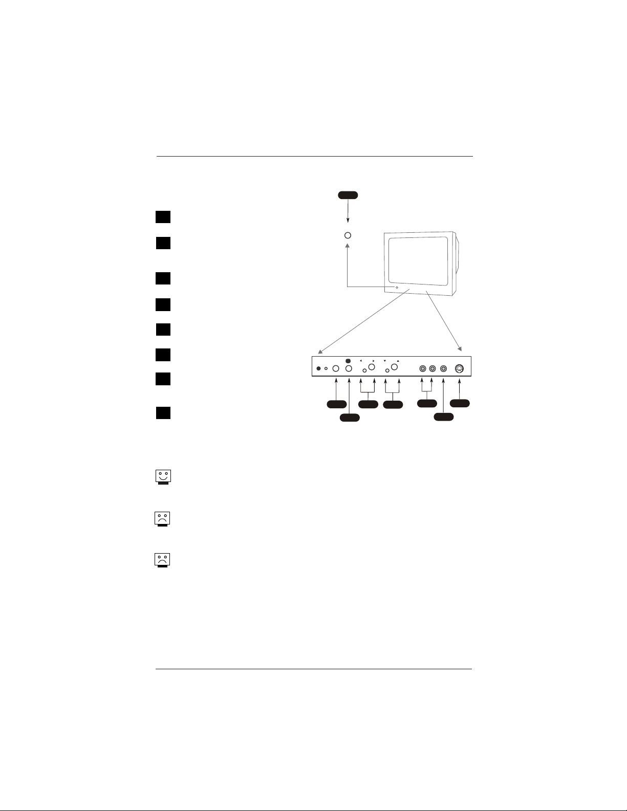
Front Panel Controls / Source Inputs
A
B
Using the front panel controls to operate the TV
C
On/Off
Turns TV on and off.
CC (Captions/Text)
Turns selected caption/text option
on and off.
Menu
To display on screen menus.
Volume (Left/Right)
Decreases/increases sound level.
Channel (Down/Up)
Chooses next available channel.
R - Audio - L (In)
Right/Left Channel audio input jacks.
Video (In)
Input for a video signal from
auxiliary equipment.
S-Video (In)
Input for an S-Video signal from
S-Video (Y-C) equipment.
The front Video jacks are Auto Sense source connections. With
cables connected, the TV will automatically change its source
setting to CAMPORT, or FRNT Y/C (Front S-Video) as
indicated on the channel-time display.
If you have a device connected to the front Video or S-Video
jack and the Auto sense source connection is turned on, you
will not be able to change channels using the TV tuner until you
have disconnected the device.
The front Video input jack has a priority over the front S-Video
input jack. If you have cables connected to both the front Video
jack and the front S-Video jack (and the Auto sense source
connection is turned on in the Installer menu), only the image
from the front Video input will be displayed.
D
F
G
H
E
B
A
C
Typical Front Panel Controls
MENU
VOL
R-AUDIO-L VIDEO S-VIDEO
CC
Typical TV
Front Panel
ON/OFF
CH
D
E
F
G
H
Page 21
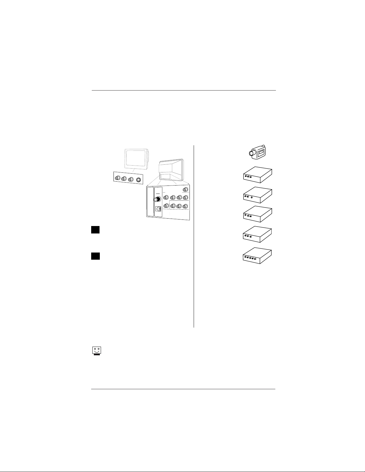
Picture/Sound Source Selection
1
2
Ty p i c a l
TV Ba c k
M.P.I.
Component Video Input
R Aud io In L
R A u d i o L
Video In
Y
Pr
Pb
Ma t rix Ou t
Video In
R- Au d io - L
S- V i d e o
Ante nna
Cable
Front/Rear
Connections
Panels
AUDIO/ S- I
VDEOO UT
R- A IUD O- L
O UTPUT
S- VI D EO
R- A IUD O- L
AUDIO/ IVDO
E OUT
R- A U DI O- L
AUDIO/ IVDEOOUT
IVDEO
R- A U DI O- L
COMPO ENNTIVDEO
R-AUDIO-L
-SVIDEO
Pb
YPr
VI DEO
Camcorder
VCR
S-Video
DVD
Audio/Video
Component Video
Note: The Installer by changing options in the Installer menu, can change the
default setup and determine which source connections are available.
• Auto Source Sensing Connections: The front video inputs Camport and S-Video (Y-
C), override all other source inputs. The Auto Sense feature is factory preset to be on
--for both front video inputs.
• The Source menu shows which picture and sound sources are available.
Hook up a device to front Video/Audio
In, to use this Auto Sense source.
Disconnect the device when finished.
To access other available sources, use
the Source menu or use Channel
Up/Down to select the Aux input.
Auto Source Sensing Connections override all other sources. The front Video
and S-Video in jacks are Auto Sense source connections. If you have devices
connected to these jacks you will not be able to change channels using the TV
tuner until you have disconnected those devices.
Connectable sources
See pages 9 - 16
Antenna/Cable
Camport (Front Video input)
Front S-Video
Aux Video (Rear Video Inputs)
Component Video
Page 22
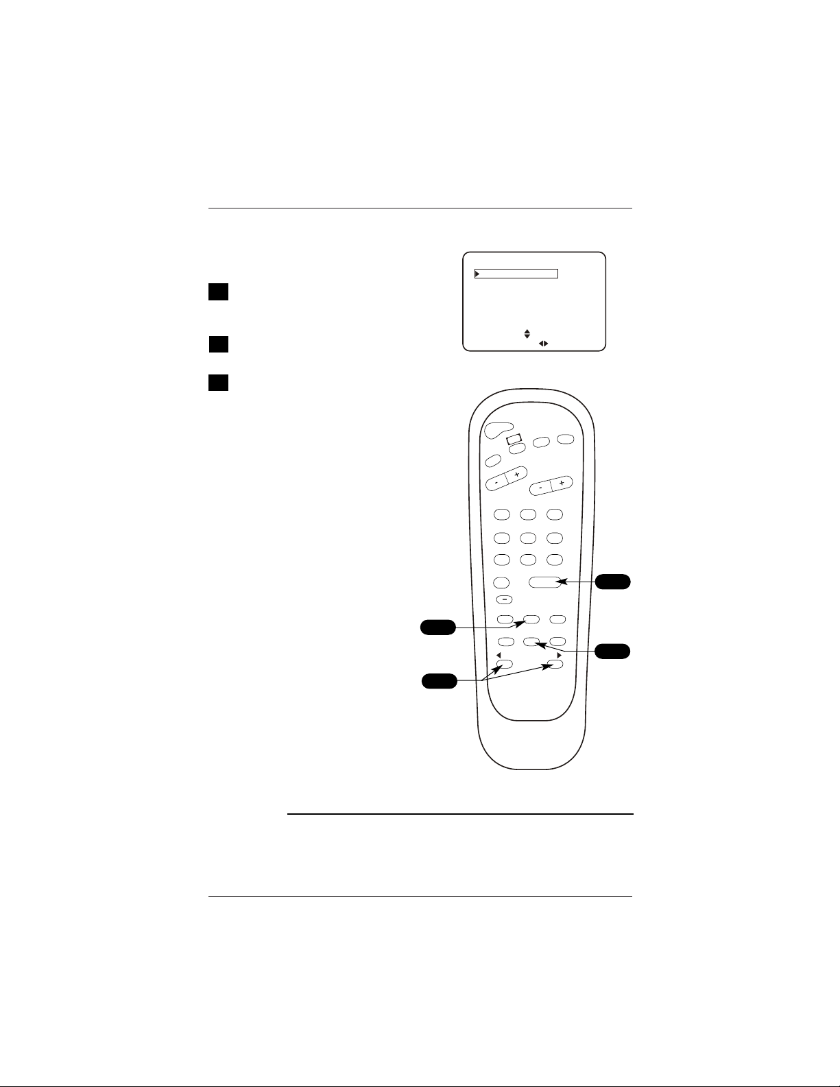
Source Menu
Press MENU repeatedly on the
optional Installer’s remote until
the Source menu appears.
Choose the input source using
SELECT.
Press ENTER, or the Left/Right ADJ
arrow to go to the selected source
and to remove the menu.
Notes
• The selection of the sources
appearing in the Source menu may
vary depending on the installation
setup for Auto Sense sources in
the Installer menu.
• If a source is not connected, the
not available message is displayed.
Selecting picture and sound sources
1
2
Mini Glossary
SOURCE Input or device providing picture and sound to the TV.
AUTO SENSE SOURCE Input(s) that the TV automatically switches to when connected.
SOURCE MENU
ANTENNA/CABLE
CAMPORT
F S-VIDEO
COMP (YPr Pb)
REAR AUX.
PRESS
TO CHANGE
PRESS ENTER OR
TO ACTIVATE
3
POWER
FLSHBK
MUTE
CC
CHANNEL
VOLUME
ENTER
0
9
87
6
5
4
3
2
1
ALARM
CH PREVIEW
AUDIO
TIMER
MENU
SELECT
ADJ
ADJ
TV/FM
1
2
3
3

Page 23
On-Screen Menus/Displays Overview
Descriptions of the menus and on-screen status displays
Using MENU and the other keys indicated on the optional Installer’s remote,
the user can access the menus/displays described below.
On-Screen Menus
Setup Menu Adjusts the basic characteristics of the TV.
Auto Program 19 Automatically finds and stores active channels to scroll
through using Channel Up/Down.
Source Menu 22 Selects input sources to see and hear on the TV.
Add/Del/Blnk 25 Manually pick and choose which active channels will
appear when using Channel Up/Down.
Channel Labels 26 Labels the channels with their network names (ABC, CBS,
HBO, etc.).
Source Name 27 Create new names for the sources’ on-screen displays.
Allows the installer to customize sources names.
Clock Set 28 Sets the time on the TV.
Timer 29 Sets the TV’s automatic turn On/Off times.
Captions 30 Analog-Digital Captions (Caption/Text) Setup Overview.
Captions Menus 31 Analog-Digital Captions Menus Structures.
Language 33 Chooses the language the on-screen menus will appear in.
Audio Menu 34 Customizes the sound. The options are: Bass, Treble,
Balance, Audio Mode/Audio Language, Front Surround,
SoundRite, Audio Pref.
Digital Audio 35 Digital audio language selection.
Video Menu 36 Customizes the picture. The options are:
Contrast, Brightness, Color, Tint, Sharpness, Picture Pref,
and Aspect Ratio (Aspect Ratio only for Digital Channels).
Parental 37 Allows user to block program content or the A/V sources
Control Menu for up to 99 hours, with the use of a password.
Other Menus and On-Screen Displays
Volume 24 Shows current sound level setting; press VOLUME Up/Down
to activate.
Channel/Time 24 Shows the current time, channel, video and type of
incoming audio signal, or mute, and XDS info; press
ENTER to activate.
Ch Preview 24 Displays the available channels list; press CH PREVIEW.
(Only Analog Channels are displayed not digital).
Captions/Text 24 Turns selected Caption/Text option On and Off; press CC to
activate.
Sleep Timer 24 Sets the time the TV will turn off.
Ghost Channel 24 Shows the current channel number in red scrolling down
the screen. Refer to Installer menu to turn off.
Alarm 24 Sets a time for the TV to automatically turn itself on.
5 - - - -
9 - - - -
20 - - - -
32 - - - -
2 - - - -
AUX - - - -
VOLUME
Ch 25 - PBS
7:15 PM
MONO
XDS Information As Available
CHANNEL PREVIEW
CH
TO SELECT, ENTER TO QUIT
CC FOR PARENTAL CONTROL
SLEEP TIMER
OFF
PRESS TIMER
CC CAPTION 1 IS ON
ALARM MENU
TIME NOW 3:11 PM
6:10 AM
TIMER
PRESS DIGITS TO SET TIME
TIMER TO SELECT AM/PM
CC CAPTIONS UNKNOWN
CC CAPTIONS 1
LENGTH 00:32 TIME LEFT 00:42
Page 24
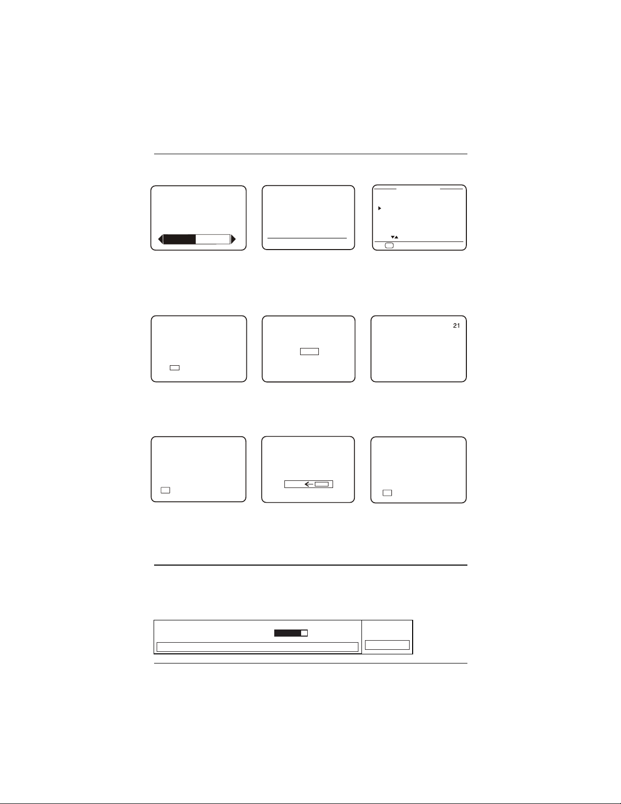
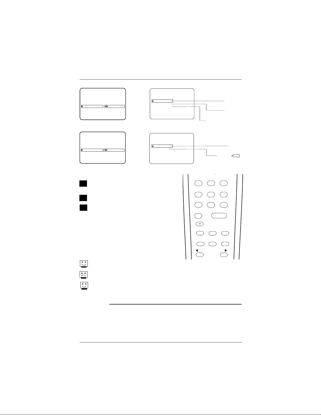
Other Menus and On-Screen Displays
Press the remote keys indicated below to access these menus and displays
Volume Display
Press VOLUME. Shows current
sound level.
Closed Captions Menu
Press CC. Turns selected option
on or off for both analog and
digital captions. See Caption /
Text pages to set up options.
Captions Unknown Display
Press CC, if captions are not
known, this display appears.
Channel/Time/Audio Display
Press ENTER. Shows selected
channel or source, time if the
clock is set, incoming audio
signal, and XDS info if avail-
able on program. For XDS, wait
5 seconds then press ENTER.
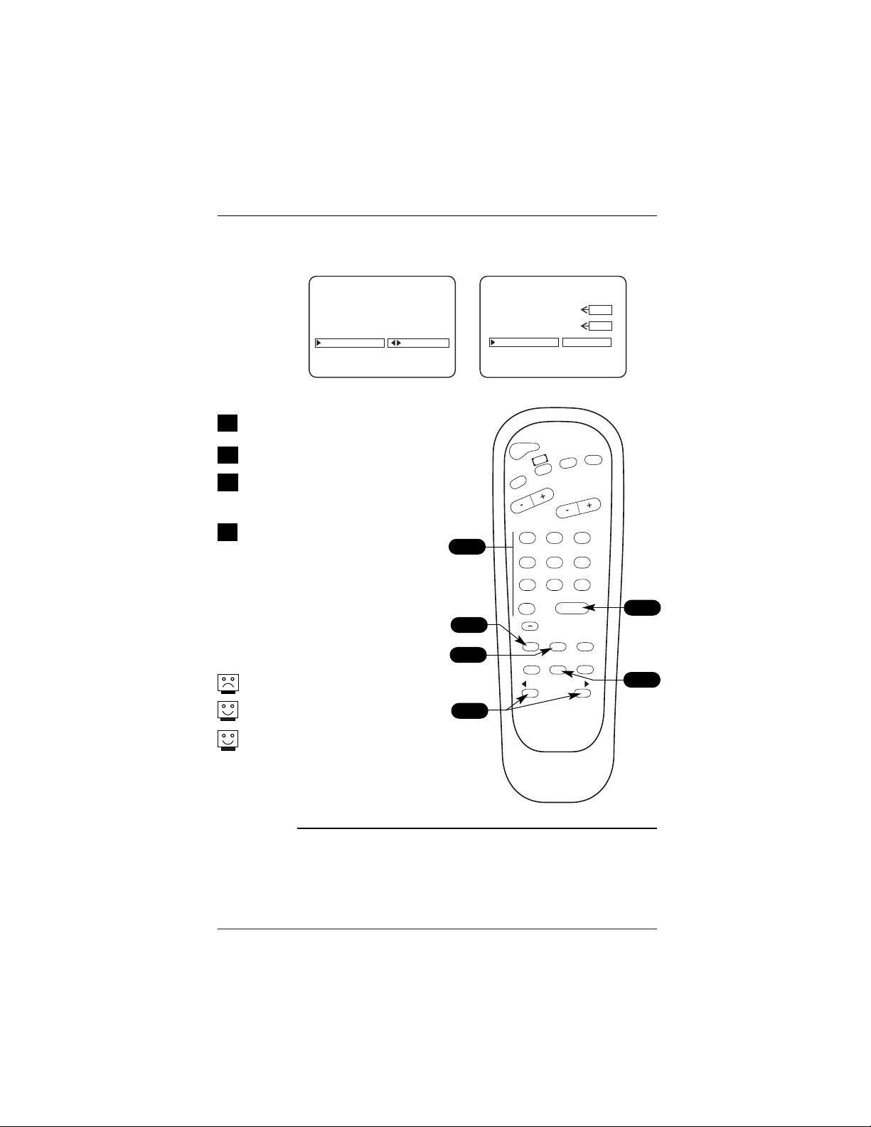
Sleep Timer Menu
Press TIMER. Shows remaining
time before TV turns off. Set a
preset turn-off time from 10
minutes up to 4 hours.
Alarm Menu
Press Alarm. Sets a time for
the TV to automatically turn
itself on.
Ch Preview Menu
Press CH PREVIEW. Shows list
of TV Analog Channels, AUX
source, and provides access to
the Parental Control menu.
(Some models - not functional
on digital channels.)
Ghost Channel Display
Channel number appears in red
on the right side of the pic-
ture and slowly scrolls down-
ward. To disable Ghost
Channel, see Installers menu.
Digital Captions Menu
Press CC to scroll each digital
captions service, if available.
News and local programming 5:50 PM
Thu Jan 19, 2007 4:00 PM 6:00 PM
DTV 66-1
Dolby Digital HD
Multi-lingual 16:9 1080i TV-PG
Digital Captions On-screen Display
Press ENTER twice to see the on-screen display for digital channels. Reveals channel number and program
details: Title, day, time, languages available, audio options available, video formats available, Closed cap-
tions options available, etc.
Page 25
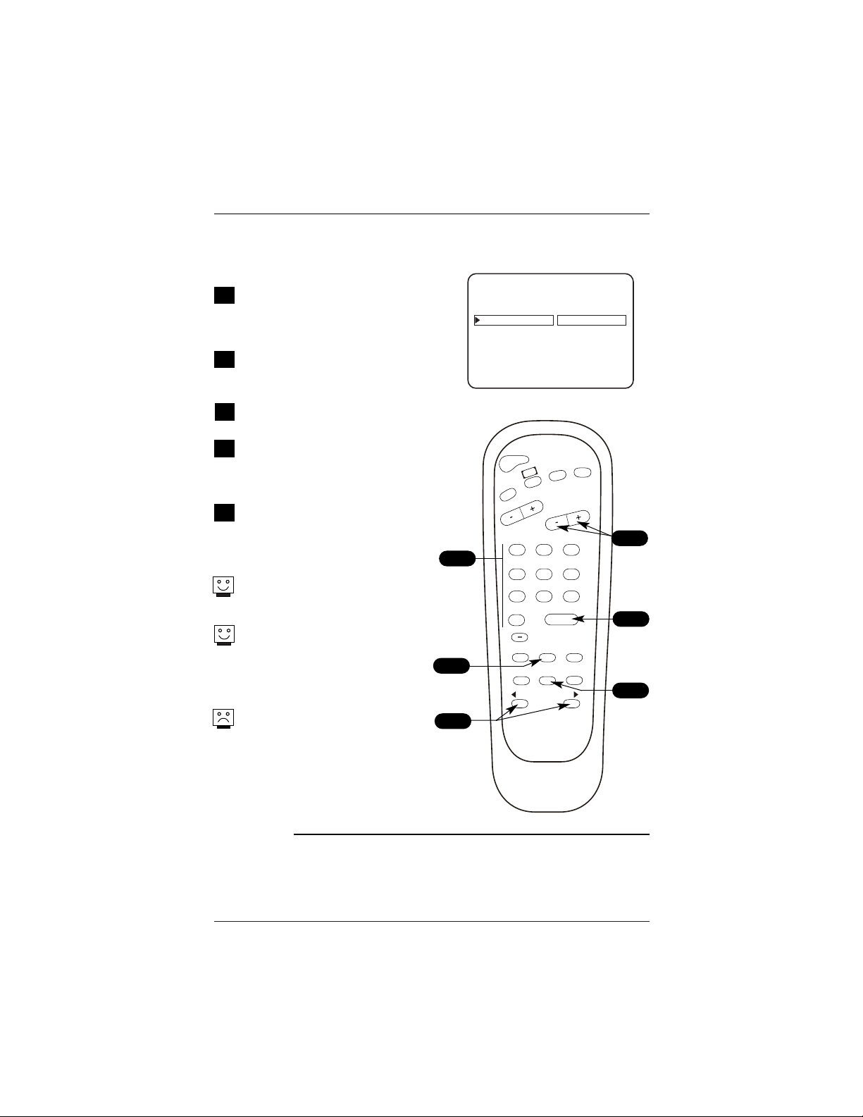
Use the MENU key on the optional
Installer’s remote to access the Setup
menu.
Use SELECT to highlight the
Add/Del/Blnk option.
Using either the NUMBER keypad and
ENTER or the Channel Up/Down arrow
on the remote, select a channel.
(If adding a deleted channel, you will
need to use the NUMBER keypad and
ENTER.)
Using the Right/Left ADJ arrow, spec-
ify whether the channel is to be
Added, Deleted or Blank.
To continue, select another channel
and repeat Step 4. When you are fin-
ished, press ENTER to remove menu.
Adding Aux, VCR3, VCR4, to the Channel Preview
List. Go to the Setup menu, select the
Add/Del/Blnk option. Use Channel Up/Down to
select Ch 126-0 for VCR3 (Ch 127-0 for VCR4)
and choose Added.
Note: If the option was turned off in the Service
menu, you will have to reinstate it before it can
appear as an option in the Channel Preview list.
Note: You can specify Add, Delete or Blank for
VCR3, VCR4, and Aux. Caution: If you delete Ch
3-0, VCR3 (Ch 126-0) is also deleted. If you
delete Ch 4-0, VCR4 (Ch 127-0) is also deleted
and vice versa.
Channel scanning up: Analog Channels, Digital
Channels, VCR3, VCR4 and Aux. Use Channel Up
to scan all channels, Ch Preview for analog only.
Channel scanning down, reverse order of above.
If you delete a channel, it isn’t gone for good.
Just select it using the NUMBER keypad on the
remote, or add it later.
To add digital channels that were deleted, run
Auto Program again.
Add/Delete/Blank Channel Setup
Fine-tune the channel selection list
CH 30-1 ADDED
SETUP MENU
AUTO PROGRAM
ADD/DEL/BLNK
CH. LABELS
SOURCE NAME
CLOCK SET
TIMER
CAPTIONS
LANGUAGE
POWER
FLSHBK
MUTE
CC
CHANNEL
VOLUME
ENTER
0
9
87
6
5
4
3
2
1
ALARM
CH PREVIEW
AUDIO
TIMER
MENU
SELECT
ADJ
ADJ
TV/FM
1
2
4
3/5
1
2
3
4
5
Mini Glossary
ADDED
Adds new channels to the list that the user can scroll through using Channel
Up/Down.
DELETED Removes channels for one reason or another from the channel scan list available
using Channel Up/Down.
BLANK Deletes the video but retains the audio.
3
3
Page 26
Using either the NUMBER keypad or
the Channel Up/Down arrows on the
optional Installer’s remote, select a
channel.
Press MENU repeatedly on the
optional Installer’s remote until the
Setup menu appears.
Choose the Ch Labels option using
SELECT.
Pressing either the Right/Left ADJ
arrow repeatedly, pick the label you
want from the available selections;
such as A & E.
To continue channel labeling, select
another channel or if you are fin-
ished, press ENTER to remove menu.
Some channels already provide a
channel label which is included
with the broadcast signal.
Labeling the channels helps identify
which familiar nationwide networks
are available. i.e., A & E - Arts and
Entertainment, CNN -News, ESPN -
Sports, HBO - Movies and so on...
Preset channel labels are not available
for Digital Channels.
Setting Preset Channel Labels
Selecting channel names from the preset Channel Labels
CH 7-0 ABC
SETUP MENU
AUTO PROGRAM
ADD/DEL/BLNK
CH. LABELS
SOURCE NAME
CLOCK SET
TIMER
CAPTIONS
LANGUAGE
POWER
FLSHBK
MUTE
CC
CHANNEL
VOLUME
ENTER
0
9
87
6
5
4
3
2
1
ALARM
CH PREVIEW
AUDIO
TIMER
MENU
SELECT
ADJ
ADJ
TV/FM
2
3
4
5
1
1
Mini Glossary
- - - - The 4 dashes will allow a channel label to appear; if one is
provided by the broadcaster.
NONE Prevents any channel label from appearing.
1
2
3
4
5
Page 27
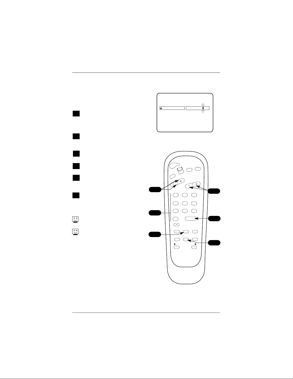
Using either the NUMBER keypad or
the Channel Up/Down arrows on the
optional Installer’s remote, select a
digital channel.
Press MENU repeatedly on the
optional Installer’s remote until the
Setup menu appears.
Choose the Ch Labels option using
SELECT.
Press Vol right to select the first
character space.
Use Ch Up/Down to select the char-
acter. Continue adding characters to
the label with Vol/Ch keys.
To continue channel labeling, select
another channel or if you are fin-
ished, press ENTER to remove menu.
Press and hold down Ch Up/Down
for faster character scrolling.
Use custom channel labels to iden-
tify your unique channel line up.
Setting Custom Labels for Digital Channels
Setting channel names for Channel Labels
AUTO PROGRAM
ADD/DEL/BLNK
CH. LABELS
CLOCK SET
TIMER
CAPTIONS
LANGUAGE
ABCDEF
SETUP MENU
PRESS VOL UP/DN TO SELECT CHAR
1
2
3
4
5
6
POWER
FLSHBK
MUTE
CC
CHANNEL
VOLUME
ENTER
0
9
87
6
5
4
3
2
1
ALARM
CH PREVIEW
AUDIO
TIMER
MENU
SELECT
ADJ
ADJ
TV/FM
3
1
2
4
5
6
CH 10-1
Page 28
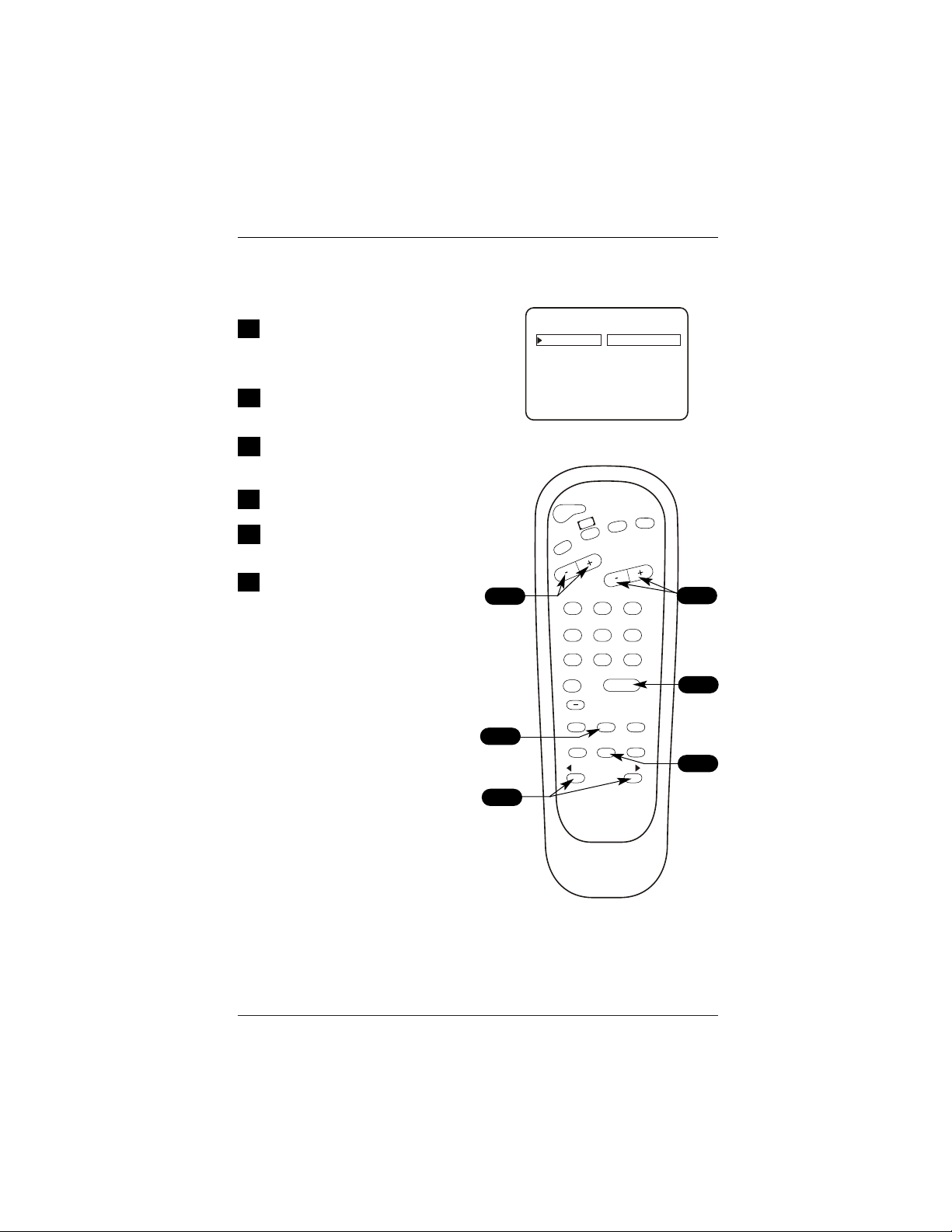
Press MENU repeatedly on the
optional Installer’s remote until
the Setup menu appears.
Choose the Source Name option
using SELECT.
Press the Left/Right ADJ arrow to
go to the Source Name menu.
Use SELECT to choose a Source.
Use Volume Up/Down to select
letter spaces (space blinks).
Use Channel Up/Down to change
the character to one of the 255
characters available.
(A blank letter space is available
after the “!” Symbol). Continue to
set the new source name, 11 digits
are available for each source.
Repeat from step 4 to rename
other sources. If finished, press
ENTER to remove menu.
Source Custom Name Menu
This menu enables the Installer to customize source names
1
2
3
4
5
SOURCE NAME
CAMPORT
F S-VIDEO
COMP. YPr Pb
AUX VIDEO
PRESS VOL UP/DN TO SELECT CHAR
MY CAMPORT
POWER
FLSHBK
MUTE
CC
CHANNEL
VOLUME
ENTER
0
9
87
6
5
4
3
2
1
ALARM
CH PREVIEW
AUDIO
TIMER
MENU
SELECT
ADJ
ADJ
TV/FM
1
2/4
3
3/4
6
5
6
Page 29
Clock Setup (Auto or Manual)
Mini Glossary
TIME A four-digit figure broken down into hours and minutes, used to enter the time
when setting the clock or programming timers.
HOURS First two digits that are entered when setting the clock or programming timers.
MINUTES The last two digits that are entered when setting the clock or programming timers.
TIMER Chooses AM or PM when setting the clock.
Clock Auto/Manual Operating Modes Setup
On the optional Installer’s remote, use MENU, SELECT, and
the ADJ Left/Right arrows to choose and set up the Clock
menu options.
Use the number keypad, or the Left/Right ADJ arrows, to
set the time.
Use TIMER to set AM/PM.
Clock Set Auto: TV automatically sets the time.
Time Zone: Installer can choose the time
zone or have the TV set it automatically.
Day. Savings: Installer can choose to have
daylight savings adjust the clock time one
hour, or have the TV adjust it automatically.
Manual: Installer sets the time on the clock.
• Press ENTER repeatedly to remove menus.
AUTO PROGRAM
ADD/DEL/BLNK
CH. LABELS
SOURCE NAME
CLOCK SET
TIMER
CAPTIONS
LANGUAGE
TO SET CLOCK
SETUP MENU
AUTO PROGRAM
ADD/DEL/BLNK
CH. LABELS
SOURCE NAME
CLOCK SET
TIMER
CAPTIONS
LANGUAGE
TO SET CLOCK
SETUP MENU
CLOCK SET
TIME ZONE
DAY. SAVINGS
CLOCK MENU
CLOCK MENU
CLOCK SET
TIME SET
AUTOMATIC
OFF
ON
AUTOMATIC
AUTOMATIC
EASTERN
CENTRAL
MOUNTAIN
PACIFIC
MANUAL
10:43 AM
TIMER
The clock can also be set using 24 hour “military time.” For p.m. Settings add 1200. For example,
to set 6:30 p.m., add 1200 to 630, = enter 1830.
For Auto Clock Set to work, the TV must be tuned to a local analog (not digital) PBS station. If the
TV does not set the time, set the clock time manually.
Clock time can be set using either the number keypad or the Left/Right ADJ arrows. Use TIMER to
set AM/PM.
ENTER
0
9
87
6
5
4
3
2
1
ALARM
CH PREVIEW
AUDIO
TIMER
MENU
SELECT
ADJ
ADJ
1
2
3
Page 30
On the optional Installer’s remote, press MENU
repeatedly until the Setup menu appears.
Press SELECT repeatedly to highlight the Timer
option, press the Left/Right ADJ arrow.
Use SELECT to choose an option. Use the num-
ber keypad and/or the Left/Right ADJ arrows to
enter the times. Use the TIMER key to set
AM/PM.
Press ENTER to remove menu and return to TV
viewing.
Your options are:
• On Time: Sets a time that the TV will turn
itself On each day.
• Off Time: Sets a time that the TV will turn
itself Off each day.
• On/Off Timer: Enables or disables the On/Off
Timer functions. (The On/Off Timer can be dis-
abled but the settings will be retained.)
The clock must be set before the Timers will
function.
The Off Timer can be used to turn the TV off at
the preset time.
The On Timer does not have to be set to use the
Off Timer feature.
On-Off Timers Setup
Set up On/Off Timers
Note: On/Off Timers operate independently
AUTO PROGRAM
ADD/DEL/BLNK
CH. LABELS
SOURCE NAME
CLOCK SET
TIMER
CAPTIONS
LANGUAGE
TO SET TIMER
SETUP MENU
ON TIME
OFF TIME
ON/OFF TIMER
ON
TIMER
9:00 AM
7:00 PM
TIMER
TIMER
POWER
FLSHBK
MUTE
CC
CHANNEL
VOLUME
ENTER
0
9
87
6
5
4
3
2
1
ALARM
CH PREVIEW
AUDIO
TIMER
MENU
SELECT
ADJ
ADJ
TV/FM
1
2/3
2/3
4
1
2
3
4
3
3
Mini Glossary
TIME A four-digit figure broken down into hours and minutes, used to enter the time
when setting the clock or programming timers.
HOURS First two digits that are entered when setting the clock or programming timers.
MINUTES The last two digits that are entered when setting the clock or programming timers.
TIMER Chooses AM or PM when setting the clock.

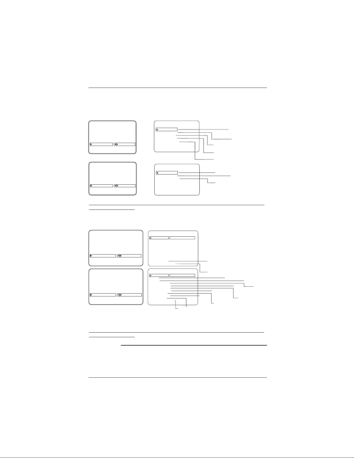
Analog Closed Captions/Text Operating Modes Setup
On the optional Installer’s remote, use MENU, SELECT, and ADJ (Left/Right) arrows
to choose Closed Captions / Text mode and set up other options for the end user.
Quick/Mute When CC is pressed: End user can only turn Captions On/Off.
(If CC on Mute is On, shows captions when sound is muted.)
(If locked, caption type is retained with Power On/Off.)
Standard When CC is pressed: End user can choose a captions type.
(If locked, type is retained with Power On/Off.)
Press ENTER to remove menus.
Digital Captions Operating Modes Setup
On the optional Installer’s remote, use MENU, SELECT, and ADJ (Left/Right) arrows
to configure the Digital Captions appearance.
Language Selects the default Digital Caption Language.
Style:
Set By Program Captions appear white text on black, similar to analog captions.
Custom The installer configures the Digital Captions appearance, see the
next page for the digital captions appearance options available.
Press ENTER to remove menus.
Captions: Analog-Digital (Caption/Text) Setup Overview
Standard closed captioning is available using the Caption 1 option.
Caption/Text are features which allow the TV to display the closed caption and/or text options if
made available by the broadcaster.
Availability and functionality of Caption/Text options are determined only by each broadcaster and
may not be available on every program.
Set up Closed Caption/Text options for the end user
Analog-Digital Closed Captions/Text Overview, End-user Setup
The caption/text feature is designed to be available to the end user on either an
analog or digital channel. For the end user to get analog captions, all the user
needs to do is press CC on the remote and select On - - same for digital channels,
select On and pick a language. The installer can elect to make analog and digital
captions available by turning captions on. The installer sets the caption options
on both analog and digital menus. To set up digital captions, the installer must
tune in a channel with digital captions. Use ‘Set by Program’ to show digital cap-
tions that are similar in appearance to analog captions e.g. white text on black.
End User Captions Operation
If both analog and digital captions are turned on by the installer, analog and digi-
tal captions will be available to the end user. If digital captions are not available
on a digital channel and analog captions are, then analog captions will appear.
Page 31
Page 32
Mini Glossary
CAPTIONS The term for the words that scroll across the bottom of your TV screen; usually the audio
portion of the program provided for the hearing impaired.
TEXT The term for the words that appear in a large black frame and almost cover the entire
screen; usually messages provided by the broadcaster. (Only available on analog channels.)
AUTO PROGRAM
ADD/DEL/BLNK
CH. LABELS
SOURCE NAME
CLOCK SET
TIMER
CAPTIONS
LANGUAGE
TO SET CAPTIONS
SETUP MENU
OPER. MODE
SEL. CC TYPE
CC CAPTION
CC ON MUTE
CAPTION LOCK
CAPTION 1
CAPTION 2
CAPTION 3
CAPTION 4
TEXT 1
TEXT 2
TEXT 3
TEXT 4
QUICK MUTE
ON/OFF
AUTO PROGRAM
ADD/DEL/BLNK
CH. LABELS
SOURCE NAME
CLOCK SET
TIMER
CAPTIONS
LANGUAGE
TO SET CAPTIONS
SETUP MENU
OPER. MODE
SEL. CC TYPE
CAPTION LOCK
CAPTION SETUP
CAPTION SETUP
CAPTION 1
CAPTION 2
CAPTION 3
CAPTION 4
TEXT 1
TEXT 2
TEXT 3
TEXT 4
STANDARD
ON/OFF
NOT AVAILABLE
ON/OFF
AUTO PROGRAM
ADD/DEL/BLNK
CH. LABELS
SOURCE NAME
CLOCK SET
TIMER
CAPTIONS
LANGUAGE
TO SET CAPTIONS
SETUP MENU
AUTO PROGRAM
ADD/DEL/BLNK
CH. LABELS
SOURCE NAME
CLOCK SET
TIMER
CAPTIONS
LANGUAGE
TO SET CAPTIONS
SETUP MENU
STYLE
SIZE
FONT
TEXT COLOR
TEXT OPACITY
BACK COLOR
BACK OPACITY
EDGE TYPE
EDGE COLOR
SERVICE
CAPTION LOCK
STYLE
SIZE
FONT
TEXT COLOR
TEXT OPACITY
BACK COLOR
BACK OPACITY
EDGE TYPE
EDGE COLOR
SERVICE
CAPTION LOCK
ON
OFF
BLACK
WHITE
RED
GREEN
BLUE
YELLOW
MAGENTA
CYAN
SOLID
FLASH
TRANSLUCENT
TRANSPARENT
SOLID
FLASH
TRANSLUCENT
TRANSPARENT
BLACK
WHITE
RED
GREEN
BLUE
YELLOW
MAGENTA
CYAN
BLACK
WHITE
RED
GREEN
BLUE
YELLOW
MAGENTA
CYAN
NONE
RAISED
DEPRESSED
UNIFORM
LEFT SHADOW
RIGHT SHADOW
ON
OFF
CAPTION 4
CAPTION 5
CAPTION 6
DIGITAL CAPTIONS SETUP
DIGITAL CAPTIONS SETUP
SET BY PROGRAM
CUSTOM
Availability and functionality of Digital Captions are determined only by each broadcaster and may not be
available on every program.
Captions: Analog-Digital Menu Structures
Review Analog and Digital Captions options available
Note: Digital captions are only available on some digital channels.
Digital Captions Menu Structure
Analog Captions Menu Structure
Availability and functionality of Analog Captions are determined only by each broadcaster and may not be
available on every program.
OFF
CAPTION 1
CAPTION 2
CAPTION 3
OFF
CAPTION 1
CAPTION 2
CAPTION 3
CAPTION 4
CAPTION 5
CAPTION 6
STANDARD
NORMAL
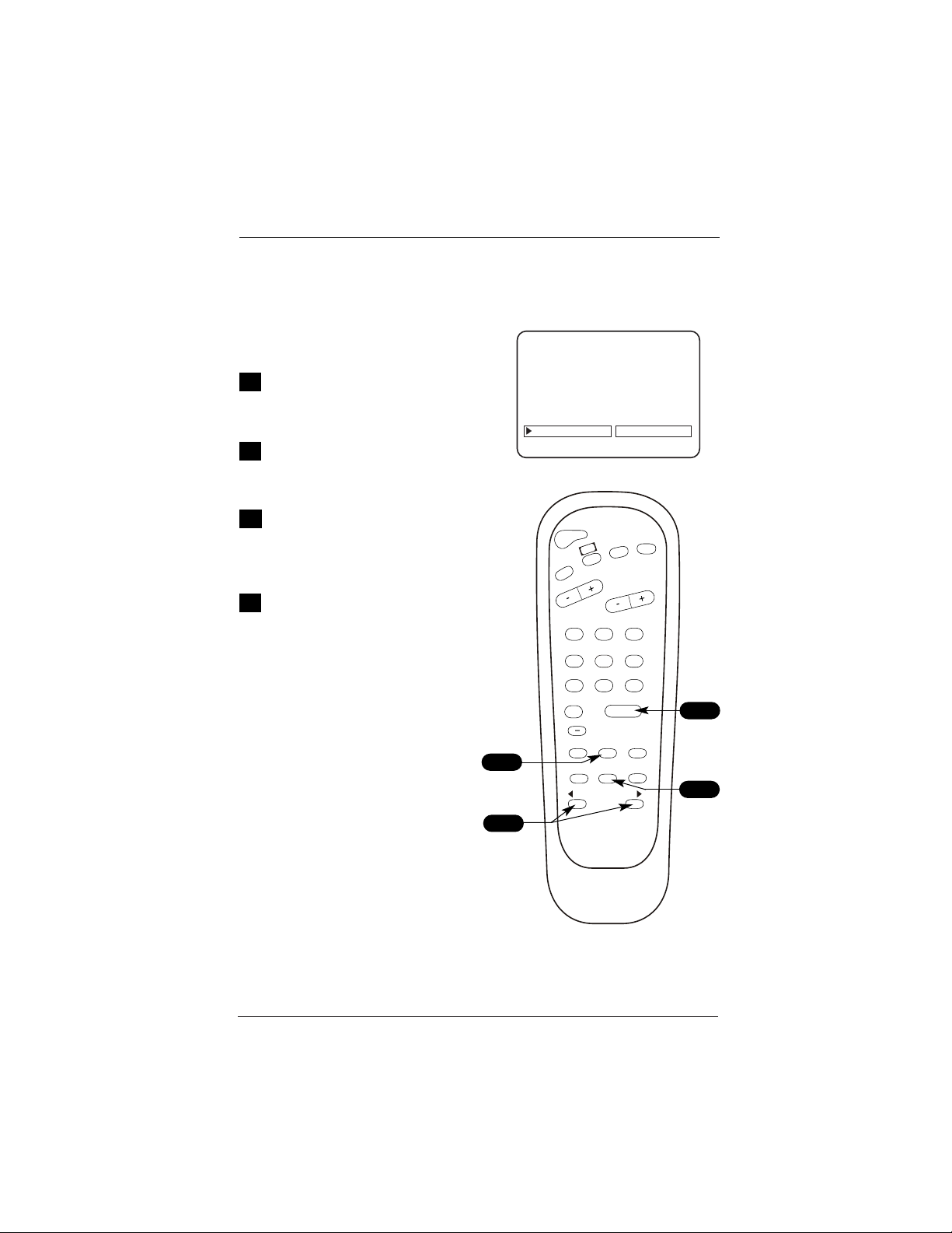
Page 33
On the optional Installer’s remote,
press MENU repeatedly until the
Setup menu appears.
Use SELECT on the remote control,
to highlight the Language option
on the menu.
Use the Left/Right ADJ arrow to
choose one of the following
options: English, Spanish (Español)
or French (Francais).
Press ENTER to remove menu.
Language for the On-Screen Menus
Choose English, Spanish, (Español) or French (Francais)
for the on-screen menus
1
2
3
4
SETUP MENU
AUTO PROGRAM
ADD/DEL/BLNK
CH. LABELS
SOURCE NAME
CLOCK SET
TIMER
CAPTIONS
LANGUAGE
POWER
FLSHBK
MUTE
CC
CHANNEL
VOLUME
ENTER
0
9
87
6
5
4
3
2
1
ALARM
CH PREVIEW
AUDIO
TIMER
MENU
SELECT
ADJ
ADJ
TV/FM
1
2
3
4
ENGLISH
Page 34
On the optional Installer’s remote, press
MENU repeatedly to go to the Audio menu.
Using SELECT on the remote control, high-
light the audio menu option you want to
change. Choose from:
• Bass: Increases/decreases lower-end
sounds.
• Treble: Increases/decreases higher-end
sounds.
• Balance: Allows you to put the sound
more to the left or right channel.
• Audio Mode: Choose from Stereo sound,
Mono, or 2nd Audio/SAP.
• Audio Lang: Choose from English,
Spanish or French Audio Language default.
(Only available on Digital Channels.)
• Front Surround: Turns front surround
speakers on and off.
• SoundRite: Turns the uniform volume fea-
ture on and off.
• Audio Pref: Selects Custom or Preset.
Use the Left/Right ADJ arrow to adjust or
change the option you have selected.
Use SELECT to choose other Audio menu
options, or press ENTER to remove menu.
Use the Audio button to scan the Audio
Languages available for a Digital Channel.
Not all programming is broadcast in stereo
sound or has 2nd Audio SAP.
Not all Digital Channels offer more than
one audio language. (See the next page.)
The audio language selected must actually
contain audio so that it can be heard by
the end user.
Audio Menu
Set up the audio menu options for the end user
1
2
3
4
5
BASS
TREBLE
BALANCE
AUDIO MODE
FRONT SURROUND
SOUNDRITE
AUTO PREF
AUDIO MENU
STEREO
OFF
OFF
CUSTOM
Analog Channel Display
BASS
TREBLE
BALANCE
AUDIO LANG
FRONT SURROUND
SOUNDRITE
AUTO PREF
AUDIO MENU
ENGLISH
OFF
OFF
CUSTOM
Digital Channel Display
ENTER
0
9
87
6
5
4
3
2
1
ALARM
CH PREVIEW
AUDIO
TIMER
MENU
SELECT
ADJ
ADJ
2
4
1
3
5
Page 35
Mini Glossary
STEREO SOUND Stereo (stereophonic) sound refers to audio that’s divided into right and left sides.
MONO SOUND Mono (monaural) sound is one channel of sound. On more than one speaker, all
the speakers play the same audio.
CUSTOM Your own audio menu settings.
PRESET Resets audio menu values to their original settings.
Audio Menu: Digital Audio Language Selection
Use the AUDIO button to select digital audio languages, if available
Indicates the broadcast has additional
audio languages available.
Note: The broadcaster has control of
any additional languages available. If
a program display shows another lan-
guage is being broadcast, press the
AUDIO button to select that audio. If
however, no other language is being
included on the program’s signal, no
other audio may be heard. This con-
dition is not the fault of the TV. If no
other language is being broadcast, the
TV can’t play it. To hear audio, you
must select an active language.
On the optional Installer’s remote,
press AUDIO repeatedly to scroll the
available digital audio language on
the selected channel.
• As mentioned above, even if anoth-
er language is indicated as being
available, if it is not being added to
the audio signal, no audio will be
heard for that additional language.
1
POWER
FLSHBK
MUTE
CC
CHANNEL
VOLUME
ENTER
0
9
87
6
5
4
3
2
1
ALARM
CH PREVIEW
AUDIO
TIMER
MENU
SELECT
ADJ
ADJ
TV/FM
1
News and local programming 5:50 PM
Thu Jan 19, 2007 4:00 PM 6:00 PM
DTV 66-1
Dolby Digital HD
Multi-lingual 16:9 1080i TV-PG

Page 36
On the optional installer’s remote, press the
MENU key repeatedly until the Video menu
appears. Your options are:
• Contrast: Adjusts the level of difference
between white and black in the TV picture.
The more contrast, the brighter the picture
appears.
• Brightness: Increases or decreases amount
of white in the TV picture.
• Color: Adjusts levels of all colors in the
TV picture.
• Tint: Adjusts the relative amounts of red
and green in the picture.
• Sharpness: Raises or lowers the definition
of the picture. The lower the level, the soft-
er the image will appear.
• Aspect Ratio: (Digital channels) Modifies
height and width ratio of the picture when
available from the broadcaster. Aspect Ratio
options: Zoom, Full Screen, Letter box.
• Picture Preference: Choose either Custom
or Preset:
Custom = Allows you to set the picture
appearance to your requirements.
Preset = Resets all the above options back
to their original, factory-set levels.
Using SELECT on the remote control, choose
Contrast on the menu.
Use the Left/Right ADJ arrow to change or
adjust the contrast level as required.
Press ENTER, to remove the menu, or repeat
from Step 2 to adjust other Video menu
options.
Choose the Preset option in Picture Preference to quickly
reset the Video menu options to their original default
values.
Aspect Ratio is only for Digital Channels. The availability
of Aspect Ratios are determined only by the broadcaster
and may not be available on all programs.
Aspect Ratio options are not available for 480i (SD) dig-
ital channels.
Video Menu
Use the Video Menu to customize the picture’s appearance
1
2
3
4
CONTRAST
BRIGHTNESS
COLOR
TINT
SHARPNESS
PICTURE PREF
VIDEO MENU
CUSTOM
Analog Channel Display
Digital Channel Display
CONTRAST
BRIGHTNESS
COLOR
TINT
SHARPNESS
ASPECT RATIO
PICTURE PREF
VIDEO MENU
LETTER BOX
CUSTOM
ENTER
0
9
87
6
5
4
3
2
1
ALARM
CH PREVIEW
AUDIO
TIMER
MENU
SELECT
ADJ
ADJ
2
4
1
3

Page 37
Overview
Parental Control offers the user a wide variety of options and settings that restrict
or “block” the programming that can appear on the TV. Parental Control allows the
user the capability of defining which program rating they consider acceptable, to
the younger or more sensitive viewer. It can be preset and turned either on or off
by the user who specifies a secret 4-number code, the password. The number of
hours blocked are specified. General audience and children viewer blocks can both
be programmed into the TV’s memory. Viewer ratings are specified for both TV and
the motion picture industry; both rating systems should be used, for complete cov-
erage. The ratings are based on the ages of children. (See following pages.)
To insure complete coverage for all TV programs, (movies and regular TV shows)
choose a rating for MPAA to restrict movies from the selections on the following
pages. AND choose ratings from the TV Parental Guidelines Rating System also on
the following pages, using the Age Block option for General Audiences and for
Children. In addition to those, you may wish to add additional restrictions from
the Content Block sub menu. See the Parental Control menu and submenus exam-
ples on the following pages.
Things to Consider before Setting Up Parental Control
• Determine which rating you consider acceptable to the viewer. For example, if
you choose TV-PG, all more restrictive ratings will be automatically blocked; the
viewer will not be able to see: TV-PG, TV-14 or TV-MA rated programming.
• Do you want to block the auxiliary video source entirely? (Blocks the signal sent
by the equipment, such as a VCR, connected to the TV Audio/Video input jacks;
in the Aux. Sources option.) Or leave unblocked, then choose allowable ratings.
• Block program “Content” based on individual parameters such as: Strong Dialog,
Bad Language, Sex Scenes, Violence Scenes or Fantasy Violence Scenes; in the
Content Blk option.
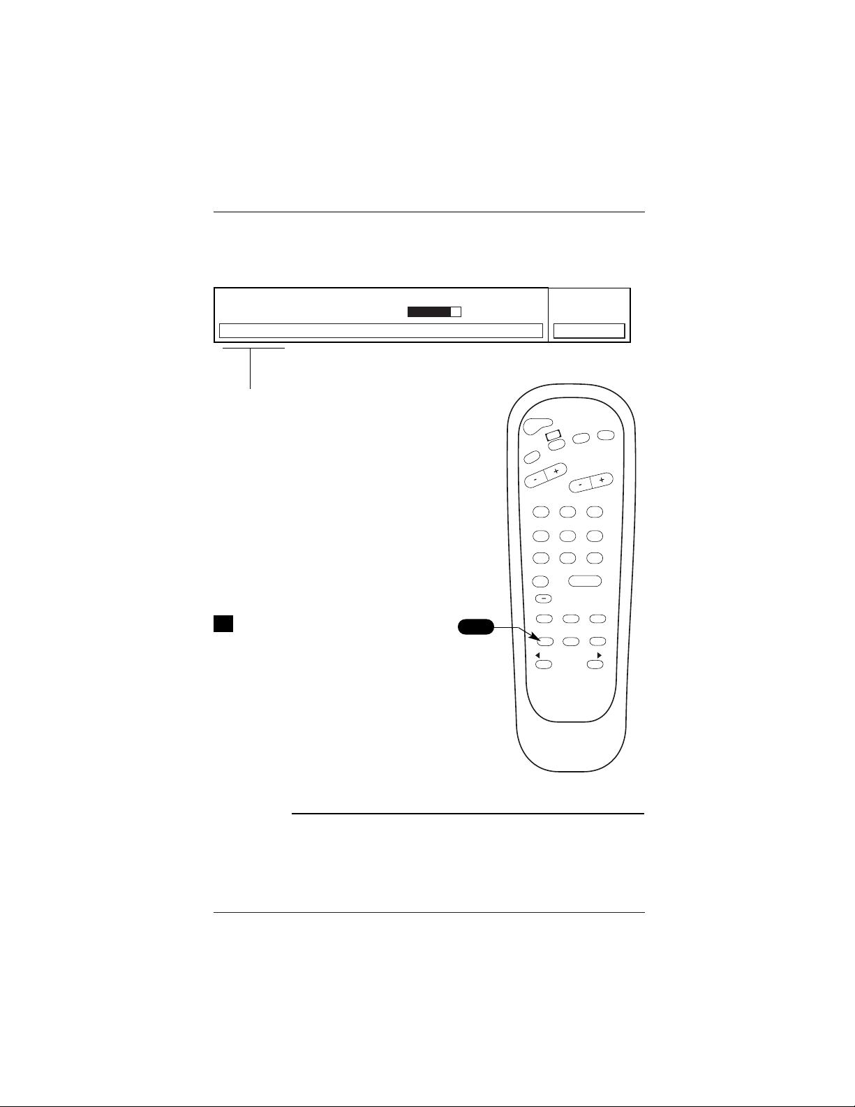
• How many hours do you want Parental Control to be active? You can set the
Hours option for up to 99 hours.
• Select a password; in the Set Password option. Use the numbered keys on the
remote to set a password. Don’t forget the password.
Note: Reset Parental Control Block Hours to Zero and Cancel Password
This provides the institution staff and the installer a means to reset the TV to normal opera-
tion; if a user has either forgotten the password or has left Parental Control Block active.
Note: Installer Menu item 0-I Installer Seq must be set to 0 for this to work.
On the optional installer’s remote control, press and hold down MENU until the menu disap-
pears (takes about 8 seconds). Immediately press 9, 8, 7, 6 and then CC. This will reset the
Block Hours to Zero and cancel the current 4-number password.
Parental Control Menu
This feature can “block” undesirable programming from appearing on the TV.
Set restrictions using Age Block for all programming, TV and movies.
End user can only set restrictions using Ch Preview menu on any Analog channel or
Aux source (some models digital too. The TV will employ parental control restrictions
on analog and digital channels if there is V-Chip data on the program.
Page 38
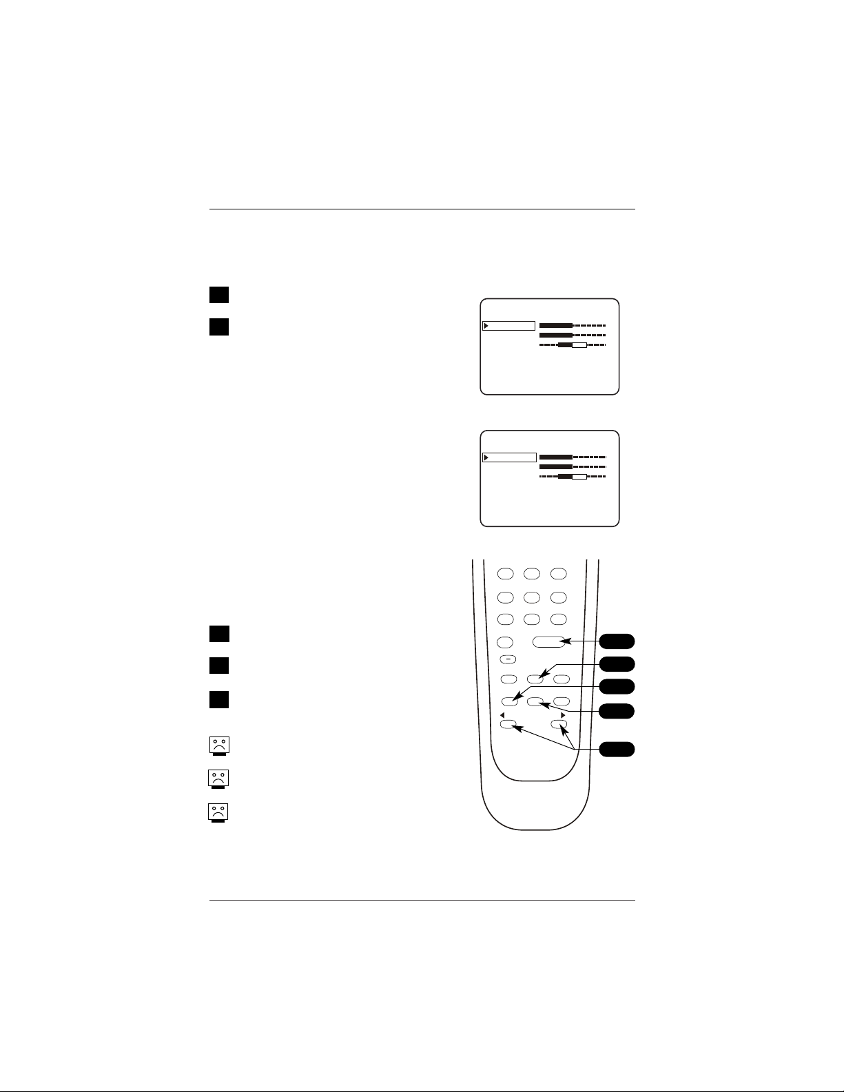
Parental Control Menu
After you have read the preceding page, follow instructions below to set up
and activate Parental Control
As shown above with the Parental Control
menu on-screen, use SELECT to highlight an
option like Age Block for TV programs and
movies, then press the Right ADJ arrow.
Use SELECT, and the Left/Right ADJ arrows
to select and adjust or set the rating for an
option. For Sex Scenes for example, use the
“From TV-PG” setting.
(See the Parental Ratings Charts on the
next page for TV/Movie rating definitions).
After you have selected and adjusted the
parental control menu options to your
requirements:
- Set the hours you want Parental Control
active.
- Set a 4-number password.
- Set the Lock On/Off option to On or Off.
No Rating means that the broadcast does
not include rating information. You can
choose to block broadcasts without rating
data.
1
2
3
4
SOURCE MENU
SETUP MENU
AUDIO MENU
DIALOG
LANGUAGE
SEX SCENES
VIOLENCE
F VIOLENCE
NO RATING
TO BLOCK
GENERAL
CHILDREN
AGE BLOCK
UNBLOCKED
CONTENT BLOCK
TO BLOCK
AUX SOURCES
MPAA RATING
AGE BLOCK
CONTENT BLK
SET HOURS
SET PASSWORD
LOCK ON OFF
PARENTAL CONTROL
VIDEO MENU
PRESS CC TO RETURN
PRESS CC TO RETURN
UNBLOCKED
ENTER
0
9
87
6
5
4
3
2
1
ALARM
CH PREVIEW
AUDIO
TIMER
MENU
SELECT
ADJ
ADJ
2
1
3

Page 39
Parental Control TV/Movie Rating Guidelines
TV Parental Guidelines Rating System
TV-G General Audience Considered suitable for all audiences; children may
watch unattended.
TV-PG Parental Guidance Unsuitable for younger children, may contain:
Suggested Suggestive Dialog, Foul Language, Sex and Violence
Scenes.
TV-14 Parents Strongly Unsuitable for children under 14, may contain:
Cautioned Strong Dialog, Foul Language, Sex and Violence
Scenes.
TV-MA Mature Audiences Adults only, may contain: Strong Dialog, Foul
Only Language, Sex and Violence Scenes.
CHILDREN’S CLASSIFICATIONS
TV-Y Children Considered suitable for all children under 7 years old.
TV-Y7 Children 7 Considered suitable for children over 7, may contain
and over Fantasy Violence Scenes.
Motion Picture Association Of America (MPAA) Rating System
G General Audiences Content not offensive to most viewers.
PG Parental Guidance Content is such that parents may not want their
Suggested children to view the program.
PG-13 Parental Guidance Program is inappropriate for preteens, with a greater
Suggested degree of offensive material than a PG rated program.
R Restricted viewing Not for children under age 17. Strong elements of sex
and/or violence.
NC-17 Restricted Viewing Not for children under age 17 under any
circumstances. Strong sexual content.
X Hard Core Films Same as NC-17 rating.
Note: LG Electronics Corporation is not liable for any program content that appears
when using this rating system; as always, user discretion is advised.
You can set different Parental Control viewing
restrictions for general audiences and for chil-
dren - - both can be active at the same time.
Simply specifying one TV program content
block such as Sex Scenes, will not automati-
cally block another undesirable content in the
TV program from appearing.
Even if you choose to leave the Aux Sources
unblocked, the ratings you specify will auto-
matically restrict the programming from the
video sources.
You cannot disable Parental Control by discon-
necting the TV from power. Block hours will
automatically reset to original block time set-
ting specified if power is disconnected.
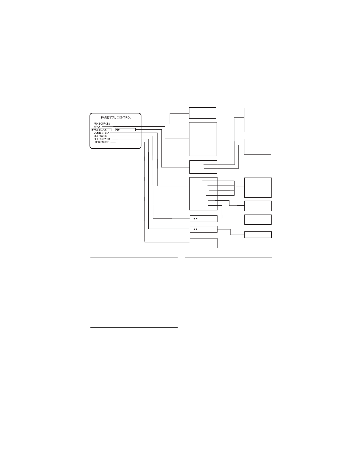
Page 40
Parental Control Menu Structure/V-Chip Installer Setups
Note: Reset Parental Control Block
Hours to Zero and Cancel Password
This provides the institution staff and the installer
a means to reset the TV to normal operation; if a
user has either forgotten the password or has left
Parental Control Block active.
On the optional installer’s remote control, press
and hold down MENU until the menu disappears
(takes about 8 seconds). Immediately press 9, 8,
7, 6 and then CC. This will reset the Block Hours
to Zero and cancel the current 4-number password.
Make Parental Control restrictions
permanent, with no preset or fixed
hours time limit
In the Installer’s Menu, set
Item 84: PERMANENT BLK, 0 or 1.
0 Blocking restrictions always active, no time limit.
1 Restrictions limited to specified hours, 12 - 99.
Reset the Maximum Number of
Parental Control Default Block Hours
You can change the Block hours from the 12-hour
default setting to up to 99 hours.
In the Installer’s Menu, item: 22-I MAX BLK HRS
12, use the ADJ Left/Right adjust arrow to set a
different default number of hours.
Turn Parental Control Feature Off/On
In the Installer’s Menu, installer items:
21-I V-CHIP, 0 = disable, or 1 = enable
51-I DIS. VCHIP M., 0 = enable, or 1 = disable
Options Setups for V-Chip Menu and
Block Functions
For Installer items: 21-I V-CHIP, 51-I DIS VCHIP M
0 0 No menu, no blocking.
0 1 No menu, no blocking.
1 0 Shows menu, Block functions.
1 1 No menu, Block functions.
Unblocked
Blocked
General
Children
Unblocked
G and Above
PG and Above
PG-13 and Above
R and Above
NC-17 and Above
X
Dialog
Language
Sex Scenes
Violence
F Violence
No Rating
TO BLOCK
Unblocked
TV-PG and Above
TV-14 and Above
TV-MA
Unblocked
TV-Y7
Unblocked
Blocked
Unblocked
TV-G and Above
TV-PG and Above
TV-14 and Above
TV-MA
Unblocked
TV-Y and Above
TV-Y7
00 Hours
To Set
Enter Code: - - - -
On
Off
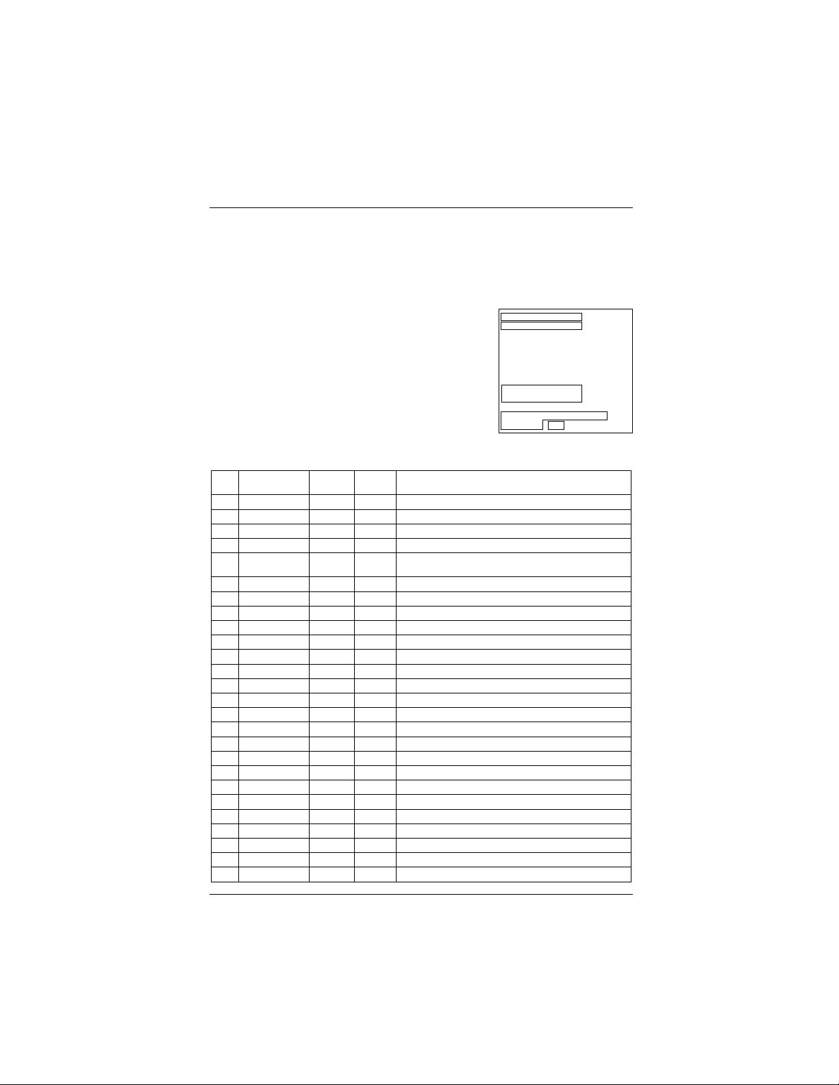
Installer’s menu items can be
accessed by using the optional
installer’s remote control. Just
press and hold MENU (about 8
seconds) until the menu disap-
pears, then press 9, 8, 7, 6,
then ENTER. To remove the
Installer’s Menu, press ENTER
repeatedly. Any changes you
make will be stored in non-
volatile memory.
The Installer’s menu opens with
the main menu. Use MENU and
SELECT to sequence through the
installer menus and submenus.
Use SELECT or TV/FM to scroll
up/down in the menus and sub-
menus. To change a setting use
the Left/Right ADJ keys. Press
ENTER to return to main menu.
Using the Installer’s Menu
Items 0-I - 103-I are accessible
only in the Installer’s Menu.
Their numbers, descriptions,
ranges, factory default settings,
and a place for listing any
changes made on site are given
below and on the following
pages.
The Factory Menu that is intend-
ed for qualified service techni-
cians only, is not shown. XX-F
Menu Items (not shown here)
are service type adjustments and
only qualified technicians hav-
ing specialized test equipment
should access them.
INSTALLERS
INSTALLERS1
INSTALLERS2
INSTALLERS3
INSTALLERS4
INSTALLERS5
INSTALLERS6
INSTALLERS7
INSTALLERS8
MICRO V3.00
D2A CARD - MICRO COMM
STATUS OK
Typical Installer Menu
Menu Function Value Default Brief Description of Function and Comments
Item Range Value
0-I. INSTALLER SEQ 0 - 3 0 Leave default set at 0.
1-I. POWER MANAGE 0 - 7 0 Sets number of hours of no activity before auto shutoff.
2-I. AC ON 0 / 1 0 Set to 1 to enable auto turn on at power up.
3-I. BAND-AFC 0 - 7 0 Sets Tuning band.
4-I. STRT CHANNEL 0 - 255 255 Channel at turn-on (255 for last Channel). For digital
channels, use with item 101-I Start Minor Channel.
5-I. CHAN LOCK 0 / 1 0 When set to 1, cannot tune from current channel.
6-I. GHOST CH 0 / 1 0 Set to 1 to enable Ghost Channel display.
7-I. START VOLUME 0-63, 255 255 Volume level at TV turn-on (Set 255 to retain last level).
8-I. MIN VOLUME 0 - 63 0 Minimum volume setting.
9-I. MAX VOLUME 0 - 63 63 Maximum volume setting.
10-I. MUTE DISABLE 0 / 1 0 Set to 1 to disable mute function.
11-I. KEY DEFEAT 0/ 1 1 Set to 1 to disable the front panel keyboard MENU key.
12-I. NOT USED
13-I. SCAN MODE 0 / 1 0 Puts TV On-Off event in Ch Up/Down sequence.
14-I. NOT USED
15-I. SLEEP TIMER 0 / 1 1 Set to 1 to enable Sleep Timer.
16-I. EN TIMER 0 / 1 1 Set to 1 to enable Timer.
17-I. ALARM 0 / 1 1 Set to 1 to enable Alarm.
18-I. NOT USED
19-I. NOT USED
20-I. FEATURE LEVEL 0 / 1 1 Zen 1 Leave default set 1 (1 Zen1).
21-I. V-CHIP 0 / 1 1 Set to 1 to enable V-Chip (Parental Control).
22-I. MAX BLK HRS 0 - 99 12 Sets number of Parental Control blocking hours.
23-I. CAPTION LOCK 0 / 1 0 Set to 1 to retain caption setting at turn off.
24-I. TEXT MODE 0 / 1 1 Set to 1 to add Text option to closed caption menu.
25-I. FUNCTION PRE. 0 - 3 0 Controls channel preview in Pay-Per-View function menu.
Installer Menu
Use the Installer Menu to set up or change operational settings.
See detailed descriptions of the Installer Menu items on the following pages
Page 41
D2A CARD V3.00

Menu Function Value Default Brief Description of Function and Comments
Item Range Value
26-I. NOT USED
27-I. NOT USED
28-I. CH OVER RIDE 0 / 1 1 When set to 0, limits direct access to favorite channels.
29-I. OLD OCV 0 / 1 0 OCV should set to 1.
30-I. ACK MASK 0 / 1 0 M.P.I. communication parameter.
31-I. POLL RATE 20 - 169 94 M.P.I. communication parameter.
32-I. TIMING PULSE 186 - 227 204 M.P.I . communication parameter.
33-I. NOT USED
34-I. CAMPORT EN 0 / 1 1 Set to 1 to enable the front AUX (Camport ) input.
35-I. SUP. PORT YUV 0 / 1 0 Reserved for future use.
36-I. FRNT Y-C EN 0 / 1 1 Set to 1 to enable the front S-Video input.
37-I. NOT USED
38-I. YPRPB EN 0 / 1 1 Set to 1 to enable the component input.
39-I. REAR VIDEO EN 0 / 1 1 Set to 1 to enable rear AUX video input.
40-I. AUTO CAMPORT 0 / 1 1 Set to 1 to automatically switch to Camport.
41-I. NOT USED
42-I. AUTO FRNT Y-C 0 / 1 1 Set to 1 to automatically switch to front S-Video input.
43-I. NOT USED
44-I. NOT USED
45-I. NOT USED
46-I. STRT AUX SRCE 0-2, 255 255 Sets the starting AUX source.
47-I. AUX STATUS 0 / 1 0 Set to 1 for M.P.I. AUX source reported as Channel
number instead of Channel 0.
48-I. DIS SETUP M 0 / 1 0 Set to 1 to disable Setup menu.
49-I. DIS AUDIO M 0 / 1 0 Set to 1 to disable Audio menu.
50-I. DIS VIDEO M 0 / 1 0 Set to 1 to disable Video menu.
51-I. DIS VCHIP M 0 / 1 0 Set to 1 to disable V-Chip (Parental Control) menu.
52-I. DIS SOURCE M 0 / 1 0 Set to 1 to disable Source menu.
53-I. DIS CHTIME M 0 / 1 0 Set to 1 to disable Channel-Time on-screen display.
54-I. EN SET COL 0 / 1 0 Set to 1 to enable custom color for the Setup menu.
55-I. FOR SETUP M 0 - 7 6 Custom foreground color for the Setup menu.
56-I. BCK SETUP M 0 - 7 4 Custom background color for the Setup menu.
57-I. EN AUDIO COL 0 / 1 0 Set to 1 to enable custom color for the Audio menu.
60-I. EN VIDEO COL 0 / 1 0 Set to 1 to enable custom color for the Video menu.
61-I. FOR VIDEO M 0 - 7 4 Custom foreground color for the Video menu.
62-I. BCK VIDEO M 0 - 7 7 Custom background color for the Video menu.
63-I. EN PTL COL 0 / 1 0 Set to 1 to enable custom color for the V-Chip
(Parental Control) menu.
Page 42
Installer Menu
Installer Menu Items 26-I through 63-I
58-I. FOR AUDIO M 0 - 7 1 Custom foreground color for the Audio menu.
59-I. BCK AUDIO M 0 - 7 7 Custom background color for the Audio menu.

Page 43
Menu Function Value Default Brief Description of Function and Comments
Item Range Value
64-I. FOR PTL M 0 - 7 6 Custom foreground color for the V-Chip
(Parental Control) menu.
65-I. BCK PTL M 0 - 7 4 Custom background color for the V-Chip
(Parental Control) menu.
66-I. EN SRC COL 0 / 1 0 Set to 1 to enable custom color for the Source menu.
67-I. FOR SRC M 0 / 7 3 Custom foreground color for the Source menu.
68-I. BCK SRC M 0 - 7 4 Custom background color for the Source menu.
69-I. EN CHT COL 0 / 1 1 Set to 1 to enable custom color for the
Channel-Time on-screen display.
70-I. FOR CHT COL 0 - 7 1 Custom foreground color for the Channel-Time display.
71-I. BCK CHT COL 0 - 7 1 Custom background color for the Channel-Time display.
72-I. NOT USED
73-I. CH NOT AVBLE 0 / 1 0 When set to 1 and channel over ride is set to 0,
“NOT AVAILABLE” message is displayed when directly
accessing a channel not in the favorite channel list.
74-I. CH-TIME SIZE 0 / 1 0 When set to 1 and transparent background is selected
for Channel-Time display, (foreground color =
background color and custom color enabled) a large
channel number is displayed instead of the normal
Channel-Time on-screen display.
75-I. REVERT CH 0 / 1 0 When set to 1 and loss of M.P.I. communication occurs,
TV tunes to Start Channel.
76-I. DEFEAT XDS 0 / 1 0 When set to 1, XDS display program information
will not appear.
77-I. NOT USED
78-I. UPN MSB 0 - 255 (*) User programmable number, most significant byte.
79-I. UPN MSB1 0 - 255 (*) User programmable number, most significant byte- 1.
80-I. UPN MSB2 0 - 255 (*) User programmable number, most significant byte- 2.
81-I. UPN LSB 0 - 255 (*) User programmable number, least significant byte.
82-I. CHKSM ERROR 0 / 1 1 Enforces rigid M.P.I. checksum.
83-I. HANDSHK TIME 0 - 5 0 Relaxes M.P.I. timing to be compatible with
PC based Windows controlled systems.
84-I. PERMANENT BLK 0 / 1 0 Removes block hours setting for Parental Control
and make blocks permanent.
85-I. A MUTE TIME 0 - 254 35 Controls muting audio delay time when switching
between AUX sources.
86-I. V MUTE TIME 0 - 254 40 Controls muting video delay time when switching
between AUX sources.
87-I. NOT USED
88-I. EN NOISE MUTE 0 / 1 1 When set to 1, the audio signal volume is limited to
a minimum value if no signal is being received from
the broadcaster.
Installer Menu
Installer Menu Items 64-I through 88-I
(*) Note: These registers are programmed at factory with initial values and user can modify them at any time.

Menu Function Value Default Brief Description of Function and Comments
Item Range Value
89-I. POKE ENABLE 0 / 1 0 If set to 1, writing to Non - volatile memory
through *M.P.I. is enabled.
90-I. KEY LOCK 0 / 1 0 If set to 1, front keyboard functionality is disabled.
91-I. NOT USED
92-I. NOT USED
93-I. NOT USED
94-I. NOT USED
95-I. AUDIO MD DISP 0 / 1 1 1: Audio Mode information appears in the ch time display
96-I. NOT USED
97-I. NOT USED
98-I. NOT USED
99-I. NOT USED
100-I. NOT USED
101-I. NOT USED
102-I. ATSC BAND 0 - 4 4 Sets digital tuning band.
103-I. ATSC TUNE MD 0 / 1 1 Sets ATSC tuning mode. 0:virtual channel, 1:physical channel
104-I STRT MINOR CH 0 - 255 0 Selects Minor start channel. Set 0 for NTSC.
Not 0, sets Minor channel number.
105-I NOT USED
106-I A RATIO LOCK 0 / 1 0 To retain set aspect ratio on power cycle, set to 1.
Set to 0 for default ratio on power cycle.
107-I NOT USED
108-I NOT USED
109-I NOT USED
110-I NOT USED
111-I NOT USED
112-I NOT USED
113-I NOT USED
114-I NOT USED
115-I NOT USED
116-I NOT USED
117-I RESET2DEFAULT 0 / 1 0 0=Normal. 1=Loads factory default presets
Installer Menu
Installer Menu Items 89-I through 117-I
Page 44
for all above settings.

Installer Menu
Detailed Descriptions of Installer Menu Items
0-I. INSTALLER SEQUENCE
Gives access to Installer Menu depending on
the code selected.
0 = 9876 1 = 4321
2 = 1478 3 = 3698
1-I. POWER MANAGE (Power Management)
Determines hours of no activity before automatic
shutoff. The POWER MANAGE function is for
saving energy. When set to 0, Power Manage
is OFF.
Settings range from 0 - 7, with 1 - 7 representing
the hours that the TV will remain on, unless there
has been activity from either the control panel or
remote control.
*M.P.I. Multiple Protocol Input: LG protocol for
remote control of TV through RJ11 (M.P.I.) jack
on TV connections panel.
2-I. AC ON (AC Power Switchable)
Allows the TV to turn ON just by applying AC
power. Pressing the ON button is not necessary.
This is desirable when the TV is plugged into a
cablebox or a power outlet controlled by a
wallswitch. UseADJ to select 0 or 1, where 0 is
the default is OFF, and1 is ON.
NOTE: When set to 1 (ON), the TV does notrespond
to ON/OFF commands from either the remoteorthe
control panel, and the SLEEP TIMER is also not
functional.
3-I. BAND/AFC (Band/Automatic
Frequency Control)
There are 8 possible settings for this option:
0 = Broadcast Fixed 4 = Broadcast AFC
5 = CATV Fixed 1 = CATV AFC
6 = HRC Fixed 2 = HRC AFC
7 = ICC Fixed 3 = ICC AFC
Channels are accessed faster when fixed modes.
are used.The AFC (search modes) should only be
used when some channels are not on nominal
frequencies.
NOTE:
BAND is automatically set by AUTOPROGRAM .
If some channels were not found by AUTO-
PROGRAM, select the appropriate AFC setting
here and add the channels using the ADD/DEL
option in the Setup Menu.
Page 45

Page 46
4-I. STRT CHANNEL (Start Channel)
Important: For NTSC start channel, item
104-I STRT MINOR CHANNEL, must be set to
0. When active, this function allows you to
determine the initial channel number when the TV
is turned ON. (To set a digital channel, use with
Item 104-I Start Minor Channel). This feature is use-
ful for an in-house information channel, since the
TV would always select that channel when it is
turned on. Setting this to 255 causes the last
channel viewed when TV was turned off to be the
tuned to channel when the TV is turned on again.
The range of values is 0 - 255. Use ADJ (adjust)
keys to choose numbers for the start channel.
5-I. CHAN LOCK (Channel Lock)
CHAN LOCK is ideal if a cable box (or similar) is
the sole source for programming—and the TV must
always be on the same channel. Changing channels
with Channel Up/Down or keypad numbers is
impossible. Channel Lock is inactive when set to 0
(default). Generally, this feature is used in con-
junction with START CHANNEL (item 4-I.) where
the start channel may, for example, be set to 3 or
4. If the start channel is 3, then the TV will
remain on channel 3.
NOTE: When CHANNEL LOCK is active and CHANNEL
OVER RIDE is disabled, AUTO PROGRAM is not func-
tional.
6-I. GHOST CH (Ghost Channel)
When set to 1, the current channel number is dis-
played in the upper right corner of the picture. The
number moves slightly to prevent damage to the
screen. The default is “0” or OFF. NOTE: When cap-
tions are on, “Ghost Channel” is not displayed.
7-I. START VOLUME
This function allows the Installer to determine the
initial volume level setting when the TV is turned
ON. This feature is useful for an in-house informa-
tion channel, since the TV would always select
that Volume level when it is turned on. The range
of values are 0 - 63, 255. If 255 is selected, the
current volume level will be retained in memory
when the TV is turned off. At TV turn on, Volume
level is automatically set to the previous or last
level.
8-I. MIN VOLUME (Minimum Volume)
This function determines the minimum volume
level allowable with the VOLUME (VOL) Up/Down
control. In this way, for example, someone cannot
set the sound too low to hear. The range is from 0
to 63 change values with ADJ (adjust). The factory
default is 0, which provides full range of volume
control. It may be best to set the same value on
every TV.
NOTE: The minimum volume level cannot have a
value setting higher than in the MAX VOLUME level
(described below).
9-I. MAX VOLUME (Maximum Volume)
This function determines the maximum volume
level allowable with the VOLUME Up/Down control.
In this way, for example, someone cannot set the
sound level high enough to disturb others. The
range is 0 to 63, with 63 as the default which
gives the user the full range of volume control.
Change values with ADJ Left/Right keys. It may be
best to set the same value on every TV.
NOTE: The maximum volume level cannot have a
value setting lower than the MIN VOLUME level
(See item 8 -I).
10-I. MUTE DISABLE
Enables or disables sound mute function. If set to
1, sound cannot be muted. If set to 0, sound can
be muted.
11-I. KEY DEFEAT
Enables or disables the menu key on the front
panel keyboard. Set to 0 to enable, set to 1 to dis-
able. If set to 1, Key lock appears if MENU key on
front panel is pressed.
12-I. NOT USED
13-I. SCAN MODE
Allows variation in the On/Off setup with CHANNEL
Up/Down. You may opt for TV channels only or TV
channels + Off/On with the following settings for
Scan Mode. Scan mode Characteristics:
0 = Channel Up/Down keys Change channels only.
1 = Channel Down below the lowest channel (or
channel up higher than the highest channel) and
the TV turns off.
Installer Menu
Detailed Descriptions for Installer Menu
Items 4-I through 13-I.

Page 47
14-I. NOT USED
15-I. SLEEP TIMER
When set to 1, the Sleep Timer feature is available
to the user (but no message is displayed prior to
turn-off). When set to 0, the Sleep Timer is not
functional.
16-I. EN. TIMER
Set to 1, On/Off Timer functions are available to
end user. Set to 0 to disable Timer functions.
Note: Clock must be set in order to use Timers.
17-I. ALARM
Gives you the option of making the Alarm function
available to the user. Set to 1, Alarm function is
available to user. Set to 0 to disable the Alarm
function. Note: Clock must be set in order to set
the Alarm.
18-I. NOT USED
19-I. NOT USED
20-I. FEATURE LEVEL
Default set to ZEN 1 for Zenith IR remote control
operation. Set O, P LBL for Zenith Private Label IR
remote control operation. WARNING: Do not
change the default value unless you have the prop-
er remote control to operate the TV.
21-I. V-CHIP
Set to 1 to activate V-Chip (Parental Control); have
it available to user to filter or control or restrict
programming content. Set to 0 to turn V-Chip fea-
ture off, not available to user; no programming
restrictions can be set.
22-I. MAX BLK HRS
Set 0 to 99 for the maximum V-Chip (Parental
Control) block hours. Default setup is for 12 block-
ing hours.
23-I. CAPTION LOCK
Set to 1 to restore previous Caption On/Off state
after TV turns off. When set to 0, Captions are
always off, when TV is initially turned on.
24-I. TEXT MODE
Determines whether TEXT 1, TEXT 2, TEXT 3, or
TEXT 4 decoding is enabled when TEXT is turned on
(either from the Setup Menu or directly with CC on
the remote).
TIP: Set Text Mode to 1 only if text is offered in
your video system.
25-I. FUNCTION PRE
Set to 0 to suppress CHANNEL PREVIEW from the
FUNCTION menu with some Pay-Per-View systems.
26-I. NOT USED
27-I. NOT USED
28-I. CH. OVER RIDE (Channel Override)
When set to 1, the user can select channels with
either Channel Up/Down or by direct keypad entry.
When set to 0, only those channels that are
entered for scanning may be selected by direct
keypad entry. Note: If set to 0, Auto Program is
locked; (as shown on Setup menu) channel search
is not available.
29-I. OLD OCV (On Command Video
TM
)
Set to 1 for operation with systems from On
Command Corporation.
30-I. ACK MASK
M.P.I. Communication Parameter. Leave at
default setting unless changed by Pay-Per-View
provider.
31-I. POLL RATE
M.P.I. Communication Parameter. Leave at default
setting unless changed by Pay-Per-View provider.
32-I. TIMING PULSE
M.P.I. Communication Parameter. Leave at default
setting unless changed by Pay-Per-View provider.
33-I. NOT USED
34-I. CAMPORT ENABLE
Set to 1 to enable the front AUX (Camport)
input. Set to 0 to disable front AUX input.
35-I. SUP. PORT YUV
Reserved for future use.
36-I. FRONT Y-C EN.
Set to 1 to enable the front S-Video input.
Set to 0 to disable front S-Video input.
Installer Menu
Detailed Descriptions for Installer Menu Items 14-I through 36-I

Page 48
Installer Menu
Detailed Descriptions for Installer Menu Items 37-I through 59-I
37-I. NOT USED.
38-I. YPrPb EN.
Set to 1 to enable rear Component Video input. Set
to 0 to disable rear Component Video input.
39-I. REAR VIDEO EN.
Set to 1 to enable rear AUX (Video) input.
Set to 0 to disable rear AUX input.
40-I. AUTO CAMPORT
Set to 1 to automatically switch to Camport when
equipment is connected to front Video input. Set
to 0 to disable front Video automatic source selec-
tion. Note: See notes at end of page 20.
41-I. NOT USED
42-I. AUTO FRONT Y-C
Set to 1 to automatically switch viewing source to
front S-Video input if equipment is connected.
Set to 0 to disable front S-Video auto source selec-
tion. Note: See notes at end of page 20.
43-I. NOT USED
44-I. NOT USED
45-I. NOT USED
46-I. STRT AUX SRCE
Sets the starting AUX source.
47-I. AUX STATUS
Set to 1 for M.P.I. AUX source to be reported as a
channel number instead of channel 0. Set to 0 to
disable AUX identification change.
48-I. DIS SETUP M
Set to 1 to disable the Setup menu. Setup menu
will not appear. Set to 0 to enable the Setup
menu.
49-I. DIS AUDIO M
Set to 1 to disable the Audio menu. Audio menu
will not appear. Set to 0 to enable the Audio
menu.
50-I. DIS VIDEO M
Set to 1 to disable the Video menu. Video menu
will not appear. Set to 0 to enable the Video
menu.
51-I. DIS VCHIP M
Set to 1 to disable V-Chip menu. V-Chip menu will
not appear. Set to 0 to enable the V-Chip menu.
52-I. DIS SOURCE M
Set to 1 to disable Source menu. Source menu will
not appear. Set to 0 to enable the Source menu.
53-I. DIS CH-TIME
Set to 1 to disable the Channel-Time display.
Channel-Time display will not appear.
Set to 0 to enable the Channel-Time display.
54-I. EN SET COL
Set to 1 to enable custom color settings for the
Setup menu. Set to 0 to disable custom color set-
tings for the Setup menu.
55-I. FOR SETUP M (Setup Menu Foreground
Color)
Set according to Color Chart.
0 = Black 3 = Yellow 6 = Cyan
1 = Red 4 = Blue 7 = White
2 = Green 5 = Violet
56-I. BCK SETUP M (Setup Menu Background
Color)
0 = Black 3 = Yellow 6 = Cyan
1 = Red 4 = Blue 7 = White
2 = Green 5 = Violet
57-I. EN AUDIO COL
Set to 1 to enable custom color settings for the
Audio menu. Set to 0 to disable custom color set-
tings for the Audio menu.
58-I. FOR AUDIO COL (Audio Menu Foreground
Color)
0 = Black 3 = Yellow 6 = Cyan
1 = Red 4 = Blue 7 = White
2 = Green 5 = Violet
59-I. BCK AUDIO COL (Audio Menu Background
Color)
0 = Black 3 = Yellow 6 = Cyan
1 = Red 4 = Blue 7 = White
2 = Green 5 = Violet

Page 49
Installer Menu
Detailed Descriptions for Installer Menu Items 60-I through 75-I
60-I. EN VIDEO COL
Set to 1 to enable custom color settings for the
Video menu. Set to 0 to disable custom color set-
tings for the Video menu.
61-I. FOR VIDEO M (Video Menu Foreground
Color)
0 = Black 3 = Yellow 6 = Cyan
1 = Red 4 = Blue 7 = White
2 = Green 5 = Violet
62-I. BCK VIDEO COL (Video Menu Background
Color)
0 = Black 3 = Yellow 6 = Cyan
1 = Red 4 = Blue 7 = White
2 = Green 5 = Violet
63-I. EN PTL COL
Set to 1 to enable custom color settings for the V-
Chip menu. Set to 0 to disable custom color set-
tings for the V-Chip menu.
64-I. FOR PTL M (V-Chip Menu Foreground
Color)
0 = Black 3 = Yellow 6 = Cyan
1 = Red 4 = Blue 7 = White
2 = Green 5 = Violet
65-I. BCK PTL M (V-Chip Menu Background
Color)
0 = Black 3 = Yellow 6 = Cyan
1 = Red 4 = Blue 7 = White
2 = Green 5 = Violet
66-I. EN SRC COL
Set to 1 to enable custom color for the Source
menu. Set to 0 to disable custom color for the
Source menu.
67-I. FOR SRC M (Source Menu Foreground
Color)
0 = Black 3 = Yellow 6 = Cyan
1 = Red 4 = Blue 7 = White
2 = Green 5 = Violet
68-I. BCK SRC M (Source Menu Background
Color)
0 = Black 3 = Yellow 6 = Cyan
1 = Red 4 = Blue 7 = White
2 = Green 5 = Violet
69-I. EN CH-T COL
Set to 1 to enable custom color for the Channel-
Time display. Set to 0 to disable custom color for
the Channel-Time display.
70-I. FOR CH-T COL (Channel-Time Display
Foreground Color)
0 = Black 3 = Yellow 6 = Cyan
1 = Red 4 = Blue 7 = White
2 = Green 5 = Violet
Note: If foreground and background color are the
same, menu background is transparent.
71-I. BCK CH-T COL (Channel-Time Display
Background Color)
0 = Black 3 = Yellow 6 = Cyan
1 = Red 4 = Blue 7 = White
2 = Green 5 = Violet
Note: If foreground and background color are the
same, menu background is transparent.
72-I. NOT USED
73-I. CH NOT AVBLE
When set to 1 and channel override is set to 0,
“NOT AVAILABLE” message is displayed when
directly accessing a channel not in the favorite
channel list. (Applies to NTSC Channels Only.)
74-I. CH-TIME SIZE
When set to 1 and transparent background is
selected for Channel-Time display, (foreground
color = background color and custom color
enabled) a large channel number is displayed
instead of the normal Channel-Time display.
75-I. REVERT CH
When set to 1 and loss of M.P.I. communication
occurs, TV automatically tunes to the specified
Start Channel.

Page 50
Installer Menu
76-I. DEFEAT XDS
Set to 1 to disable XDS display. Set to 0 to enable
XDS display. XDS data (provided at the discretion
of the broadcaster), is available only on analog
channels. After a channel change, wait 5 seconds
then press ENTER to see XDS data, if available.
77-I. NOT USED
78-I. UPN MSB
User programmable number, most significant byte
readable by M.P.I. command.
79-I. UPN MSB-1
User programmable number, most significant
byte-1 readable by M.P.I. Command.
80-I. UPN MSB-2
User programmable number, most significant
byte-2 readable by M.P.I. command.
81-I. UPN LSB
User programmable number, least significant
byte readable by M.P.I. command.
82-I. CHKSM ERROR
Enforces rigid M.P.I checksum validation.
Set to 1 for validation.
Set to 0 to turn off.
83-I. HANDSHK TIME
Adds an additional delay to the handshake time
which is 64 msec, thus relaxing M.P.I. timing
requirements to be compatible with PC based
Windows controlled systems, range is 0 - 5.
Set to 0 to retain standard 64 msec delay.
Set to 1 - 5 to increase @ 16 msec ea., the delay
up to 144 msec.
84-I. PERMANENT BLK
Allows Parental Control blocking schemes to be
permanent by removing the blocking hours func-
tion. Set to 1 to install Parental Control blocking
restrictions permanently. Set to 0 for user-specified
hours control of blocking schemes.
85-I. A MUTE TIME
Controls audio muting delay time when switching
between AUX sources. Range is 0 to 254 msec.
86-I. V MUTE TIME
Controls video muting delay time when switching
between AUX sources. Range is 0 to 254 msec.
87-I. NOT USED
88-I. EN NOISE MUTE
When set to 1, the audio signal volume is limited
to a minimum value while receiving no signal from
the broadcaster.
89-I. POKE ENABLE
When set to 1, writing to Non-volatile Memory thru
M.P.I. Is enabled.
90-I. KEY LOCK
When set to 1, front keyboard functionality is dis-
abled. When set to 0, keyboard is enabled.
91-I. NOT USED
92-I. NOT USED
93-I. NOT USED
94-I. NOT USED
95-I. AUDIO MD DISP
When set to 1, Audio Mode Information is enabled
to appear as part of the Channel-Time Display.
96-I. NOT USED
97-I. NOT USED
98-I. NOT USED.
99-I. NOT USED.
100-I. NOT USED.
101-I. NOT USED.
Detailed Descriptions for Installer Menu Items 76-I through 101-I

Page 51
104-I. STRT MINOR CH (Start Minor Channel)
Sets the starting minor digital channel number. For
NTSC set at 0. If not 0, sets digital minor start
channel number. Used with item 4-I Start Channel.
Set the major channel number in 4-I and the minor
digital dash number in item 104-I. At TV turn On,
start channel number is automatically tuned in.
Set to 0 if item 4-I is set to 255 for last tuned
channel.
105-I. NOT USED
106-I. A RATIO LOCK (Aspect Ratio Lock)
If set to 1, current picture aspect ratio is retained
at power off. At power on, previous aspect ratio
will be used. If set to 0, resets aspect ratio to
default setting at TV turn on.
Installer Menu
Detailed Descriptions for Installer Menu Items 102-I through 117-I
102-I ATSC BAND
Sets digital tuning band, there are 5 possible settings
for this option.
0 = Broadcast 1 = CATV
2 = HRC 3 = ICC
4 = Follows item 3-I
103-I ATSC TUNE MD
Sets ATSC tuning mode.
0 = Virtual channel 1 = Physical channel
107-I. NOT USED
108-I. NOT USED
109-I. NOT USED
110-I. NOT USED
111-I. NOT USED
112-I. NOT USED
113-I. NOT USED
114-I. NOT USED
115-I. NOT USED
116-I. NOT USED
117-I. RESET2DEFAULT
If set to 1 and OK (Enter) is pressed, TV resets
Installer menu items to default condition. Will
remove both analog and digital and any custom
channel labels or custom menu settings.
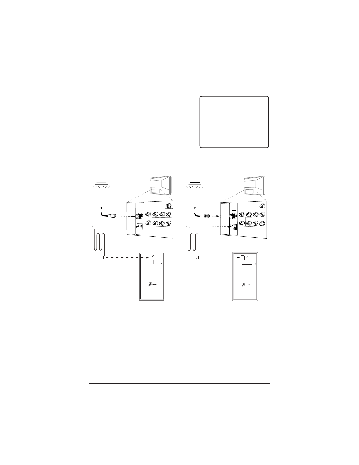
Page 52
QuickSet II Programmer
LT200
0
®
ZENITH ELECTRONICS CORPORATION, GLENVIEW, ILLINOIS, USA
• heartbeat power on
communications ok
• slow power on
no communications
• green battery ok
• red batter y low
Blink pattern
Color
Reset
Status
Indicator
Connect cable to
TV MPI Jack and
follow on screen
instructions
MPI
Antenna
Cable
Typical
TV Back
M.P.I.
Component Video Input
R Audio In L
R Audio L
Video In
Y
Pr
Pb
Matrix Out
LT2002
Clone Programmer
TV Back Panel
(Expanded View)
RF Coxial Wire
(75 ohm)
Antenna
Learn Master TV Setup
Typical MPI Connections
QuickSet II Programmer
LT2000
®
ZENITH ELECTRONICS CORPORATION, GLENVIEW, ILLINOIS, USA
• heartbeat power on
communications ok
• slow power on
no communications
• green battery ok
• red batter y low
Blink pattern
Color
Reset
Status
Indicator
Connect cable to
TV MPI Jack and
follow on screen
instructions
MPI
Antenna
Cable
Typical
TV Back
M.P.I.
Component Video Input
R Audio In L
R Audio L
Video In
Y
Pr
Pb
Matrix Out
LT2002
Clone Programmer
TV Back Panel
(Expanded View)
RF Coxial Wire
(75 ohm)
Antenna
Teach Other TV the Setup
Typical MPI Connections
THE CLONE HAS CONTROL OF THE TV
THE CLONE IS VERSION XX
THE TV IS VERSION XX
THE SW IS REVISION XX
CLONE CLOCK = XX:XX
TV CLOCK = XX:XX
-PRESS ANY KEY TO CONTINUE.
-DISCONNECT CLONE WHEN DONE.
LT2002 QuickSet Clone Programmer
Use the LT2002 QuickSet II “Clone”
Programmer to copy the setup from a
“master” TV then quickly transfer the
setup to duplicate TVs; must be the
same model number as the master TV.
LT2002
LT2002
The optional QuickSet II Clone Programmer (LT2002) allows custom setup and pro-
gramming information to be quickly copied from a master TV into multiple identi-
cal television sets. Once learned from the master, setup data is retained in the
LT2002 for future use.
When using the LT2002, cloning operations will go easier if the TV set is connect-
ed to a good quality signal and operating with a stable picture displayed. To oper-
ate the LT2002, use the indicated keys on the HP602, LP702 or MBR3447 LG
remotes, or the front panel keys on the TV receiver.
Notes: Use MPI port for cloning. Do not run Auto Program while cloning.

Page 53
Cloning Preparations
Before You Begin Cloning...
• Only use the MPI port for connecting
to MPI equipment.
• Do not run Auto Program while TV is
connected to clone programmer.
• The “master TV” should be connected
to a good, stable signal from an over-
the-air antenna or cable service and
turned on.
• Teaching and Learning is only possi-
ble between identical model LG TVs.
(However, the Clone programmer can
store 3 different master TV setups.)
WARNING: Copying a blank or incorrect
memory into a TV will cause
the TV to operate erratically or
become inoperable.
• Use an LG MBR Remote like the
MBR3447LG or the TV front panel con-
trols to operate Learning and Teaching
menus.
• Make sure that the batteries in the
Clone programmer are fresh.
• If the batteries are removed, the
Clone Clock time will be lost.
• Decide if you want to set the time
from the Clone programmer or copy the
time to the Clone programmer; from a
TV which has the clock set to the cur-
rent time.
• Follow the connection diagrams on
the previous page to connect the Clone
to a master TV and, after learning is
complete, to another TV to “teach” it
the setup.
• Setting the time and transferring it
to the Clone or another TV is a separate
procedure.
• Once a TV’s setup is copied to anoth-
er TV, that TV needs to be disconnected
from power for about 5 seconds to acti-
vate the newly copied setup.
• See Troubleshooting to solve prob-
lems.
A. Set Up a Master TV
Using an LG Multi-Brand remote like
the MBR3447LG, set up a “Master” TV
with custom settings and features as
described in the TV’s operating guide.
The master TV’s Setup is what you will
copy to the Clone Programmer and
transfer to TVs with the same model
number so they will operate identically.
B. Connect Clone to Master TV
If there is a good connection, the
“Clone has Control of TV” message will
appear. (See menu on the previous
page.)
A slow flashing green light indicates there is a problem with the communica-
tions between the TV and the programmer. In this case, check for a damaged
cable, poor contacts or other connection troubles.
If the status indicator is red, the programmer batteries are low and should
be replaced. Use 4 good-quality alkaline AA batteries.
LT2002 QuickSet Programmer

Page 54
Cloning
THE CLONE HAS CONTROL OF THE TV
THE CLONE IS VERSION XX
THE TV IS VERSION XX
THE SW IS REVISION XX
CLONE CLOCK = XX:XX
TV CLOCK = XX:XX
-PRESS ANY KEY TO CONTINUE.
-DISCONNECT CLONE WHEN DONE.
CLONE SELECTION MENU
(1) LEARN FROM TV
(2) TEACH TO TV
(3) SET CLONE CLOCK FROM TV
(4) SET TV CLOCK FROM CLONE
(5) DISPLAY TV SETUP
(6) DISPLAY CLONE SETUP
-TO CHANGE MENU ITEMS, PRESS
CHANNEL KEYS OR DIGITS.
-TO EXECUTE ITEM, PRESS ON/OFF,
POWER, OR ENTER
LT2002 QuickSet Programmer
C. Learn Setup from Master TV
Press 1 to select the “Learn From TV”
option, then press ON/OFF, POWER, or
ENTER to go to the Memory Bank
Selection Menu. Pick the Memory
”Bank” you want to store this Master
TV’s Setup in by pressing either Channel
key repeatedly to pick Memory 1, 2 or
3. (If you choose a Memory “Bank” that
already has a master TV’s setup in it, it
will be overwritten by this Master TV’s
setup).
Once the Clone memory bank is select-
ed, press ON/OFF, POWER or ENTER. The
Clone memory bank you have selected
will be shown. Press ON/OFF or POWER
to begin copying the master TV’s setup.
Ca. Set the Clock (Optional)
Set the time on the Master TV’s Clock.
(If the time has already been copied
from another TV into the Clone pro-
grammer, you can set the Master TV’s
clock by copying the time from the
Clone programmer.) The LT2002 Clone
Programmer can copy the current time
to both a master TV and to the Clone’s
internal clock; accurate to within one
minute. (Another reason that the Clone
programmer should be equipped with
fresh, high-quality alkaline batteries is
for it to keep the time as accurately as
possible).
Since the Clone Programmer’s time can-
not be set directly, the time needs to
be copied from an LG TV equipped with
M.P.I. Input capability.
Once the time is copied to the Clone
programmer, the current time can then
be transferred to another TV. (This can
be a Master TV, or another TV which
has had the features already set up).
D. Teach Master TV’s Setup to Another
Identical TV
Once Learning is complete, remove the
M.P.I. cable from the master TV and
connect it to the TV that you want to
copy the master TV’s setup to. With the
“TV is Controlled by Clone” message
displayed, press 2 or use either Channel
key to go to the “Teach to TV” option,
press ON/OFF, POWER or ENTER.
Follow on-screen instructions to trans-
fer the Setup and other information to
the “Learning” TV. After the “Teach to
TV is Complete” message is displayed,
press any key to return to the Clone
menus option, then press ON/OFF,
POWER or ENTER. If finished, remove
the M.P.I. Cable from the TV.
E. Disconnect TV Power for 5 Seconds
Unplug the TV power cord of the newly
“Cloned TV” from the power outlet for
about 5 seconds to activate the newly
copied Setup.

Page 55
Operation Notes
Clone Programmer/Cloning Procedure Troubleshooting
Problem Possible Cause(s) Possible Solution(s)
Clone Programmer
LED does not blink. • M.P.I. cord not connected. -Connect M.P.I. cord.
• TV not turned on. -TV must be on for clone to work.
• Weak batteries. -Install 4 fresh AA high-quality alkaline
batteries.
Clone menu hard • Weak signal. -Connect TV to a reliable signal Source.
to read.
No time set. • No time on Master TV. -Set time on master TV, copy time to
Clone Programmer.
Menu items 7-8 not • Not necessary. -Channel Labels already cloned; if they
on clone selection menu. were on Master TV.
Master and Other TVs
Cloning did not work. • Procedure interrupted. -Wait until procedure complete message
is displayed.
• Different TV models. -Cloning is only possible with identical
model TVs.
Clone time disappeared. • Batteries were removed. -Batteries must remain installed to retain
time settings.
Channel Labels not • Saved to other memory. -Must save channel labels to same
present on cloned TV. memory bank as master TV setup.
New Setup not present. • TV not reset. -Disconnect newly cloned TV from power
for 5 seconds.
LT2002 Clone Programmer
Disconnect the Clone from the TV when you are
finished; automatically switching it off. The real-
time clock continues to run after the main circuits
have been switched off.
Reset Clone After Static Shock
After replacing exhausted batteries, or if the pro-
grammer behaves strangely after a static shock,
use a paper clip or similar instrument inserted
through the small hole marked ”RESET” to activate
the internal reset switch and restore normal opera-
tion.
After a reset, check the real-time clock setting. It
may be necessary to reset the Clone Programmer
clock from a TV containing the correct time.
The LT2002 programmer is designed to be used
with TVs containing the 221-01006 and later
processors. Use with earlier TV sets may give
unpredictable results. The specific microprocessor
used in any TV set may be determined by activat-
ing the Installer Menu. The microprocessor part
number appears on the screen when the Installer
Menu is activated. Processors before the 221-01006-04
have a limited screen display capability. They can not
display entire screens as shown in the quick setup
instructions accompanying the LT2002 clone
programmer. Use the printed menu illustrations on
the quick setup sheet supplied with the Clone as an
aid to making your programming choices. (Although
the menus are not all displayed, the clone functions
all operate normally).
When cloning operations are complete, just unplug the LT2002 from the TV.
If the TV does not display a picture (blank screen) after a few seconds, just change channels.

Page 56
Troubleshooting
Some Quick and Easy Tips for Resolving Problems
Symptom(s) Possible Cause(s) Possible Solution(s) Page(s)
Power
No Power. • AC Power Cord not connected Connect power cord. 11
or power outlet doesn’t work. Try a different power outlet.
Local power failure?
No Source image. • Source turned off. Turn source equipment on.
• Source not selected. Select source. 22
Remote Control Problems
Remote doesn’t work. • Remote not in TV mode. Put remote into TV mode. 9
• TV software functioning. Wait until software function is complete.
• Not aimed at remote sensor. Point remote at TV Front Control Panel. 20
• Remote too far from TV or Move remote closer to TV or darken room.
IR path to TV obstructed. Remove obstructions.
• Weak batteries. Replace batteries. 11
• Wrong battery polarity. Check that “+” and “-” match in battery compartment. 11
• Too much light in room. Dim room light.
Caption/Text Problems
Picture has a big black • Caption/Text mode turned on. The CC (closed captions) option may be in 30
box on it, but the sound Text 1, 2, 3, or 4 mode. Select Caption 1, or OFF
is okay. in the Caption/Text menu.
No Closed Captions • Not available on program. Check local TV listings to see if available on broadcast. 30
or Text. • Not provided by broadcaster. Relocate over-the-air antenna.
(Even though CC indicated on OSD) Try a different channel with Closed Captions or Text.
• Not turned on. Pick a Closed Caption or Text option and turn Captions on.
Captions appear when • CC on Mute selected. Set Captions option to Off. 30
sound is muted.
Installer Menu Settings and TV Problems
Installer menu item settings dictate how the TV functions. If a feature is not
available or a problem can not be solved, check the installer menu settings to
assure feature and functional items are set to appropriate levels, etc.

Page 57
Troubleshooting
Some Quick and Easy Tips for Resolving Problems
Symptoms Possible Cause(s) Possible Solution(s) Page(s)
Picture Reception
Poor or no picture. * TV station problems. Try a different channel. 8/9/20
* Video menu not adjusted properly. Check Video menu option settings. 36
Local interference. * Check for disturbing source. The following may cause image problems or distortion:
Electrical appliances, powerful lights, cars, trucks;
computers or portable phones; medical equipment.
* Appliance too close to TV. If possible increase the distance between the TV
and the offending appliance. Or shut one of them off.
Poor or no color. * Sub-standard broadcast. Try a different channel. 8/9/20
* Sub-standard cable signal. Notify cable company of reception problem.
If a VCR is connected, play a tape.
Picture wobbles * RF not connected, loose. Make or tighten connection. 12/15
or drifts. * Local interference. Try different channel. 8/9/20
Turn off interfering appliance.
* Scrambled CATV channel. Tune to unscrambled channel. 8/9/20
No CATV reception. * Cable not connected. Connect cable to Antenna/Cable (RF) jack. 13/15
* Cable service interrupted. Contact cable service.
* Antenna set, not CATV. Select 'Cable TV' in Setup menu, run Auto Program. 19
Normal picture, poor * Audio muted. Press MUTE or volume right key to increase 8/9
or no sound. sound level.
* Broadcast problem. Try a different channel. 8/9/20
* A/V cables incorrectly connected. Install A/V cables correctly. 14/15/17/18
* Audio Out cable wrong. Install Matrix Out external amplifier/speaker 16
cable correctly.
* Front Surround turned off. Turn Front Surround On in the Audio menu. 35
* No 2nd Audio/ SAP on program. Choose another audio mode option or a 35
different program.
Snowy or * Wrong Ant. connection/location. Move antenna, check connection/location. 12/15
Poor Picture. * TV/VCR button set wrong. Set TV/VCR button on VCR correctly.
* Wrong output channel selected. Set output channels on all A/V equipment to 14/15
same channel (3 or 4).
* Loose connection. Check that all connections are correct. 12-18
* Broadcast problem. Try another channel. 8/9/20
* Video menu options set wrong. Check Video menu brightness controls. 36
TV turns Off. * Sleep Timer turned TV Off. Turn TV back on. 8/9/20
* Off Timer turned TV Off. Turn TV back on. 8/9/20
* Power failure. Check other power outlets.
* Power outlet controlled by switch. Connect TV power cord to outlet that is
(Switch turned off.) not controlled by a switch.
TV turns On. * On Timer turned TV On. Disable On/Off Timer. 29
TV does not turn * On/Off Timer option disabled. Go to Timer option in Setup menu and 29
On/Off per On/Off Timer enable On/Off Timer.
settings.

Page 58
Troubleshooting
Some Quick and Easy Tips for Resolving Problems
Symptoms Possible Cause(s) Possible Solution(s) Page(s)
Source Selection / Source Image Problems
Camport (Front • Equipment not connected. Connect Audio/Video equipment to 20
Audio/Video) source front Audio/Video.
not selectable.
No Camport image. • Equipment not turned on. Turn on equipment connected to front Video input. 20
(Front Video) • Not enabled. Enable Camport in Installer menu. 46
S- Video Source not • Camport (Front Video) Disconnect equipment connected to 20
selectable. connected. front Video jack.
• Not connected. Connect S-Video equipment to S-Video In. 16/20
No S-Video image. • Equipment not turned on. Turn on equipment connected to S-Video In.
No S-Video audio. • S-Video audio not Connect audio for S-Video to Audio In R - L. 16/20
connected. (Use Audio In Left jack to connect only one audio wire.)
Antenna/Cable • Front Video connected. Disconnect equipment connected to front Video. 20
not selectable. • S-Video equipment Disconnect S-Video equipment from front or 16/20
connected. rear jack panel.
No Antenna • Not Connected. Connect over-the-air antenna or cable service 12/13
Cable image. wire to Antenna/Cable jack.
Rear Audio Video • Front Video connected. Disconnect equipment from front Video jack. 20
not selectable. • S-Video equipment Disconnect S-Video equipment from front or 16/20
connected. rear jack panel.
Go to Setup menu, select Add/Del/Blank option. 25
Press MENU select “Added" in Add/Del/Blnk 25
option in Setup menu.
(See Installer menus.)
No rear Audio * Equipment not turned on. Turn on equipment connected to rear Audio/Video.
Video image.
* Equipment not connected. Connect equipment to rear Audio/Video. 14-18

Page 59
Maintenance
Routine TV Cabinet and Screen Cleaning
Careful and regular cleaning can extend the the useful service life of the TV. Be sure to turn the power off and pull out the
power cord before you begin any cleaning.
Screen Cleaning
1. Here’s a great way to keep the dust off the screen for a while. Wet a soft cloth in a mixture of lukewarm water and a
little fabric softener or dish washing detergent. Wring the cloth until it’s almost dry, and then use it to wipe the screen.
2. Make sure the excess water is off the screen, and then let it air-dry before turning it on.
Cabinet Cleaning
1. Use a soft cloth with a mild soap solution to wipe the cabinet. (Avoid using any harsh, industrial strength variety of
cleaner.)
2. Rinse the cloth and wipe the cabinet again.
3. Let the cabinet air-dry before turning the TV on.
Extended Absence
If the TV will be dormant for a long time, it’s a good idea to unplug the power to protect against possible damage from
lightning or power surges. If you use an off-air antenna, you may also want to disconnect it from the back of the TV.
If you unplug the TV, you may have to reset the clock using the Clock Set menu described earlier. See page 28.
Symptom(s) Possible Cause(s) Possible Solution(s) Page(s)
Parental Control Problems
User cannot access • Digital channel tuned in. Tune in an analog channel to access Parental Control 8/9
Parental Control menu. (Ch Preview not functional for menu with Ch Preview on remote.
digital channels on some models.)
User cannot operate • Digital channel tuned in. Tune in an analog channel to be able to navigate 8/9/20
Parental Control menu. (Ch Preview not functional for and set up Parental Control restrictions.
digital channels on some models.)
Guest has left Parental • Parental Control needs to Press and hold down MENU key until menu disappears. 37
Control active, password be reset. Key in 9-8-7-6 and press CC. (For this to work, Installer
is not known. menu item 0-1 Installer Seq needs to be set to 0.) 41
Protected/blocked • Program content is restricted. Key-in password and turn Lock On/Off (restrictions) Off.
message shows on-screen. Set to Off in Lock On/Off menu. 37-39
• Don’t know password. Tune to channel without Parental Control 37-39
“Content” restrictions.
Wait until restriction time expires.
TV-PG programs blocked. • TV- PG set to be blocked. Reset restrictions to PG- 13 so TV- PG 37-39
programs will appear.
Foul language is heard. • Foul language not blocked. Restrict Language in Content options on 37-39
Parental Control menu.
• Program is not rated. Restrict or block programs with no ratings.
Troubleshooting/Maintenance
Some Quick and Easy Tips for Resolving Problems

Page 60
Glossary
A list of definitions for some of the words found in this guide
75 OHM The wire that comes from an off-air antenna or cable service provider.
RF CABLE The end looks like a hex-shaped nut with a wire sticking through the middle.
It screws onto the threaded jack on the back of the TV.
300 TO 75 OHM A small device that connects a two-wire 300 ohm antenna to a 75 ohm RF jack.
ADAPTER They are usually about an inch long with two screws on one end and a round
opening with a wire sticking out on the other end.
A/V CABLES Audio/Video cables. Three cables bunched together—right audio (red),
left audio (white), and video (yellow). A/V cables are used for stereo playback
of videocassettes and for higher quality picture and sound from other A/V devices.
A/V DEVICE Any device that produces video or sound (VCR, DVD, cable box, or television).
ADDED Lets you add new channels to the list that the user can scroll through using
CH (Channel) Up/Down.
AMPLIFIER An electronic device that amplifies sound from a television, CD player, VCR, DVD,
or other Audio/Video device.
ANTENNA The physical receiver of television signals sent over the air. A large metal piece
of equipment does not always have to be visible to be using an antenna.
AUTO PROGRAM Auto Program has the TV automatically find all the channels available.
BLANK Channels that are Blanked will not have Video (shows a blank screen)
only audio, if present on channel. (Not available on digital channels.)
DELETED Lets you remove channels from the list that the user will scroll through
using CH (Channel) Up/Down.
DIGITAL TUNER Receives a digital signal and turns it into picture and sound.
INPUT Refers to an input jack that receives a signal from a TV, VCR,
or other Audio/Video device.
JACK A connection on the back of a TV, VCR, or other Audio/Video device.
MONO SOUND Mono (monaural) sound is one channel of sound. On more than one
speaker, all the speakers play the same audio.
M.P.I. Multiple Protocol Interface: LG protocol for external control of TV through RJ11
(M.P.I.) input jack on TV connections panel.
(M.P.I. jack is used for cloning TV’s features.)
OUTPUT Refers to the output jack that sends a signal out of a VCR, DVD,
or other A/V device.
2ND AUDIO Second Audio Programming (SAP) is another separate audio channel
PROGRAMMING available with some programming.
SAP Choosing SAP often refers to listening to audio in another language,
such as Spanish or French.
S-VIDEO Provides higher-quality picture and sound. (S-Video is also referred to as “Y-C”.)
SIGNAL Picture and sound traveling through a cable, or over the air, to the television.
STEREO SOUND Stereo (Stereophonic) sound refers to audio that’s divided into right and left sides.
TUNER Device that picks up the broadcast signal and turns it into picture and sound.
XDS Extended Data Service: Additional program information included on
the signal provided at the discretion of the broadcaster.

Page 61
Notes
This page is available to write any comments

Direct-View Welcome to the LG family! We believe that you will be pleased with your new TV.
Color TV Please read this warranty carefully, it is a “LIMITED WARRANTY” as defined under
Federal Law. This warranty gives you specific legal rights, and you may also have
other rights that vary from state-to-state within the U.S.A.
LG’s RESPONSIBILITY
Service Labor During a period of one year from effective warranty date, LG will provide service labor
by an LG authorized service center when needed, as determined by the LG service
center, as a result of manufacturing defects.
Parts New or remanufactured replacements for factory-defective parts will be supplied by an
LG authorized service center for one year from effective warranty date (color picture
tube — two years). Such replacement parts are warranted for the remaining portion of
the original warranty period.
Warranty Warranty service is provided in the institution in most cases. (Some repairs may require
Service the unit to be taken by the servicer to the repair facility and returned, at no additional
charge.) Call 1-888-865-3026 for further information.
This warranty covers manufacturing defects and does not cover installation, adjustment
of customer controls, installation or repair of antenna systems, cable converters or
cable company-supplied equipment; it also does not cover damage due to misuse,
abuse, negligence, acts of God or other causes beyond the control of LG. Any alteration
of the product after manufacture voids this warranty in its entirety.
THIS WARRANTY IS IN LIEU OF ANY OTHER WARRANTY, EXPRESS OR IMPLIED, INCLUDING WITHOUT LIMITA-
TION, ANY WARRANTY OF MERCHANTABILITY OR FITNESS FOR A PARTICULAR PURPOSE, AND LG SHALL NOT
BE LIABLE FOR ANY CONSEQUENTIAL, INDIRECT, OR INCIDENTAL DAMAGES OF ANY KIND, INCLUDING LOST
REVENUES OR PROFITS IN CONNECTION WITH THIS PRODUCT. SOME STATES DO NOT ALLOW LIMITATIONS ON
HOW LONG AN IMPLIED WARRANTY LASTS OR THE EXCLUSION OR LIMITATION OF INCIDENTAL OR CONSE-
QUENTIAL DAMAGES, SO THE ABOVE LIMITATIONS OR EXCLUSIONS MAY NOT APPLY TO YOU.
OWNER’S RESPONSIBILITY
Effective Warranty begins on the date of installation of the Commercial Products Direct View
Warranty Date Television Receiver. For your convenience, keep the dealer’s dated bill of sale or delivery
ticket as evidence of the purchase date.
Operating Guide Read the Installation Guide carefully so that you will understand the operation of the
TV and how to adjust the controls.
Antenna Reception problems caused by inadequate antenna or faulty antenna connections are
the owner’s responsibility.
Warranty For warranty service information, call 1-888-865-3026. Parts and service labor that are
Service LG’s responsibility (see above) will be provided without charge. Other service is at the
owner’s expense. If you have any problem in obtaining satisfactory warranty service,
call 1-888-865-3026. You must provide the model number, serial number and date of
purchase or date of original installation.
Warranty Before you ask for warranty service, read “Maintenance and Troubleshooting” in this
Service installation guide. You might avoid a service call.
For Customer Support/Service Please call:
1-888-865-3026
www.lgcommercial.com © Copyright 2007, LG Electronics U.S.A., Inc. 3828VA0524D
206-4043
Warranty


