Loading ...
Loading ...
Loading ...
25
ENGLISH
Main power
terminal block
Insulation sleeves
attachments
Fix firmly not
to be displaced
ODU-IDU
Communication cable
ODU-ODU
Communication cable
Main Power Connection Communication Connection
CAUTION
It should be wiring power cables or communication cables to avoid
interference with the oil level sensor. Otherwise, That oil level sensor
would be operated abnormally.
!
Checking the setting of outside units
Checking according to dip switch setting
- You can check the setting values of the Master outside unit from the
7 segment LED.
The dip switch setting should be changed when the power is OFF.
Checking the initial display
The number is sequentially appeared at the 7 segment in 5 seconds
after applying the power. This number represents the setting condition.
• Initial display order
• Master Unit • Slave Unit
Dip switch setting Dip switch setting ODU Setting
Slave 1
Slave 2
Order No Mean
①
8~20
Master model capacity(HP)
②
10~20
Slave 1 model capacity(HP)
③
10~20
Slave 2 model capacity(HP)
④
8~54
Total capacity(HP)
⑤
1 Cooling Only
2 Heat Pump
3 Heat Recovery
⑥
38 380V model
46 460V model
22 220V model
⑦
1 Full function
2 Core function
• Example) ARWN480DAS4
① ② ③ ④ ⑤ ⑥ ⑦
20 14 14 46 2 46 1
- After completing addressing, address of each indoor unit is indicated
on the wired remote control display window. (CH01, CH02,
CH03, ……, CH06 : Indicated as numbers of connected indoor units)
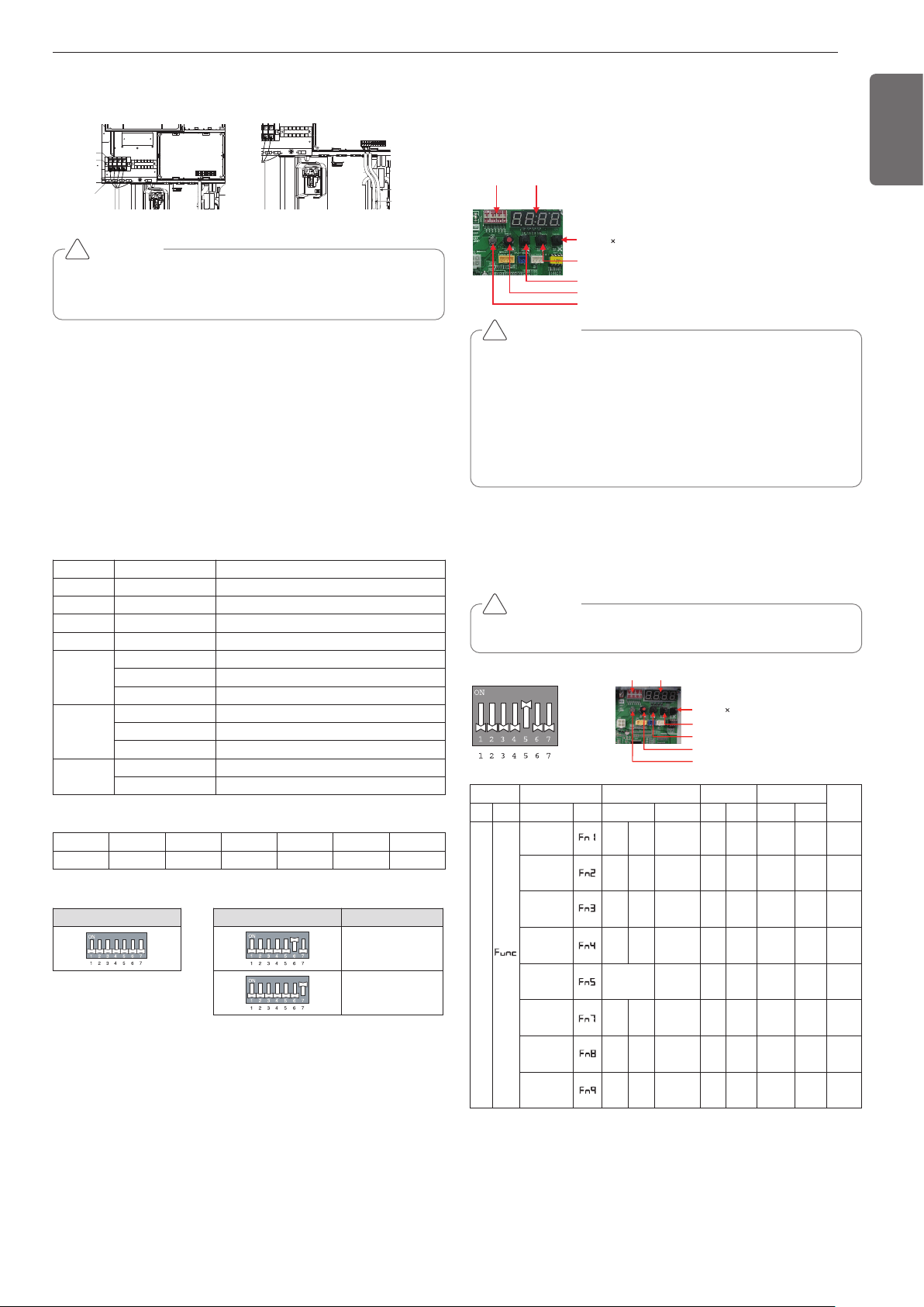
[MAIN PCB]
Automatic Addressing
The address of indoor units would be set by Automatic Addressing
- Wait for 3 minutes after supplying power.
(Master and Slave outside unit s, indoor units)
- Press RED button of the outside unit s for 5 seconds. (SW01C)
- A “88” is indicated on 7-segment LED of the outside unit PCB.
- For completing addressing, 2~7 minutes are required depending on
numbers of connected indoor units
-
Numbers of connected indoor units whose addressing is completed are
indicated for 30 seconds on 7-segment LED of the outside unit PCB.
DIP-SWITCH 7 - Segment
SW01C ( : confirm)
SW02C (ඔ : backward)
SW03C (ඖ : forward)
SW04C (
: cancel)
SW01D (reset)
CAUTION
• In replacement of the indoor unit PCB, always perform Automatic
addressing setting again (At that time, please check about using
Independent power module to any indoor unit.)
• If power supply is not applied to the indoor unit, operation error
occur.
• Automatic Addressing is only possible on the master Unit.
• Automatic Addressing has to be performed after 3 minutes to im-
prove communication.
!
Dip switch setting
Setting the function
Select the mode/function/option/value using ‘▶’, ‘◀’ Button and con-
firm that using the ‘●’ button after dip switch No.5 is turned on.
CAUTION
It is only executed when all indoor units are off.
!
DIP-SW01 7 - Segment
SW01C ( : confirm)
SW02C (ඔ : backward)
SW03C (ඖ : forward)
SW04C (
: cancel)
SW01D (reset)
* Functions save in EEPROM will be kept continuously, though the
system power was reset.
To cancel the function you need to set OFF.
Mode Function Option Value Action
Remarks
Content
Display1
Content
Display2
Content Display3
Content Display4
Implement Display5
In-
stal-
lation
Cool & Heat
Selector
oFF
op1~
op2
Selected
the option
- -
Change
the set
value
Blank
Save in
EEPROM
Geothermal
mode set-
ting
on
oFF
Selected
the option
- -
Change
the set
value
Blank
Save in
EEPROM
Sol. Valve
200 V out-
put
on
oFF
Selected
the option
- -
Change
the set
value
Blank
Save in
EEPROM
Variable
water flow
control
on
oFF
Selected
the option
- -
Change
the set
value
Blank
Save in
EEPROM
Outside unit
address
-
-
0~254
set
the
value
Change
the set
value
Blank
Save in
EEPROM
Target
pressure
adjusting
oFF
op1~
op4
Selected
the option
- -
Change
the set
value
Blank
Save in
EEPROM
Use Sump
Heater
on
oFF
Selected
the option
- -
Change
the set
value
Blank
Save in
EEPROM
IDU capacity
adjusting
on
oFF
Selected
the option
- -
Change
the set
value
Blank
Save in
EEPROM
Loading ...
Loading ...
Loading ...