OWNERS GUIDE
MARVEL PROFESSIONAL UNDERCOUNTER REFRIGERATION
THE ORIGINAL REFRIGERATION EXPERTS SINCE 1892
FOR MODEL # MPWC424
Welcome to the Marvel Experience
Thank you for choosing our quality American-built product
to add to your home. We are thrilled to welcome you to
our growing community of Marvel owners, who trust in our
products and our support.
The information in this guide is intended to help you install
and maintain your new Marvel undercounter model to pro-
tect and prolong its lifetime. We encourage you to contact
our Technical Support team at (616) 754-5601 with any
questions.
Got a Marvelous Design?
We would love to see how your Marvel product looks in its
new home. Send us photos at marketing@marvelrefrigera-
tion.com, and we might feature your Marvel home design
on our website and social media!
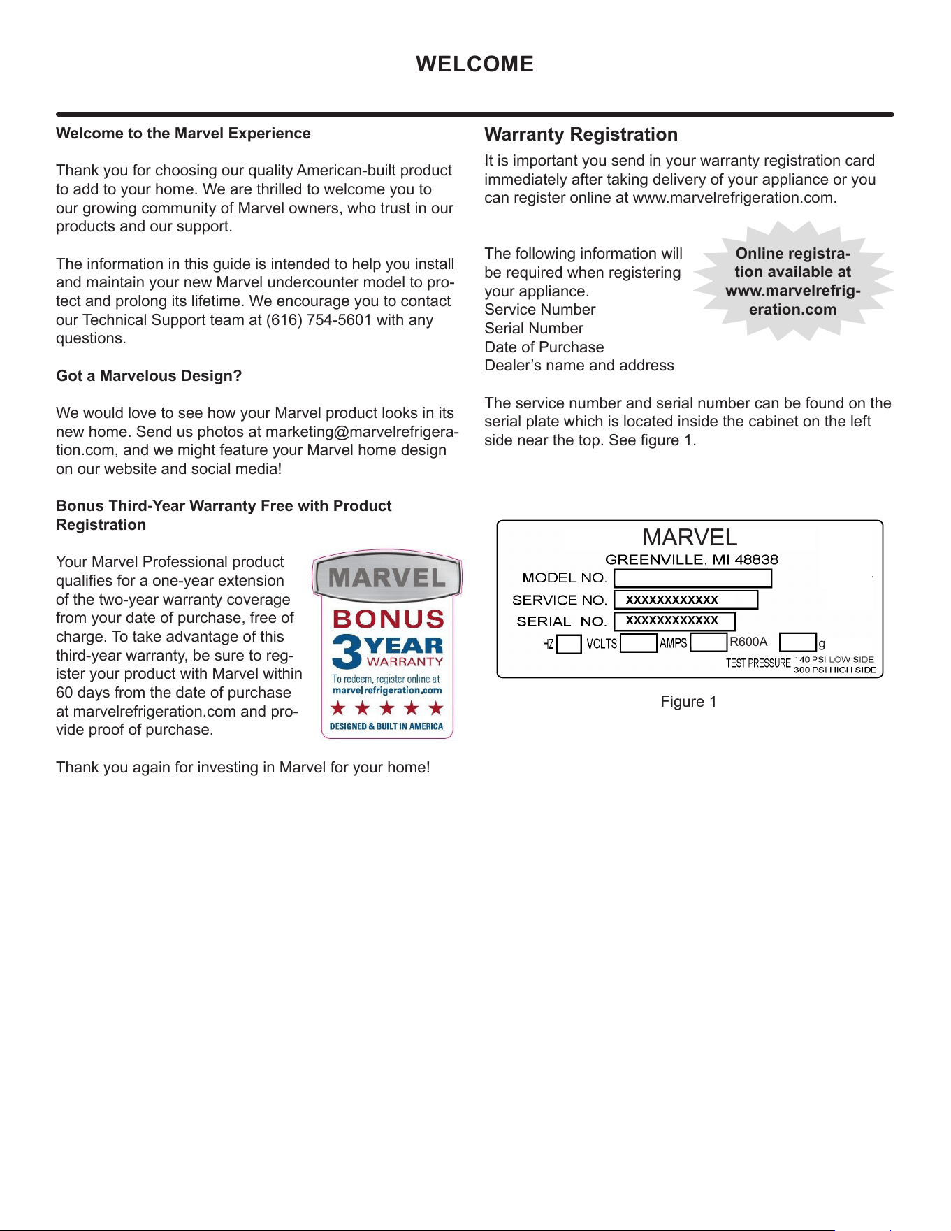
Bonus Third-Year Warranty Free with Product
Registration
Your Marvel Professional product
qualies for a one-year extension
of the two-year warranty coverage
from your date of purchase, free of
charge. To take advantage of this
third-year warranty, be sure to reg-
ister your product with Marvel within
60 days from the date of purchase
at marvelrefrigeration.com and pro-
vide proof of purchase.
Thank you again for investing in Marvel for your home!
XXXXXXXXXXXX
XXXXXXXXXXXX
MARVEL
g
Figure 1
R600A
WELCOME
It is important you send in your warranty registration card
immediately after taking delivery of your appliance or you
can register online at www.marvelrefrigeration.com.
The following information will
be required when registering
your appliance.
Service Number
Serial Number
Date of Purchase
Dealer’s name and address
The service number and serial number can be found on the
serial plate which is located inside the cabinet on the left
side near the top. See gure 1.
Warranty Registration
Online registra-
tion available at
www.marvelrefrig-
eration.com
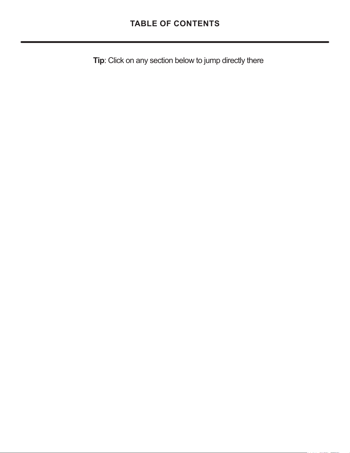
TABLE OF CONTENTS
Tip: Click on any section below to jum
p directly there
Safety
Important Safety Instructions
Installation
Unpacking Your Appliance
Electrical
Cutout & Product Dimensions
Installing Your Appliance
Side-by-Side & Stacking Installations
Installing the anti-tip device
Door Reversal
Maintenance
Care and Cleaning
Extended Non-Use
Operating Instructions
Using Your Electronic Control
Shelving and Contents
Interior Adjustments
Energy Savng Tips
Service
Obtaining Service
Wire Diagram
Product Liability
Ordering Replacement Parts
R600a Specifications
System Diagnosis Guide
Compressor Specifications
Troubleshooting Extended
Control Operation - Service
Thermistor
Warranty
3
NOTE
!
CAUTION
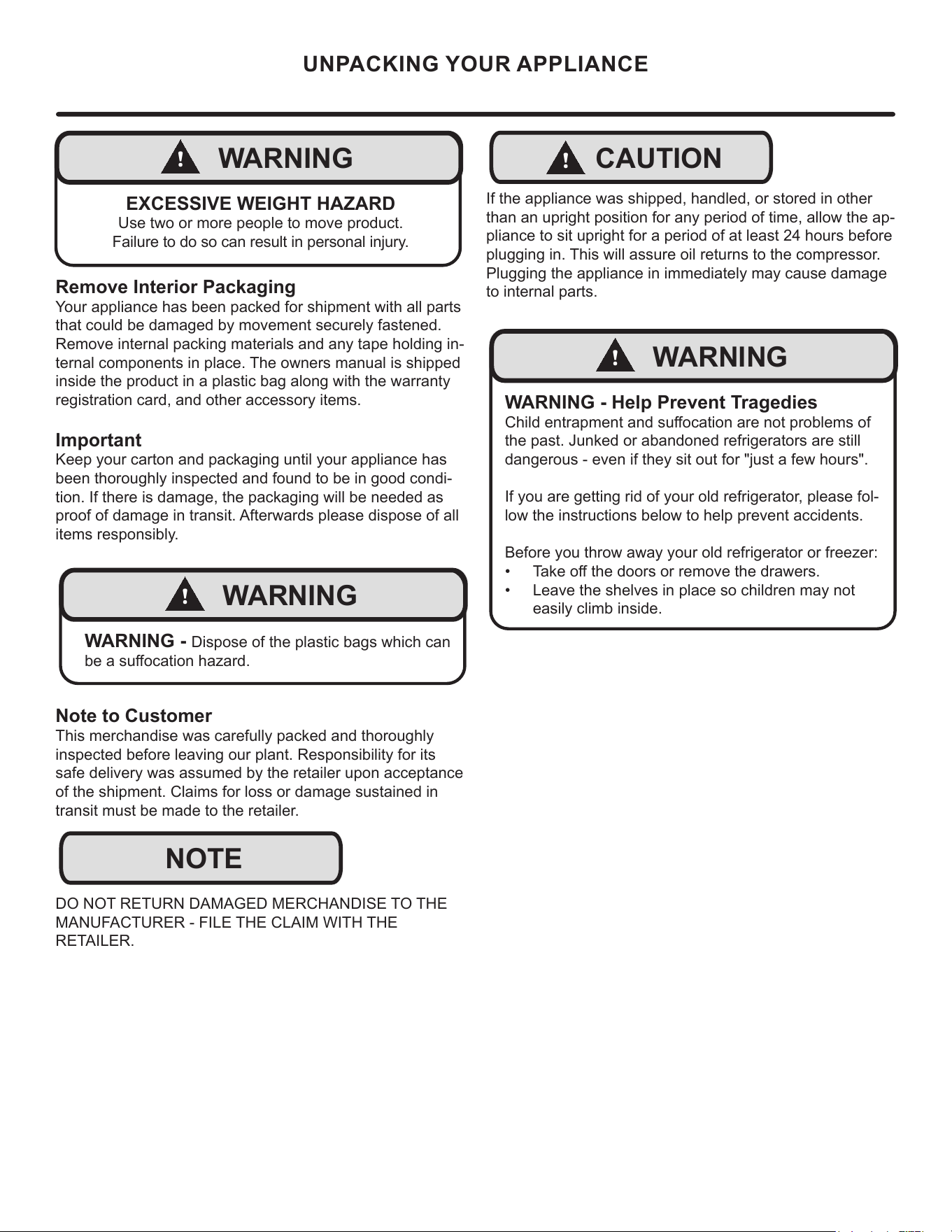
Important Safety Instructions
Warnings and safety instructions appearing in this guide
are not meant to cover all possible conditions and situa-
tions that may occur. Common sense, caution, and care
must be exercised when installing, maintaining, or operat-
ing this appliance.
Recognize Safety Symbols,
Words, and Labels.
CAUTION-Hazards or unsafe practices which could re-
sult in personal injury or property / product damage.
NOTE-Important information to help assure a problem
free installation and operation.
!
WARNING
WARNING - You can be killed or seriously injured
if you do not follow these instructions.
!
WARNING
State of California Proposition 65 Warning:
This product contains one or more chemicals known
to the State of California to cause cancer.
!
WARNING
State of California Proposition 65 Warning:
This product contains one or more chemicals known
to the State of California to cause birth defects or
other reproductive harm.
!
WARNING
WARNING - This unit contains R600a (Isobutane)
which is a ammable hydrocarbon. It is safe for regular
use. Do not use sharp objects to expedite defrosting.
Do not damage refrigerant circuit.
IMPORTANT SAFETY INSTRUCTIONS
4
NOTE
!
CAUTION
!
WARNING
WARNING - Dispose of the plastic bags which can
be a suocation hazard.
!
WARNING
WARNING - Help Prevent Tragedies
Child entrapment and suocation are not problems of
the past. Junked or abandoned refrigerators are still
dangerous - even if they sit out for "just a few hours".
If you are getting rid of your old refrigerator, please fol-
low the instructions below to help prevent accidents.
Before you throw away your old refrigerator or freezer:
• Take o the doors or remove the drawers.
• Leave the shelves in place so children may not
easily climb inside.
!
WARNING
EXCESSIVE WEIGHT HAZARD
Use two or more people to move product.
Failure to do so can result in personal injury.
Remove Interior Packaging
Your appliance has been packed for shipment with all parts
that could be damaged by movement securely fastened.
Remove internal packing materials and any tape holding in-
ternal components in place. The owners manual is shipped
inside the product in a plastic bag along with the warranty
registration card, and other accessory items.
Important
Keep your carton and packaging until your appliance has
been thoroughly inspected and found to be in good condi-
tion. If there is damage, the packaging will be needed as
proof of damage in transit. Afterwards please dispose of all
items responsibly.
Note to Customer
This merchandise was carefully packed and thoroughly
inspected before leaving our plant. Responsibility for its
safe delivery was assumed by the retailer upon acceptance
of the shipment. Claims for loss or damage sustained in
transit must be made to the retailer.
DO NOT RETURN DAMAGED MERCHANDISE TO THE
MANUFACTURER - FILE THE CLAIM WITH THE
RETAILER.
If the appliance was shipped, handled, or stored in other
than an upright position for any period of time, allow the ap-
pliance to sit upright for a period of at least 24 hours before
plugging in. This will assure oil returns to the compressor.
Plugging the appliance in immediately may cause damage
to internal parts.
UNPACKING YOUR APPLIANCE
5
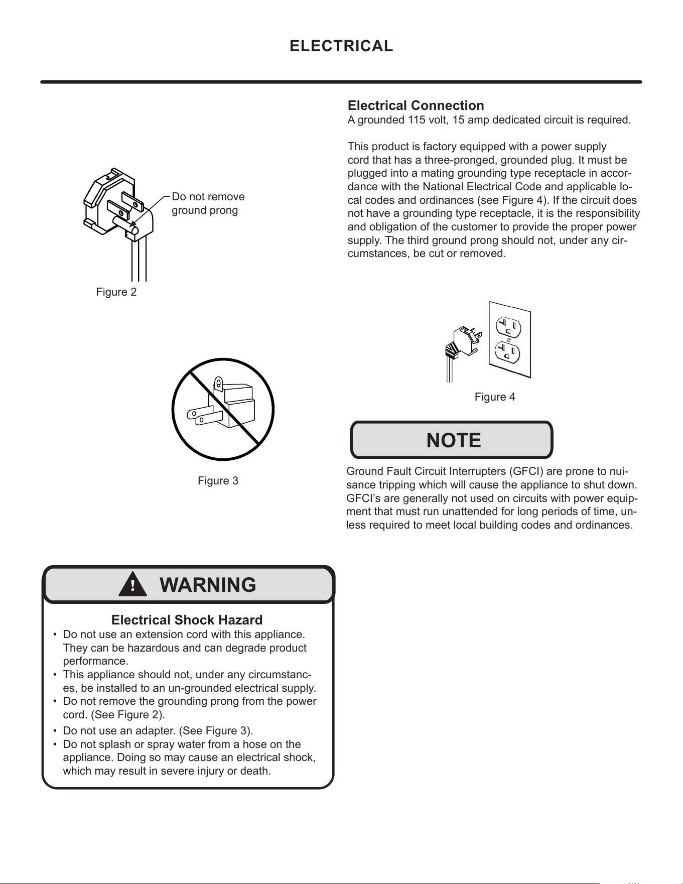
Electrical Connection
A grounded 115 volt, 15 amp dedicated circuit is required.
This product is factory equipped with a power supply
cord that has a three-pronged, grounded plug. It must be
plugged into a mating grounding type receptacle in accor-
dance with the National Electrical Code and applicable lo-
cal codes and ordinances (see Figure 4). If the circuit does
not have a grounding type receptacle, it is the responsibility
and obligation of the customer to provide the proper power
supply. The third ground prong should not, under any cir-
cumstances, be cut or removed.
Figure 4
NOTE
Ground Fault Circuit Interrupters (GFCI) are prone to nui-
sance tripping which will cause the appliance to shut down.
GFCI’s are generally not used on circuits with power equip-
ment that must run unattended for long periods of time, un-
less required to meet local building codes and ordinances.
ELECTRICAL
Figure 2
Do not remove
ground prong
Figure 3
Electrical Shock Hazard
• Do not use an extension cord with this appliance.
They can be hazardous and can degrade product
performance.
• This appliance should not, under any circumstanc-
es, be installed to an un-grounded electrical supply.
• Do not remove the grounding prong from the power
cord. (See Figure 2).
• Do not use an adapter. (See Figure 3).
• Do not splash or spray water from a hose on the
appliance. Doing so may cause an electrical shock,
which may result in severe injury or death.
!
WARNING
6
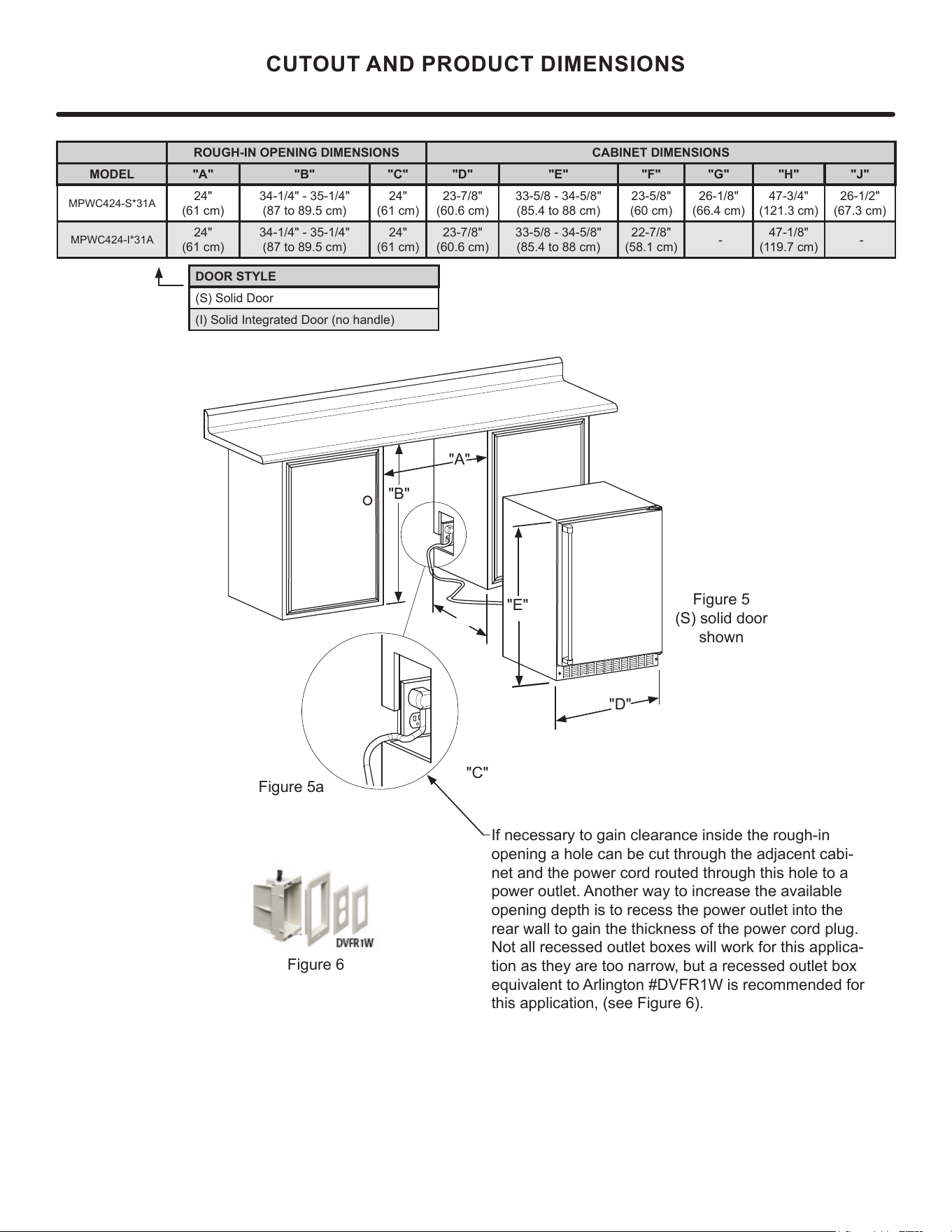
"C"
CUTOUT AND PRODUCT DIMENSIONS
"A"
"B"
"D"
"E"
Figure 5
(S) solid door
shown
Figure 5a
If necessary to gain clearance inside the rough-in
opening a hole can be cut through the adjacent cabi-
net and the power cord routed through this hole to a
power outlet. Another way to increase the available
opening depth is to recess the power outlet into the
rear wall to gain the thickness of the power cord plug.
Not all recessed outlet boxes will work for this applica-
tion as they are too narrow, but a recessed outlet box
equivalent to Arlington #DVFR1W is recommended for
this application, (see Figure 6).
Figure 6
ROUGH-IN OPENING DIMENSIONS CABINET DIMENSIONS
MODEL "A" "B" "C" "D" "E" "F" "G" "H" "J"
MPWC424-S*31A
24"
(61 cm)
34-1/4" - 35-1/4"
(87 to 89.5 cm)
24"
(61 cm)
23-7/8"
(60.6 cm)
33-5/8 - 34-5/8"
(85.4 to 88 cm)
23-5/8"
(60 cm)
26-1/8"
(66.4 cm)
47-3/4"
(121.3 cm)
26-1/2"
(67.3 cm)
MPWC424-I*31A
24"
(61 cm)
34-1/4" - 35-1/4"
(87 to 89.5 cm)
24"
(61 cm)
23-7/8"
(60.6 cm)
33-5/8 - 34-5/8"
(85.4 to 88 cm)
22-7/8"
(58.1 cm)
-
47-1/8"
(119.7 cm)
-
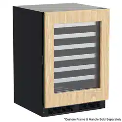
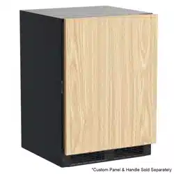
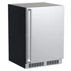
DOOR STYLE
(S) Solid Door
(I) Solid Integrated Door (no handle)
7
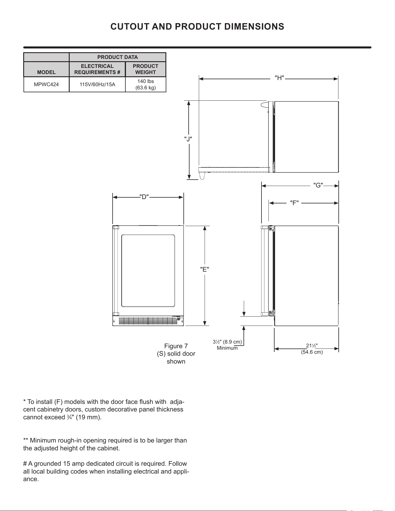
"D"
"E"
"F"
"G"
"H"
"J"
CUTOUT AND PRODUCT DIMENSIONS
PRODUCT DATA
MODEL
ELECTRICAL
REQUIREMENTS #
PRODUCT
WEIGHT
MPWC424 115V/60Hz/15A
140 lbs
(63.6 kg)
* To install (F) models with the door face ush with adja-
cent cabinetry doors, custom decorative panel thickness
cannot exceed
3
⁄4" (19 mm).
** Minimum rough-in opening required is to be larger than
the adjusted height of the cabinet.
# A grounded 15 amp dedicated circuit is required. Follow
all local building codes when installing electrical and appli-
ance.
3
1
⁄2" (8.9 cm)
Minimum
Figure 7
(S) solid door
shown
21
1
⁄2"
(54.6 cm)
8
!
CAUTION
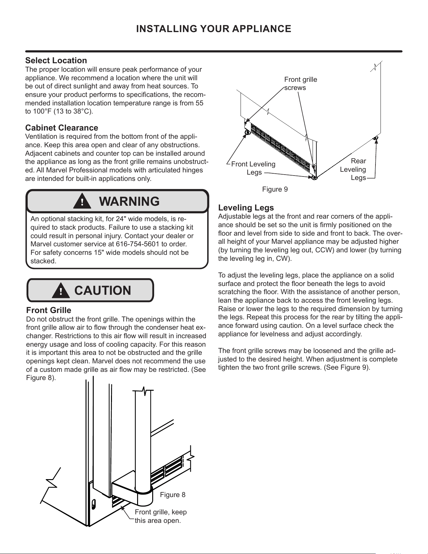
Front grille
screws
Select Location
The proper location will ensure peak performance of your
appliance. We recommend a location where the unit will
be out of direct sunlight and away from heat sources. To
ensure your product performs to specications, the recom-
mended installation location temperature range is from 55
to 100°F (13 to 38°C).
Cabinet Clearance
Ventilation is required from the bottom front of the appli-
ance. Keep this area open and clear of any obstructions.
Adjacent cabinets and counter top can be installed around
the appliance as long as the front grille remains unobstruct-
ed. All Marvel Professional models with articulated hinges
are intended for built-in applications only.
Front Grille
Do not obstruct the front grille. The openings within the
front grille allow air to ow through the condenser heat ex-
changer. Restrictions to this air ow will result in increased
energy usage and loss of cooling capacity. For this reason
it is important this area to not be obstructed and the grille
openings kept clean. Marvel does not recommend the use
of a custom made grille as air ow may be restricted. (See
Figure 8).
INSTALLING YOUR APPLIANCE
!
WARNING
An optional stacking kit, for 24" wide models, is re-
quired to stack products. Failure to use a stacking kit
could result in personal injury. Contact your dealer or
Marvel customer service at 616-754-5601 to order.
For safety concerns 15" wide models should not be
stacked.
Figure 9
Front Leveling
Legs
Leveling Legs
Adjustable legs at the front and rear corners of the appli-
ance should be set so the unit is rmly positioned on the
oor and level from side to side and front to back. The over-
all height of your Marvel appliance may be adjusted higher
(by turning the leveling leg out, CCW) and lower (by turning
the leveling leg in, CW).
To adjust the leveling legs, place the appliance on a solid
surface and protect the oor beneath the legs to avoid
scratching the oor. With the assistance of another person,
lean the appliance back to access the front leveling legs.
Raise or lower the legs to the required dimension by turning
the legs. Repeat this process for the rear by tilting the appli-
ance forward using caution. On a level surface check the
appliance for levelness and adjust accordingly.
The front grille screws may be loosened and the grille ad-
justed to the desired height. When adjustment is complete
tighten the two front grille screws. (See Figure 9).
Rear
Leveling
Legs
Figure 8
Front grille, keep
this area open.
9
SIDE-BY-SIDE AND STACKING INSTALLATIONS
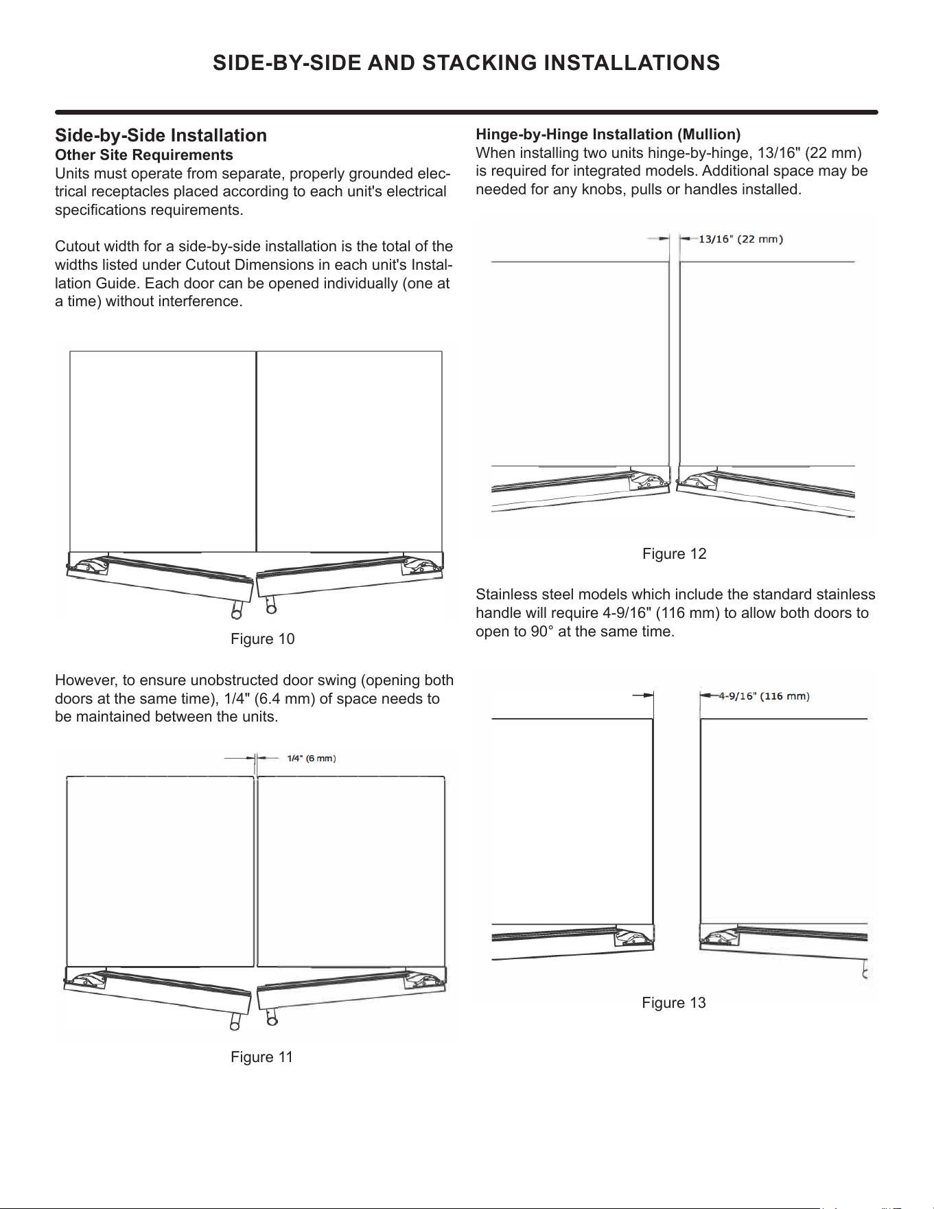
Side-by-Side Installation
Other Site Requirements
Units must operate from separate, properly grounded elec-
trical receptacles placed according to each unit's electrical
specications requirements.
Cutout width for a side-by-side installation is the total of the
widths listed under Cutout Dimensions in each unit's Instal-
lation Guide. Each door can be opened individually (one at
a time) without interference.
Figure 10
However, to ensure unobstructed door swing (opening both
doors at the same time), 1/4" (6.4 mm) of space needs to
be maintained between the units.
Hinge-by-Hinge Installation (Mullion)
When installing two units hinge-by-hinge, 13/16" (22 mm)
is required for integrated models. Additional space may be
needed for any knobs, pulls or handles installed.
Stainless steel models which include the standard stainless
handle will require 4-9/16" (116 mm) to allow both doors to
open to 90° at the same time.
Figure 11
Figure 12
Figure 13
10
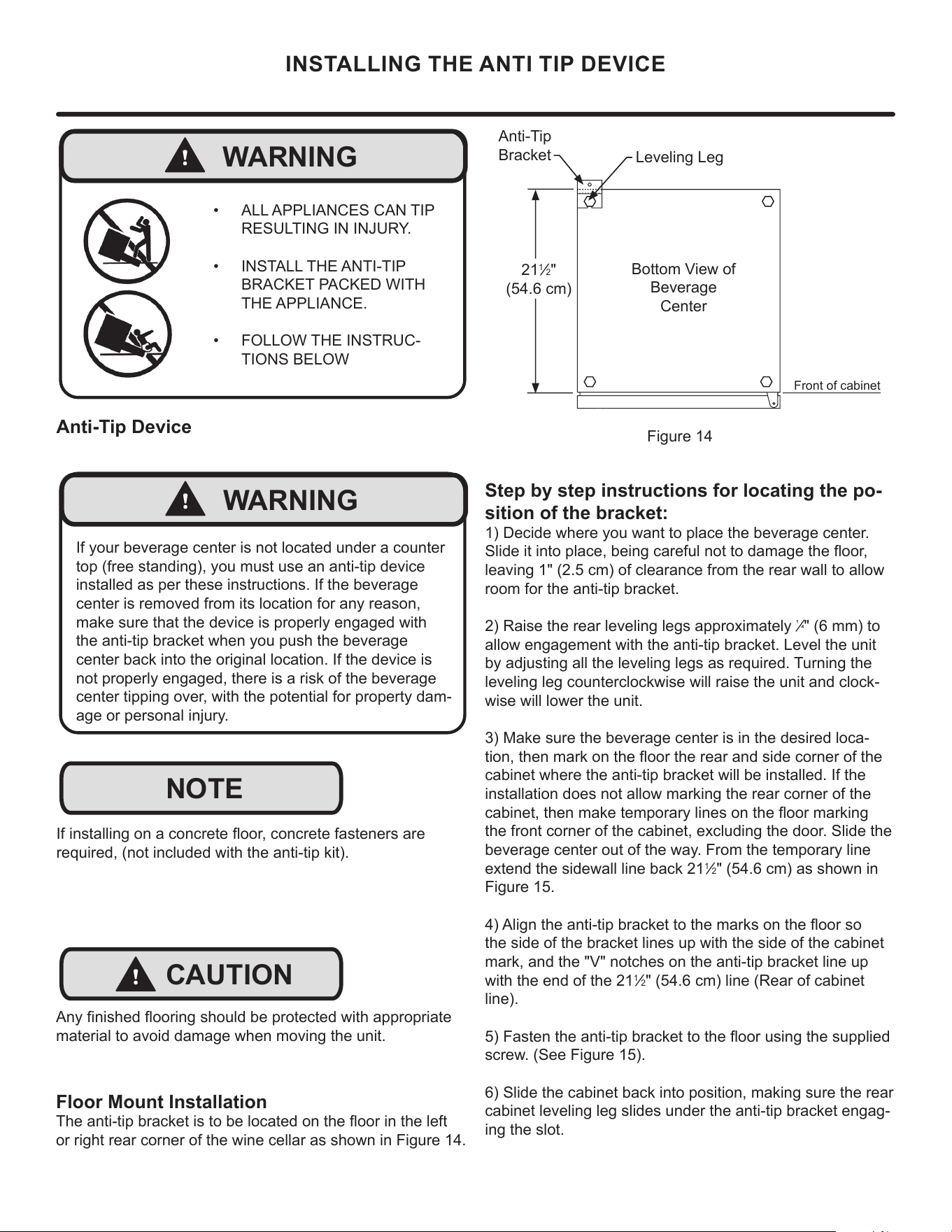
INSTALLING THE ANTI TIP DEVICE
Step by step instructions for locating the po-
sition of the bracket:
1) Decide where you want to place the beverage center.
Slide it into place, being careful not to damage the oor,
leaving 1" (2.5 cm) of clearance from the rear wall to allow
room for the anti-tip bracket.
2) Raise the rear leveling legs approximately
1
⁄4" (6 mm) to
allow engagement with the anti-tip bracket. Level the unit
by adjusting all the leveling legs as required. Turning the
leveling leg counterclockwise will raise the unit and clock-
wise will lower the unit.
3) Make sure the beverage center is in the desired loca-
tion, then mark on the oor the rear and side corner of the
cabinet where the anti-tip bracket will be installed. If the
installation does not allow marking the rear corner of the
cabinet, then make temporary lines on the oor marking
the front corner of the cabinet, excluding the door. Slide the
beverage center out of the way. From the temporary line
extend the sidewall line back 21
1
⁄2" (54.6 cm) as shown in
Figure 15.
4) Align the anti-tip bracket to the marks on the oor so
the side of the bracket lines up with the side of the cabinet
mark, and the "V" notches on the anti-tip bracket line up
with the end of the 21
1
⁄2" (54.6 cm) line (Rear of cabinet
line).
5) Fasten the anti-tip bracket to the oor using the supplied
screw. (See Figure 15).
6) Slide the cabinet back into position, making sure the rear
cabinet leveling leg slides under the anti-tip bracket engag-
ing the slot.
Front of cabinet
Figure 14
21
1
⁄2"
(54.6 cm)
Anti-Tip
Bracket
Leveling Leg
Bottom View of
Beverage
Center
Floor Mount Installation
The anti-tip bracket is to be located on the oor in the left
or right rear corner of the wine cellar as shown in Figure 14.
!
WARNING
• ALL APPLIANCES CAN TIP
RESULTING IN INJURY.
• INSTALL THE ANTI-TIP
BRACKET PACKED WITH
THE APPLIANCE.
• FOLLOW THE INSTRUC-
TIONS BELOW
!
CAUTION
NOTE
Any nished ooring should be protected with appropriate
material to avoid damage when moving the unit.
If installing on a concrete oor, concrete fasteners are
required, (not included with the anti-tip kit).
Anti-Tip Device
!
WARNING
If your beverage center is not located under a counter
top (free standing), you must use an anti-tip device
installed as per these instructions. If the beverage
center is removed from its location for any reason,
make sure that the device is properly engaged with
the anti-tip bracket when you push the beverage
center back into the original location. If the device is
not properly engaged, there is a risk of the beverage
center tipping over, with the potential for property dam-
age or personal injury.
11
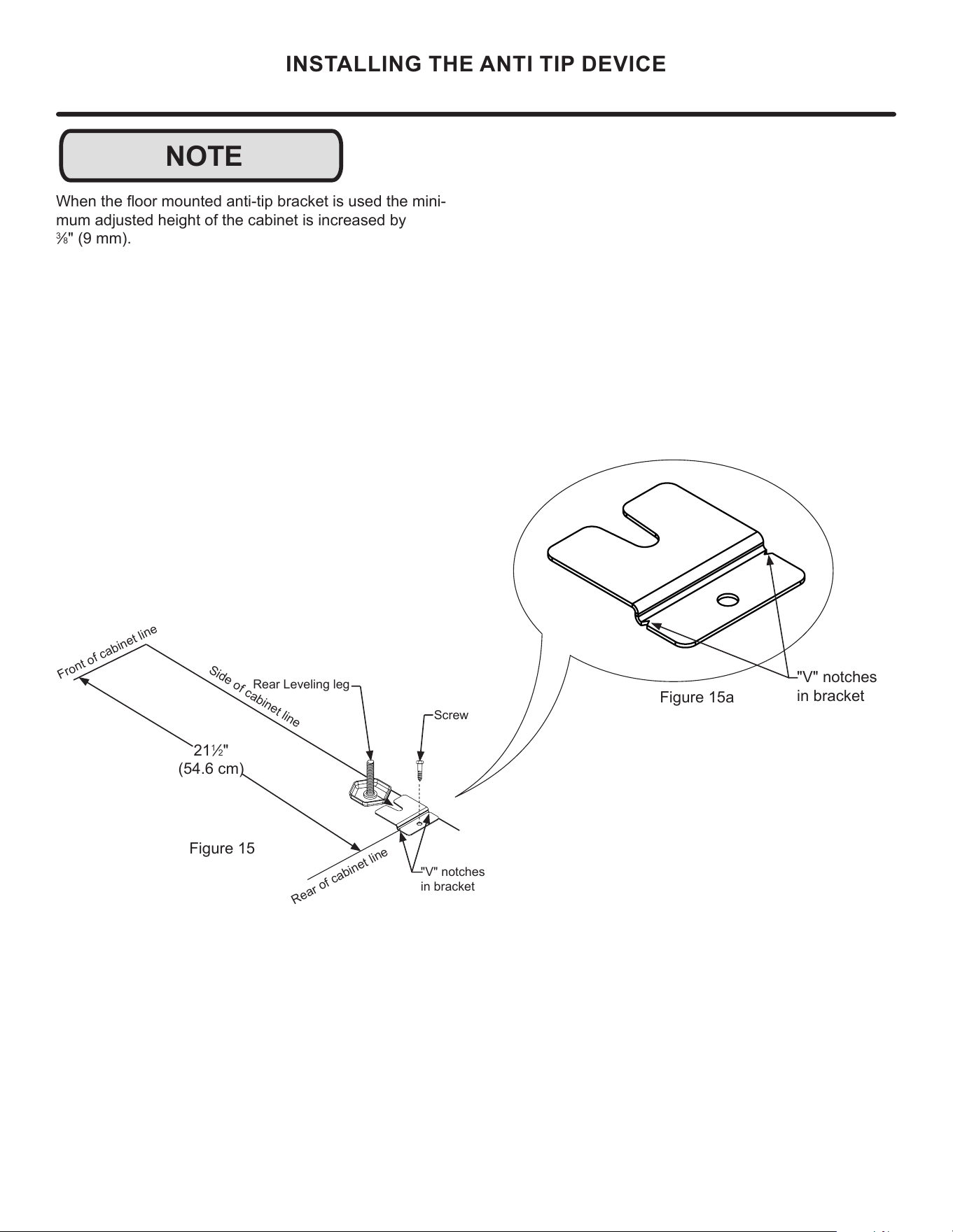
NOTE
INSTALLING THE ANTI TIP DEVICE
When the oor mounted anti-tip bracket is used the mini-
mum adjusted height of the cabinet is increased by
3
⁄8" (9 mm).
Figure 15a
"V" notches
in bracket
"V" notches
in bracket
Figure 15
21
1
⁄2"
(54.6 cm)
Front of cabinet line
Rear Leveling leg
Side of cabinet line
Rear of cabinet line
Screw
12
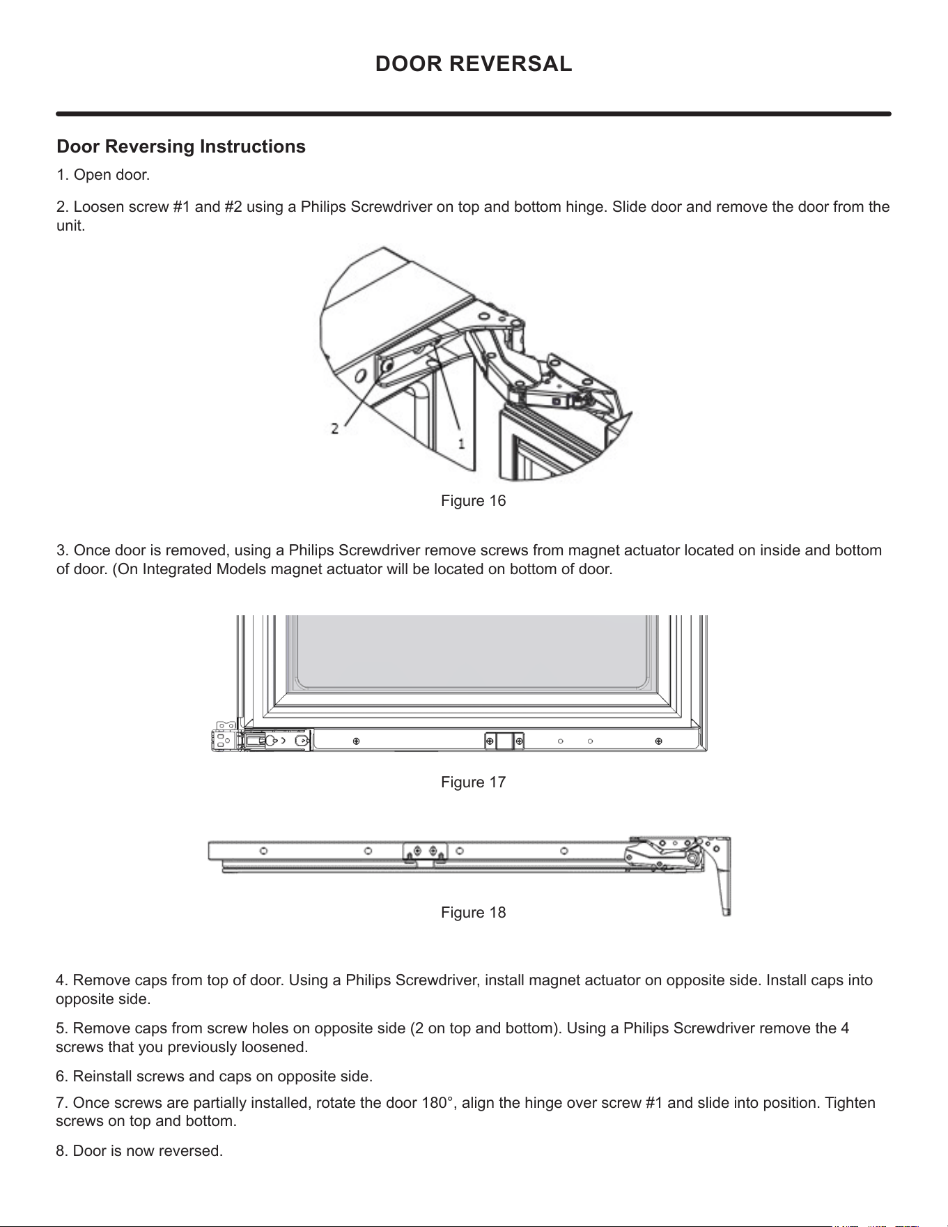
Door Reversing Instructions
1. Open door.
2. Loosen screw #1 and #2 using a Philips Screwdriver on top and bottom hinge. Slide door and remove the door from the
unit.
3. Once door is removed, using a Philips Screwdriver remove screws from magnet actuator located on inside and bottom
of door. (On Integrated Models magnet actuator will be located on bottom of door.
Figure 16
Figure 17
Figure 18
4. Remove caps from top of door. Using a Philips Screwdriver, install magnet actuator on opposite side. Install caps into
opposite side.
5. Remove caps from screw holes on opposite side (2 on top and bottom). Using a Philips Screwdriver remove the 4
screws that you previously loosened.
6. Reinstall screws and caps on opposite side.
7. Once screws are partially installed, rotate the door 180°, align the hinge over screw #1 and slide into position. Tighten
screws on top and bottom.
8. Door is now reversed.
DOOR REVERSAL
"V" notches
in bracket
13
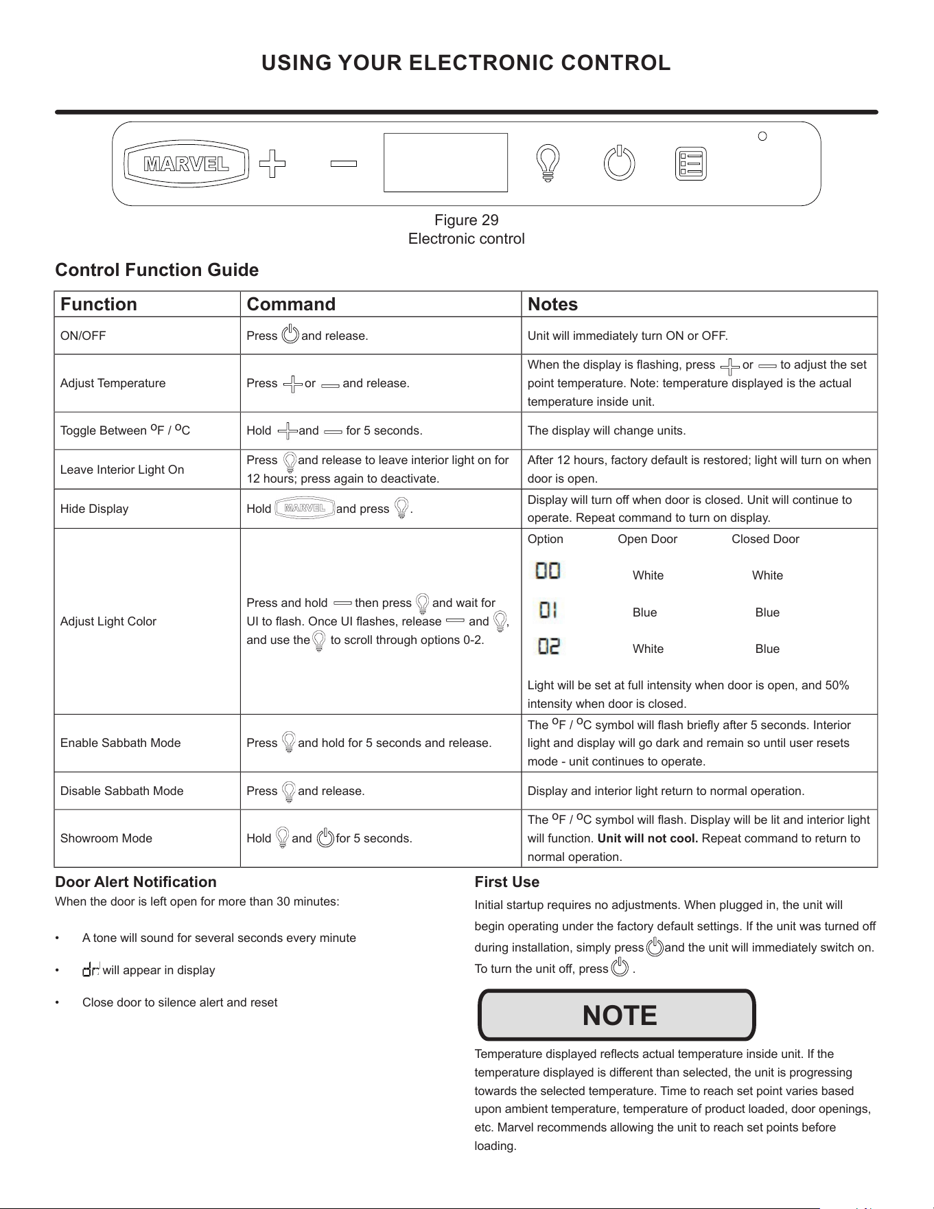
USING YOUR ELECTRONIC CONTROL
Control Function Guide
Function Command Notes
ON/OFF Press and release. Unit will immediately turn ON or OFF.
Adjust Temperature Press or and release.
When the display is ashing, press or to adjust the set
point temperature. Note: temperature displayed is the actual
temperature inside unit.
Toggle Between
o
F /
o
C Hold and for 5 seconds. The display will change units.
Leave Interior Light On
Press and release to leave interior light on for
12 hours; press again to deactivate.
After 12 hours, factory default is restored; light will turn on when
door is open.
Hide Display Hold and press .
Display will turn o when door is closed. Unit will continue to
operate. Repeat command to turn on display.
Adjust Light Color
Press and hold then press and wait for
UI to ash. Once UI ashes, release and ,
and use the to scroll through options 0-2.
Option Open Door Closed Door
White White
Blue Blue
White Blue
Light will be set at full intensity when door is open, and 50%
intensity when door is closed.
Enable Sabbath Mode Press and hold for 5 seconds and release.
The
o
F /
o
C symbol will ash briey after 5 seconds. Interior
light and display will go dark and remain so until user resets
mode - unit continues to operate.
Disable Sabbath Mode Press and release. Display and interior light return to normal operation.
Showroom Mode Hold and for 5 seconds.
The
o
F /
o
C symbol will ash. Display will be lit and interior light
will function. Unit will not cool. Repeat command to return to
normal operation.
Door Alert Notication
When the door is left open for more than 30 minutes:
• A tone will sound for several seconds every minute
• will appear in display
• Close door to silence alert and reset
First Use
Initial startup requires no adjustments. When plugged in, the unit will
begin operating under the factory default settings. If the unit was turned o
during installation, simply press and the unit will immediately switch on.
To turn the unit o, press .
Temperature displayed reects actual temperature inside unit. If the
temperature displayed is dierent than selected, the unit is progressing
towards the selected temperature. Time to reach set point varies based
upon ambient temperature, temperature of product loaded, door openings,
etc. Marvel recommends allowing the unit to reach set points before
loading.
NOTE
Figure 29
Electronic control
14
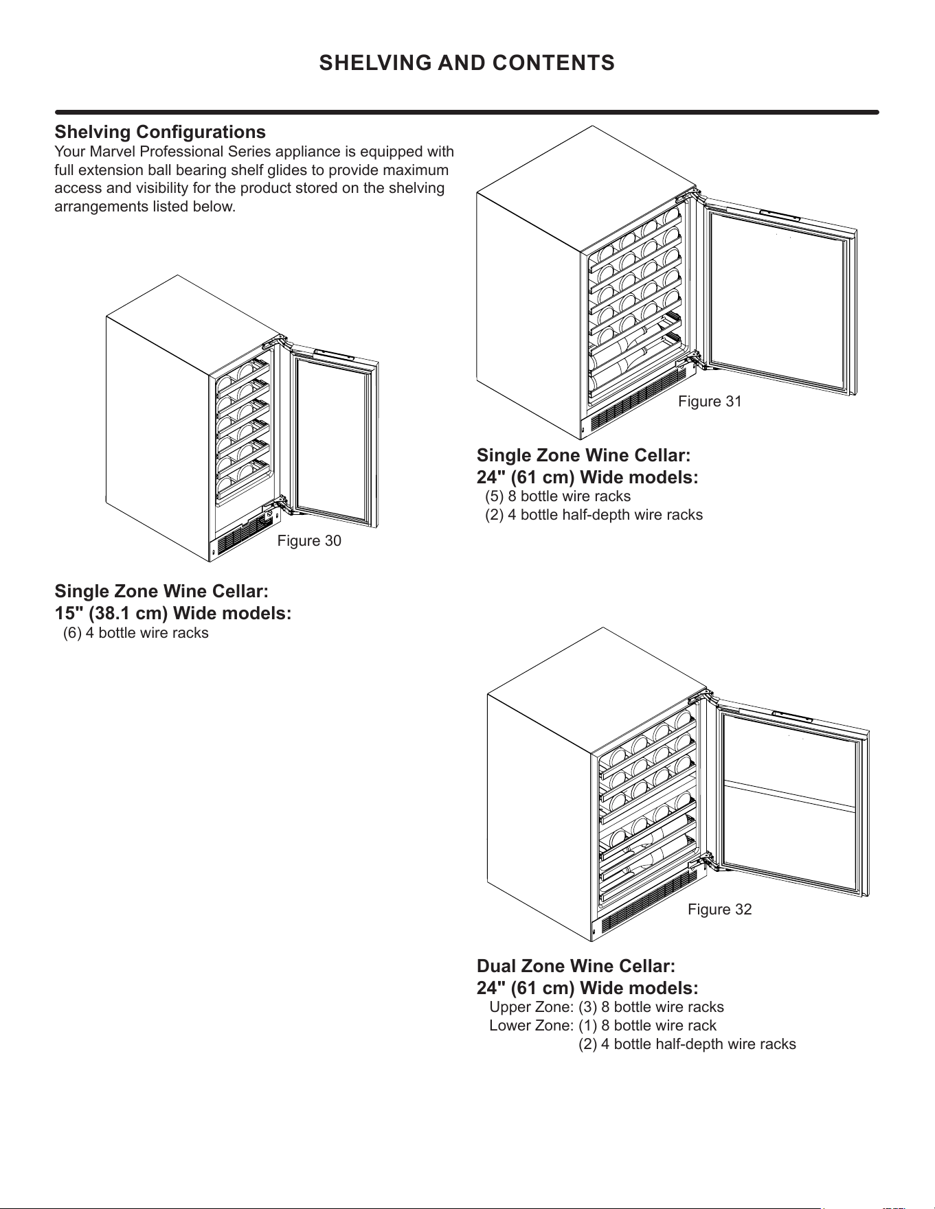
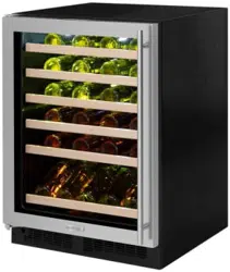
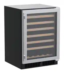
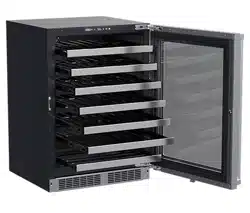
SHELVING AND CONTENTS
Shelving Congurations
Your Marvel Professional Series appliance is equipped with
full extension ball bearing shelf glides to provide maximum
access and visibility for the product stored on the shelving
arrangements listed below.
Dual Zone Wine Cellar:
24" (61 cm) Wide models:
Upper Zone: (3) 8 bottle wire racks
Lower Zone: (1) 8 bottle wire rack
(2) 4 bottle half-depth wire racks
Single Zone Wine Cellar:
24" (61 cm) Wide models:
(5) 8 bottle wire racks
(2) 4 bottle half-depth wire racks
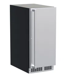
Single Zone Wine Cellar:
15" (38.1 cm) Wide models:
(6) 4 bottle wire racks
Figure 30
Figure 32
Figure 31
15
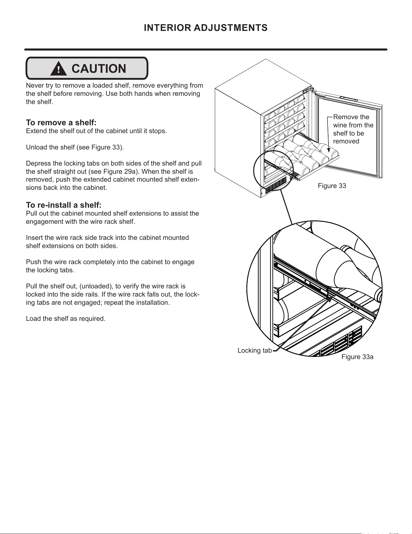
INTERIOR ADJUSTMENTS
Figure 33
Figure 33a
!
CAUTION
Never try to remove a loaded shelf, remove everything from
the shelf before removing. Use both hands when removing
the shelf.
To remove a shelf:
Extend the shelf out of the cabinet until it stops.
Unload the shelf (see Figure 33).
Depress the locking tabs on both sides of the shelf and pull
the shelf straight out (see Figure 29a). When the shelf is
removed, push the extended cabinet mounted shelf exten-
sions back into the cabinet.
To re-install a shelf:
Pull out the cabinet mounted shelf extensions to assist the
engagement with the wire rack shelf.
Insert the wire rack side track into the cabinet mounted
shelf extensions on both sides.
Push the wire rack completely into the cabinet to engage
the locking tabs.
Pull the shelf out, (unloaded), to verify the wire rack is
locked into the side rails. If the wire rack falls out, the lock-
ing tabs are not engaged; repeat the installation.
Load the shelf as required.
Locking tab
Remove the
wine from the
shelf to be
removed
16
!
CAUTION
Front Grille
Be sure that nothing obstructs the required air ow open-
ings in front of the cabinet. At least once or twice a year,
brush or vacuum lint and dirt from the front grille area (see
page 8).
SHOCK HAZARD: Disconnect electrical power from the
appliance before cleaning with soap and water.
Cabinet
The painted cabinet can be washed with either a mild soap
and water and thoroughly rinsed with clear water. NEVER
use abrasive scouring cleaners.
Interior
Wash interior compartment with mild soap and water. Do
NOT use an abrasive cleaner, solvent, polish cleaner or
undiluted detergent.
Care of Appliance
1. Avoid leaning on the door, you may bend the door
hinges or tip the appliance.
2. Exercise caution when sweeping, vacuuming or mop-
ping near the front of the appliance. Damage to the
grille can occur.
3. Periodically clean the interior of the appliance as
needed.
4. Periodically check and/or clean the front grille as
needed.
In the Event of a Power Failure
If a power failure occurs, try to correct it as soon as pos-
sible. Minimize the number of door openings while the
power is o so as not to adversely aect the appliance's
temperature.
Light assembly replacement
All models use an LED to illuminate the interior of the ap-
pliance. This component is very reliable, but should it fail,
contact a qualied service technician for replacement of the
LED.
CARE AND CLEANING
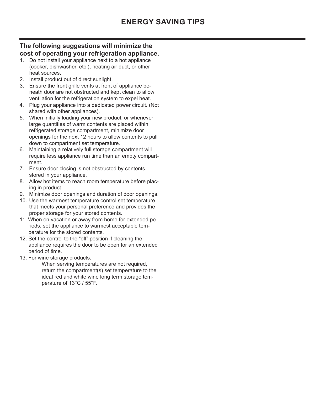
4. Plug your appliance into a dedicated power circuit. (Not
shared with other appliances).
5. When initially loading your new product, or whenever
large quantities of warm contents are placed within
refrigerated storage compartment, minimize door
openings for the next 12 hours to allow contents to pull
down to compartment set temperature.
6. Maintaining a relatively full storage compartment will
require less appliance run time than an empty compart-
ment.
7. Ensure door closing is not obstructed by contents
stored in your appliance.
8. Allow hot items to reach room temperature before plac-
ing in product.
9. Minimize door openings and duration of door openings.
10. Use the warmest temperature control set temperature
that meets your personal preference and provides the
proper storage for your stored contents.
11. When on vacation or away from home for extended pe-
riods, set the appliance to warmest acceptable tem-
perature for the stored contents.
12. Set the control to the “o” position if cleaning the
appliance requires the door to be open for an extended
period of time.
13. For wine storage products:
When serving temperatures are not required,
return the compartment(s) set temperature to the
ideal red and white wine long term storage tem-
perature of 13°C / 55°F.
The following suggestions will minimize the
cost of operating your refrigeration appliance.
1. Do not install your appliance next to a hot appliance
(cooker, dishwasher, etc.), heating air duct, or other
heat sources.
2. Install product out of direct sunlight.
3. Ensure the front grille vents at front of appliance be-
neath door are not obstructed and kept clean to allow
ventilation for the refrigeration system to expel heat.
17
ENERGY SAVING TIPS
4. Plug your appliance into a dedicated power circuit. (Not
shared with other appliances).
5. When initially loading your new product, or whenever
large quantities of warm contents are placed within
refrigerated storage compartment, minimize door
openings for the next 12 hours to allow contents to pull
down to compartment set temperature.
6. Maintaining a relatively full storage compartment will
require less appliance run time than an empty compart-
ment.
7. Ensure door closing is not obstructed by contents
stored in your appliance.
8. Allow hot items to reach room temperature before plac-
ing in product.
9. Minimize door openings and duration of door openings.
10. Use the warmest temperature control set temperature
that meets your personal preference and provides the
proper storage for your stored contents.
11. When on vacation or away from home for extended pe-
riods, set the appliance to warmest acceptable tem-
perature for the stored contents.
12. Set the control to the “o” position if cleaning the
appliance requires the door to be open for an extended
period of time.
13. For wine storage products:
When serving temperatures are not required,
return the compartment(s) set temperature to the
ideal red and white wine long term storage tem-
perature of 13°C / 55°F.
The following suggestions will minimize the
cost of operating your refrigeration appliance.
1. Do not install your appliance next to a hot appliance
(cooker, dishwasher, etc.), heating air duct, or other
heat sources.
2. Install product out of direct sunlight.
3. Ensure the front grille vents at front of appliance be-
neath door are not obstructed and kept clean to allow
ventilation for the refrigeration system to expel heat.
18
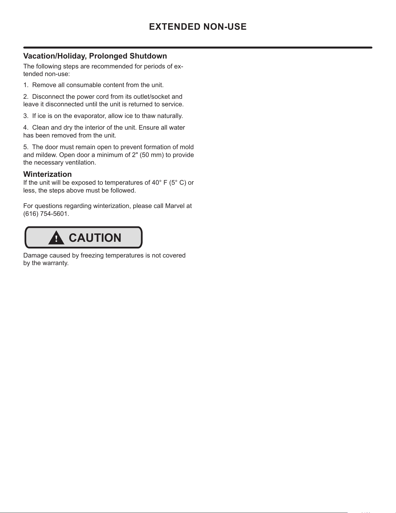
Vacation/Holiday, Prolonged Shutdown
The following steps are recommended for periods of ex-
tended non-use:
EXTENDED NON-USE
1. Remove all consumable content from the unit.
2. Disconnect the power cord from its outlet/socket and
leave it disconnected until the unit is returned to service.
3. If ice is on the evaporator, allow ice to thaw naturally.
4. Clean and dry the interior of the unit. Ensure all water
has been removed from the unit.
5. The door must remain open to prevent formation of mold
and mildew. Open door a minimum of 2" (50 mm) to provide
the necessary ventilation.
Winterization
If the unit will be exposed to temperatures of 40° F (5° C) or
less, the steps above must be followed.
For questions regarding winterization, please call Marvel at
(616) 754-5601.
!
CAUTION
Damage caused by freezing temperatures is not covered
by the warranty.
19
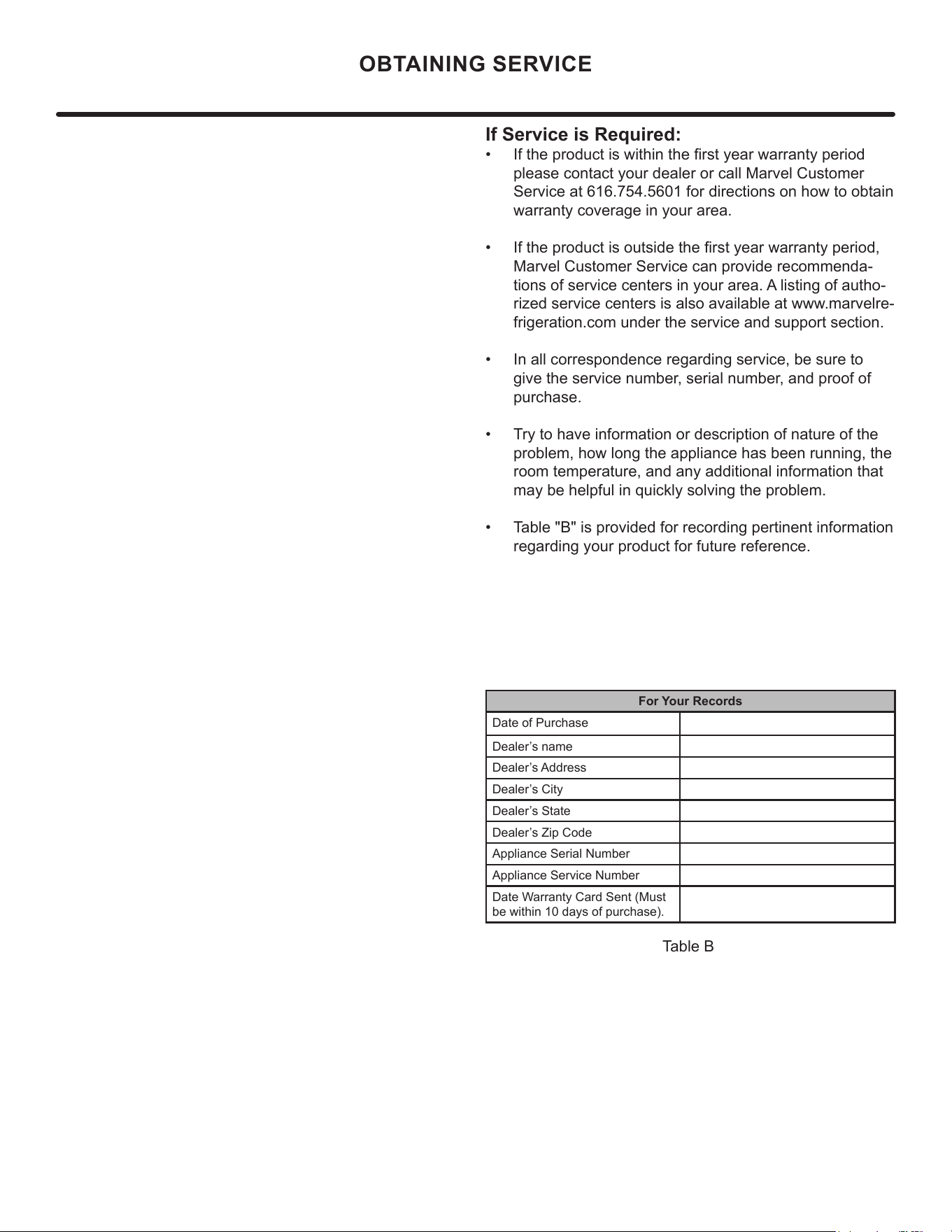
If Service is Required:
• If the product is within the rst year warranty period
please contact your dealer or call Marvel Customer
Service at 616.754.5601 for directions on how to obtain
warranty coverage in your area.
• If the product is outside the rst year warranty period,
Marvel Customer Service can provide recommenda-
tions of service centers in your area. A listing of autho-
rized service centers is also available at www.marvelre-
frigeration.com under the service and support section.
• In all correspondence regarding service, be sure to
give the service number, serial number, and proof of
purchase.
• Try to have information or description of nature of the
problem, how long the appliance has been running, the
room temperature, and any additional information that
may be helpful in quickly solving the problem.
• Table "B" is provided for recording pertinent information
regarding your product for future reference.
For Your Records
Date of Purchase
Dealer’s name
Dealer’s Address
Dealer’s City
Dealer’s State
Dealer’s Zip Code
Appliance Serial Number
Appliance Service Number
Date Warranty Card Sent (Must
be within 10 days of purchase).
Table B
OBTAINING SERVICE
20
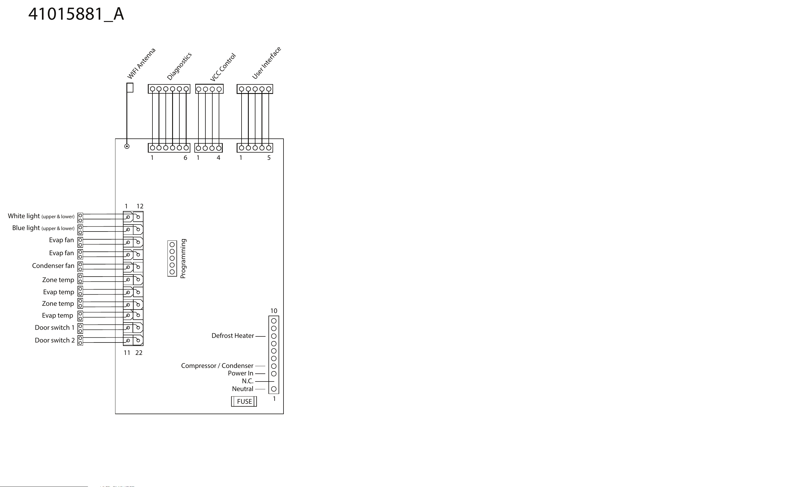
Power In
Compressor / Condenser
N.C.
Neutral
FUSE
11
10
22
1
1
12
White light
(upper & lower)
Blue light (upper & lower)
Evap fan
Evap fan
Condenser fan
Zone temp
Door switch 1
Door switch 2
Evap temp
Zone temp
Evap temp
Programming
WIFI Antenna
Diagnostics
VCC Control
User Interface
41015881_A
1 51 6 1 4
Defrost Heater
21
Ordering Replacement Parts
Parts may be ordered online at
www.partsformarvel.com
O
r contact:
www.marvelrefrigeration.com
(Servicers choose
"
Login
"
for
service account)
Phone Number: +1.
6
1
6
.754.5
6
01
NOTICE
Use only genuine
M
arvel replacement parts. The
use of non-
M
arvel parts can reduce performance,
damage the unit, and void the warranty.
Warranty parts will be shipped at no charge after
M
arvel
confirms warranty status. Please provide the model, serial
number, part number and part description. Some parts will
require color or voltage information.
If
M
arvel requires the return of original parts, we will
inform you when the parts order is taken. This
requirement will be noted on your packing list. A prepaid
shipping label will be emailed to you. Please enclose a
copy of the parts packing list and be sure the model and
serial numbers are legible on the paperwork. Tag the part
with the reported defect.
Customers and non-authorized servicers may order non
warranty parts at www.marvelrefrigeration.com.
Authorized servicers with a servicer login may order non-
warranty parts at www.marvelrefrigeration.m.
Ordering Replacement Parts
22
Ordering Replacement Parts
Parts may be ordered online at
www.partsformarvel.com
O
r contact:
www.marvelrefrigeration.com
(Servicers choose
"
Login
"
for
service account).
Phone Number: (
6
1
6
) 754-5
6
01
NOTICE
Use only genuine
M
arvel replacement parts. The
use of non-
M
arvel parts can reduce performance,
damage the unit, and void the warranty.
Warranty parts will be shipped at no charge after
M
arvel
confirms warranty status. Please provide the model, serial
number, part number and part description. Some parts will
require color or voltage information.
M
arvel requires the return of original parts, we will inform
you when the parts order is taken. This requirement will
be noted on your packing list. A prepaid shipping label will
be emailed to you. Please enclose a copy of the parts
packing list and be sure the model and serial numbers are
legible on the paperwork. Tag the part with the reported
defect.
Customers and non-authorized servicers may order non
warranty parts at www.partsformarvel.com. Authorized
servicers with a servicer login may order non-warranty
parts at www.marvelrefrigeration.m.
Ordering Replacement Parts
23
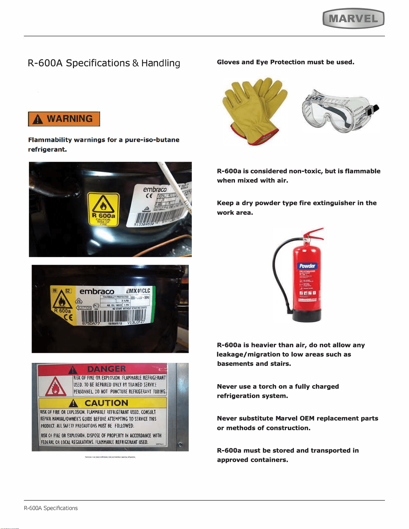
R-600A Specifications
&
H
an
dl
in
g
RISK Of FIRE OR EXPLOSION. FMMABLE REFRIGENT
USED. TO BE REPAIRED ONLY BY TINED SERVICE
PEONNEL DO HOT PUNURE REFRIGENT TUBING
SK Of FIRE OR EXPLOSION. FMHA_BLE REFRIGENT USED. CONSULT
REPAIR ANUAVOWHER'S GUIDE BEFORE AEMPTING TO SERVICE THIS
PRODU. ALL FE PREUONS HU BE FOUOWEO.
SK Of FIRE OR EXPLOSION. DISPOSE Of PROPER IN ACCORDANCE WITH
FEDE OR LOL REGUTIONS. FHHABLE REFRIGENT USED.
R-600A Specications
Gloves and Eye Protection must be used.
,
. ���·
'
R-600a is considered non-toxic, but is flammable
when mixed with air.
Keep a dry powder type fire extinguisher in the
work area.
R-600a is heavier than air, do not allow any
leakage/migration to low areas such as
basements and stairs.
Never use a torch on a fully charged
refrigeration system.
Never substitute Marvel OEM replacement parts
or methods of construction.
R-600a must be stored and transported in
approved containers.
24
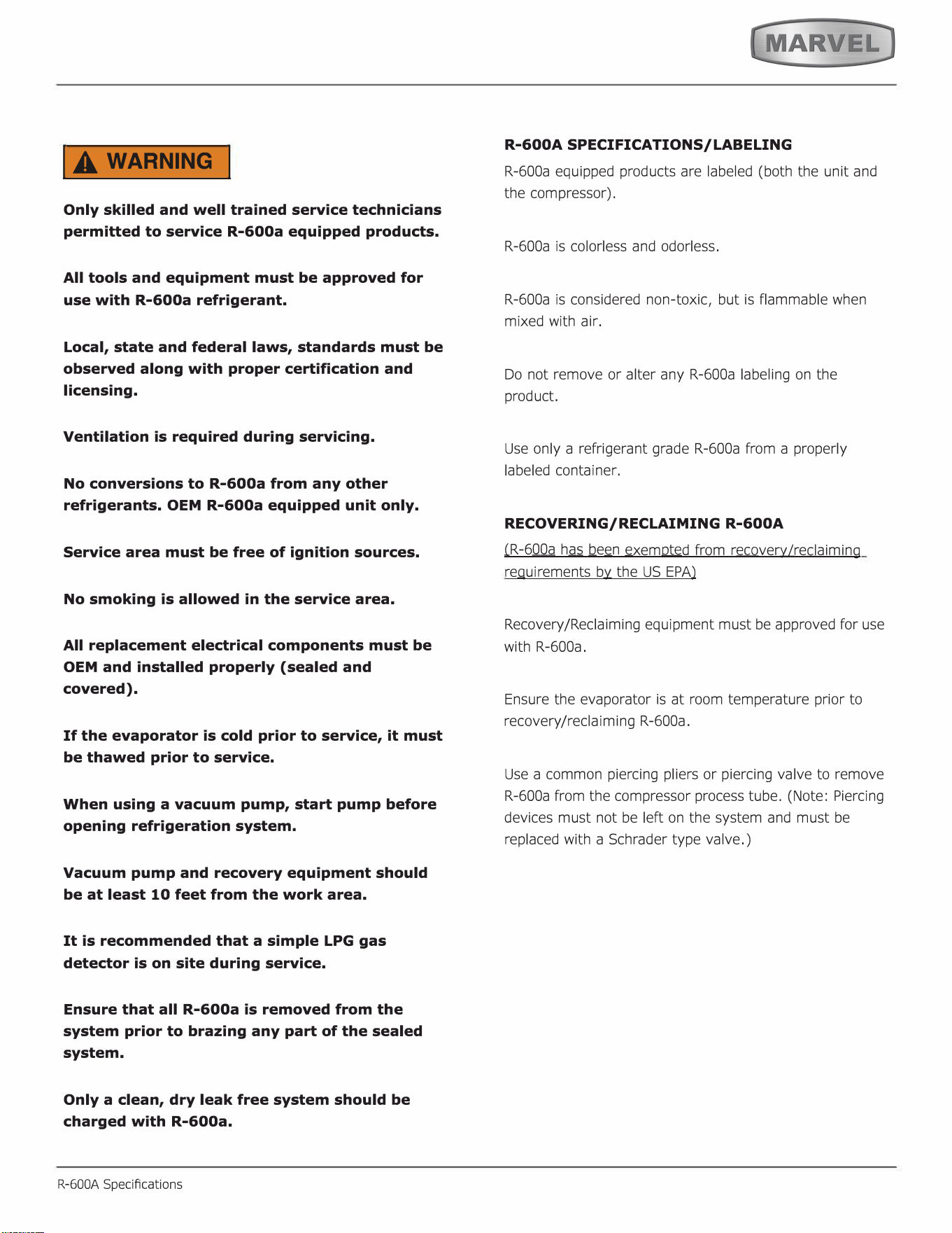
IA WARNING I
Only skilled and well trained service technicians
permitted to service R-600a equipped products.
All tools and equipment must be approved for
use with R-600a refrigerant.
Local, state and federal laws, standards must be
observed along with proper certification and
licensing.
Ventilation is required during servicing.
No conversions to R-600a from any other
refrigerants. OEM R-600a equipped unit only.
Service area must be free of ignition sources.
No smoking is allowed in the service area.
All replacement electrical components must be
OEM and installed properly (sealed and
covered).
If the evaporator is cold prior to service, it must
be thawed prior to service.
When using a vacuum pump, start pump before
opening refrigeration system.
Vacuum pump and recovery equipment should
be at least 10 feet from the work area.
It is recommended that a simple LPG gas
detector is on site during service.
Ensure that all R-600a is removed from the
system prior to brazing any part of the sealed
system.
Only a clean, dry leak free system should be
charged with R-600a.
R-600A Specications
R-600A SPECIFICATIONS/LABELING
R-600a equipped products are labeled (both the unit and
the compressor).
R-600a is colorless and odorless.
R-600a is considered non-toxic, but is flammable when
mixed with air.
Do not remove or alter any R-600a labeling on the
product.
Use only a refrigerant grade R-600a from a properly
labeled container.
RECOVERING/RECLAIMING R-600A
(
R-6
00a
h
as b
e
e
n
exempted from revery/reaiming
requirements by the US EPA)
Recovery/Reclaiming equipment must be approved for use
with R-600a.
Ensure the evaporator is at room temperature prior to
recovery /reclaiming R-600a.
Use a common piercing pliers or piercing valve to remove
R-600a from the compressor process tube. (Note: Piercing
devices must not be le on the system and must be
replaced with a Schrader type valve.)
25
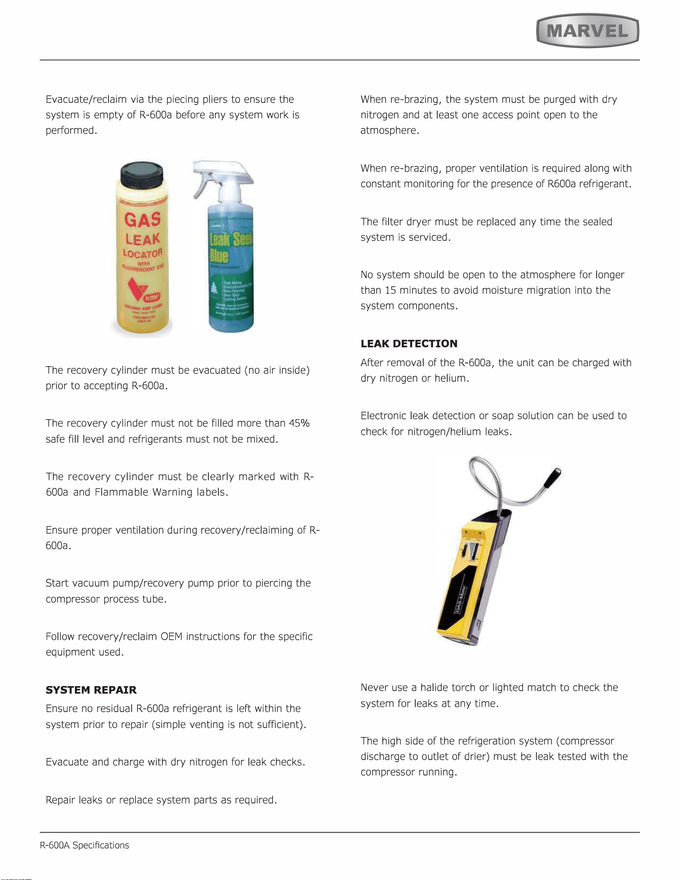
Evacuate/reclaim via the piecing pliers to ensure the
system is empty of R-600a before any system work is
performed.
GAS
LEA
LOCATO
The recovery cylinder must be evacuated (no air inside)
prior to accepting R-600a.
The recovery cylinder must not be filled more than 45%
safe fill level and refrigerants must not be mixed.
The recovery cylinder must be clearly marked with R-
600a and Flammable Warning labels.
Ensure proper ventilation during recovery/reclaiming of R-
600a.
Start vacuum pump/recovery pump prior to piercing the
compressor process tube.
Follow recovery/reclaim OEM instructions for the specific
equipment used.
SYSTEM REPAIR
Ensure no residual R-600a refrigerant is left within the
system prior to repair (simple venting is not sufficient).
Evacuate and charge with dry nitrogen for leak checks.
Repair leaks or replace system parts as required.
R-600A Specications
When re-brazing, the system must be purged with dry
nitrogen and at least one access point open to the
atmosphere.
When re-brazing, proper ventilation is required along with
constant monitoring for the presence of R600a refrigerant.
The filter dryer must be replaced any time the sealed
system is serviced.
No system should be open to the atmosphere for longer
than 15 minutes to avoid moisture migration into the
system components.
LEAK DETECTION
After removal of the R-600a, the unit can be charged with
dry nitrogen or helium.
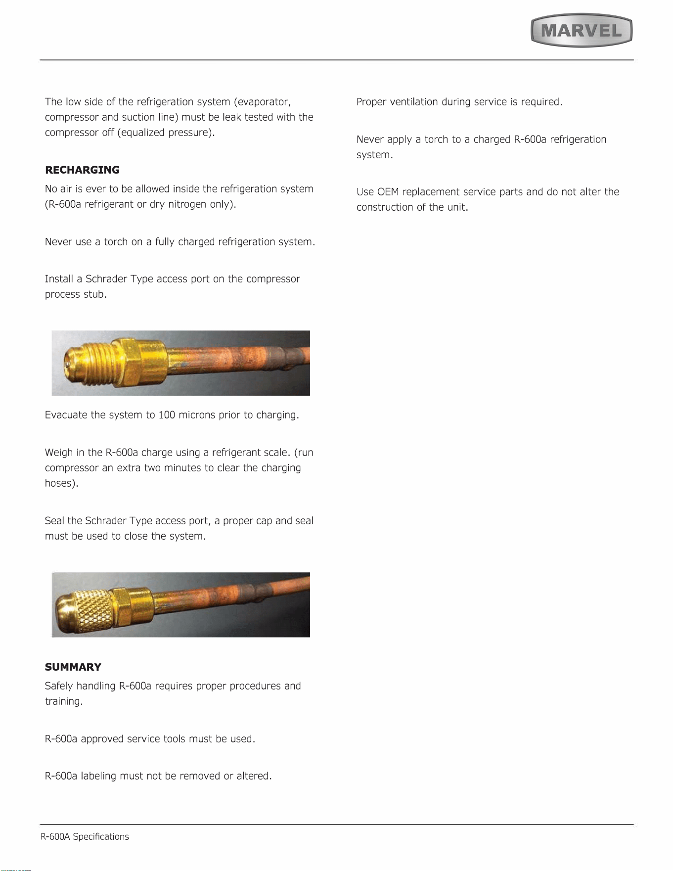
Electronic leak detection or soap solution can be used to
check for nitrogen/helium leaks.
Never use a halide torch or lighted match to check the
system for leaks at any time.
The high side of the refrigeration system (compressor
discharge to outlet of drier) must be leak tested with the
compressor running.
26
The low side of the refrigeration system (evaporator,
compressor and suction line) must be leak tested with the
compressor off (equalized pressure).
RECHARGING
No air is ever to be allowed inside the refrigeration system
(R-600a refrigerant or dry nitrogen only).
Never use a torch on a fully charged refrigeration system.
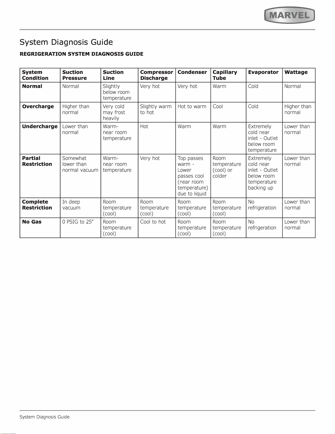
Install a Schrader Type access port on the compressor
process stub.
Evacuate the system to 100 microns prior to charging.
Weigh in the R-600a charge using a refrigerant scale. (run
compressor an extra two minutes to clear the charging
hoses).
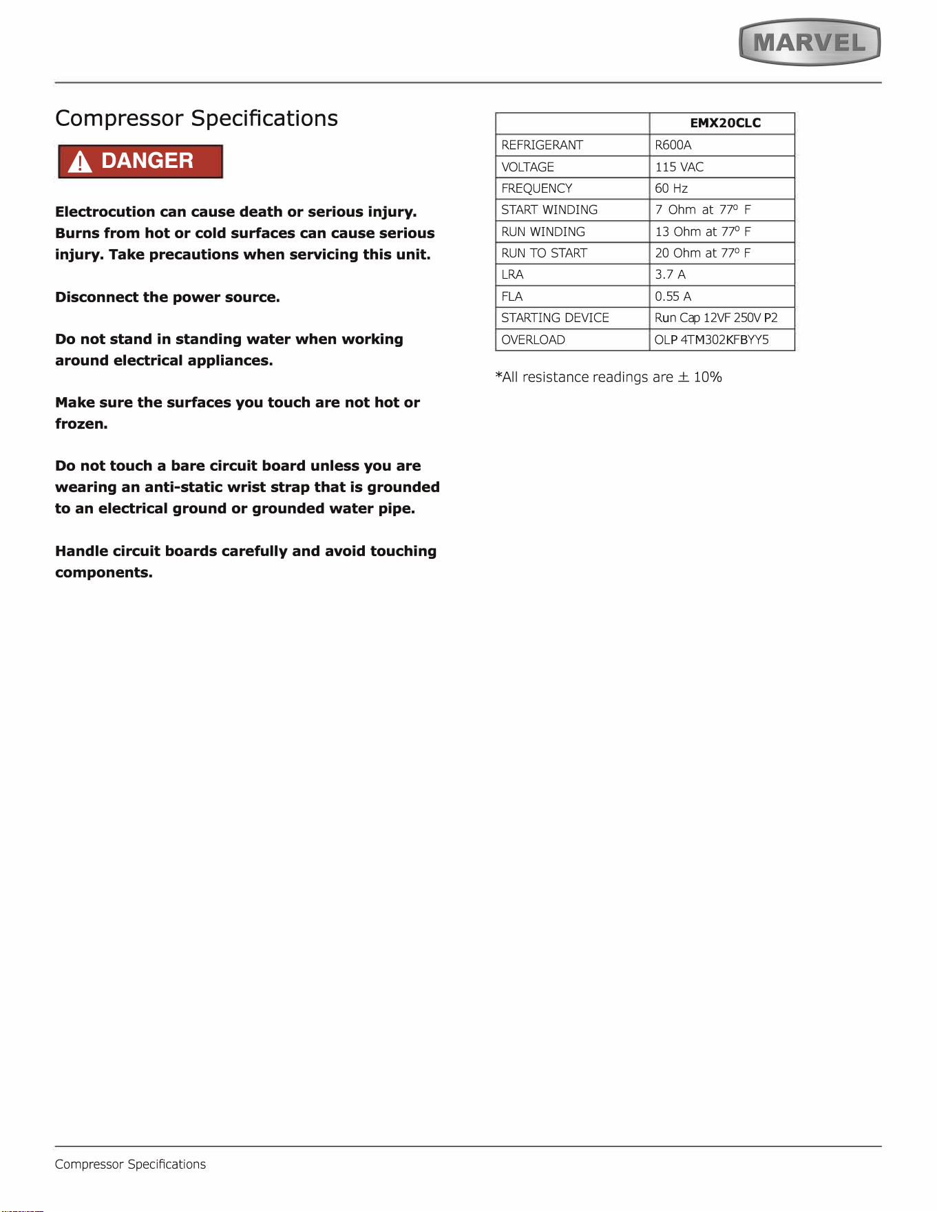
Seal the Schrader Type access port, a proper cap and seal
must be used to close the system.
SUMMARY
Safely handling R-600a requires proper procedures and
training.
R-600a approved service tools must be used.
R-600a labeling must not be removed or altered.
R-600A Specications
Proper ventilation during service is required.
Never apply a torch to a charged R-600a refrigeration
system.
Use OEM replacement service parts and do not alter the
construction of the unit.
27
System Diagnosis Guide
REGRIGERATION SYSTEM DIAGNOSIS GUIDE
System
Suction Suction
Compressor
Condition
Pressure
Line
Discharge
Normal Normal Slightly
Very hot
below room
temperature
Overcharge
Higher than
Very cold
Slightly warm
normal
may frost
to hot
heavily
Undercharge
Lower than
Warm- Hot
normal near room
temperature
Partial
Somewhat Warm-
Very hot
Restriction
lower than
near room
normal vacuum
temperature
Complete
In deep
Room Room
Restriction
vacuum
temperature temperature
(cool) (cool)
No Gas
0 PSIG to 25" Room
Cool to hot
temperature
(cool)
System Diagnosis Guide
Condenser
Capillary
Evaporator
Wattage
Tube
Very hot
Warm Cold Normal
Hot to warm
Cool
Cold
Higher than
normal
Warm Warm
Extremely Lower than
cold near
normal
inlet - Outlet
below room
temperature
Top passes
Room
Extremely Lower than
warm -
temperature
cold near
normal
Lower
(cool) or
inlet - Outlet
passes cool
colder
below room
(near room
temperature
temperature)
backing up
due to liquid
Room Room No
Lower than
temperature temperature refrigeration
normal
( cool) (cool)
Room Room No
Lower than
temperature temperature refrigeration
normal
( cool) (cool)
28
Compressor Specifications
A DANGER
Electrocution can cause death or serious injury.
Burns from hot or cold surfaces can cause serious
injury. Take precautions when servicing this unit.
Disconnect the power source.
Do not stand in standing water when working
around electrical appliances.
Make sure the surfaces you touch are not hot or
frozen.
Do not touch a bare circuit board unless you are
wearing an anti-static wrist strap that is grounded
to an electrical ground or grounded water pipe.
Handle circuit boards carefully and avoid touching
components.
Compressor SpeciAcations
E
MX
20
C
L
C
REFRIGERANT
R600A
VOLTAGE
115 VAC
FREQUENCY
60 Hz
STA WINDING
RUN WINDING
RUN TO S
7 Ohm at 77
°
F
13 Ohm at 77
°
F
20 Ohm at 77
°
F
LRA
FLA
3.7 A
0.55 A
STARTING DEVICE
OVERLOAD
R
u
n Cap 12VF 250V
P
2
O
L
P
4T
M
302
K
F
B
YY5
*All resistance readings are ± 10%
29
Troubleshooting - Ex
tended
I A
CAUTION
Never attempt to repair or perform maintenance
on the unit until the main electrical power has
been disconnected from the unit.
SPECIFIC ERRORS AND ISSUES
The advanced diagnostic capabilities of the electronic
controls allows r easy and thorough troubleshooting.
Navigation of the control is the key and is explained in
the CONTROL OPERATION section of the manual, along
with control button layout, control function descriptions,
a service mode menu and service menu selection
explanations.
Verification of temperature and thermistor performance can
be identified by directly viewing thermistor readings in the
service mode.
Included in this section are some diagnostic tips and of
course, if additional help is required, please contact the
M
arvel, "Customer Care Facility" at +1.
6
1
6
.754.5
6
01 for
assistance.
Troubleshooting Extended
NORMAL OPERATING SOUNDS
All models incorporate rigid am insulated cabinets to
provide high thermal efciency and maximum sound
reduction for its internal working components. Despite
this technology, your model may make sounds that are
unfamiliar.
Normal operating sounds may be more noticeable because
of the unit's environment. Hard surfaces such as cabinets,
wood, vinyl or tiled oors and paneled walls have a
tendency to reflect normal appliance operating noises.
Listed below are common refrigeration components with a
brief description of the normal sounds they make. NOTE:
Your product may not contain all the components listed.
•
•
•
•
Compressor: The compressor makes a hum or pulsing
sound that may be heard when it operates.
Evaporator: Refrigerant flowing through an evaporator
may sound like boiling liquid.
Condenser Fan: Air moving through a condenser may
be heard.
Automatic Defrost Drain Pan: Water may be heard
dripping or running into the drain pan when the unit is
in the defrost cycle.
Solenoid Valves: An occasional clicking sound may be
heard as solenoid valves are operated.
30
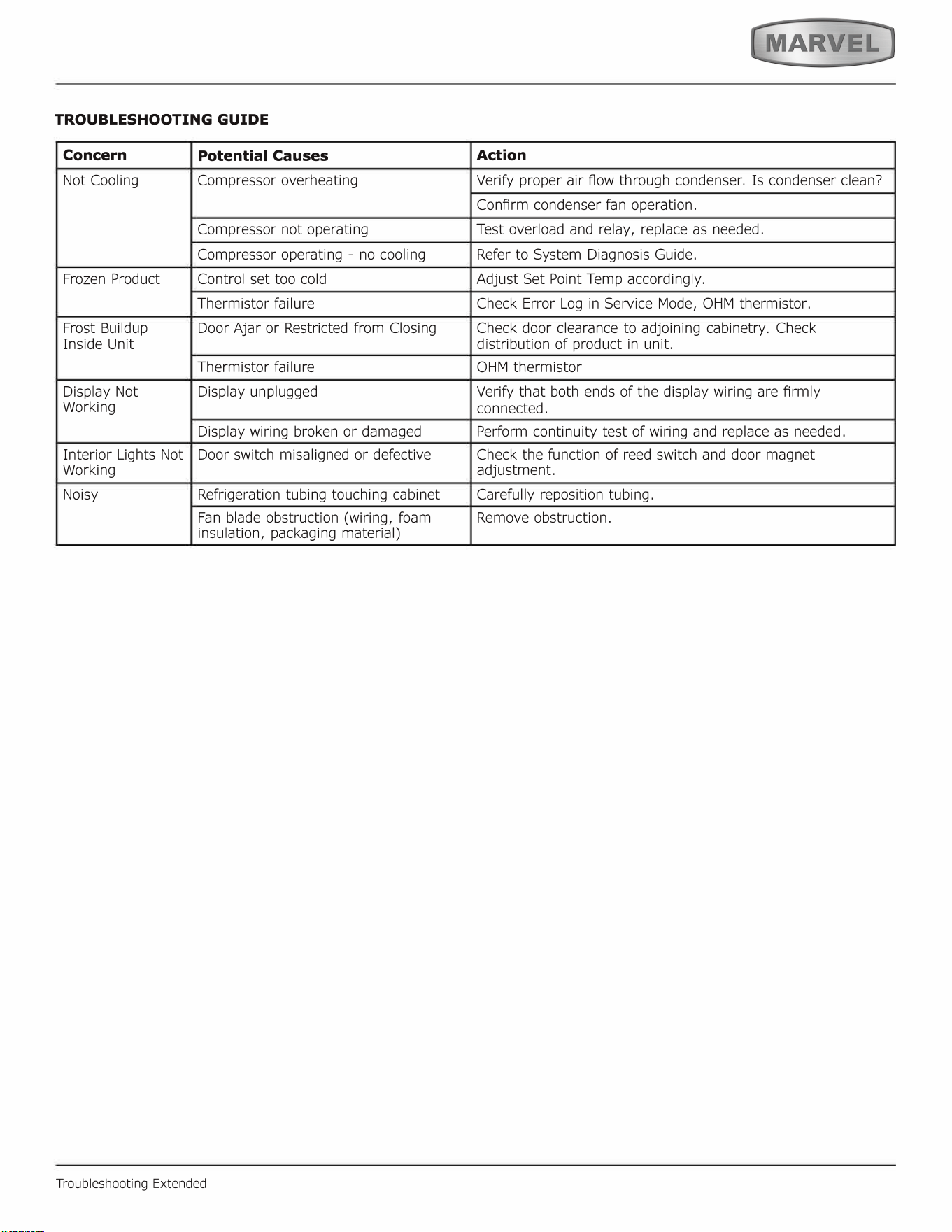
TROUBLESHOOTING GUIDE
Concern
Potential Causes
Action
Not Cooling
Compressor overheating
Verify proper air Aow through condenser. Is condenser clean?
Conrm condenser fan operation.
Compressor not operating
Test overload and relay, replace as needed.
Compressor operating - no cooling Refer to System Diagnosis Guide.
Frozen Product
Control set too cold
Adjust Set Point Temp accordingly.
Thermistor failure Check Error Log in Service Mode, OHM thermistor.
Frost Buildup Door ar or Restricted from Closing
Check door clearance to adjoining cabinetry. Check
Inside Unit distribution of product in unit.
Thermistor failure
OHM thermistor
Display Not
Display unplugged
Verify that both ends of the display wiring are rmly
Working
connected.
Display wiring broken or damaged
Perform continuity test of wiring and replace as needed.
Interior Lights Not
Door switch misaligned or defective
Check the function of reed switch and door magnet
Working
adjustment.
Noisy Refrigeration tubing touching cabinet Carefully reposition tubing.
Fan blade obstruction (wiring, foam
Remove obstruction.
insulation, packaging material)
Troubleshooting Extended
31
MAIN CONTROL
The main control board is very robust and is rarely the
cause of system issues. It is important to fully diagnose
the board for any suspected failures before attempting
to remove the board for replacement or service. Follow
the guidelines below to fully test and diagnose the main
control.
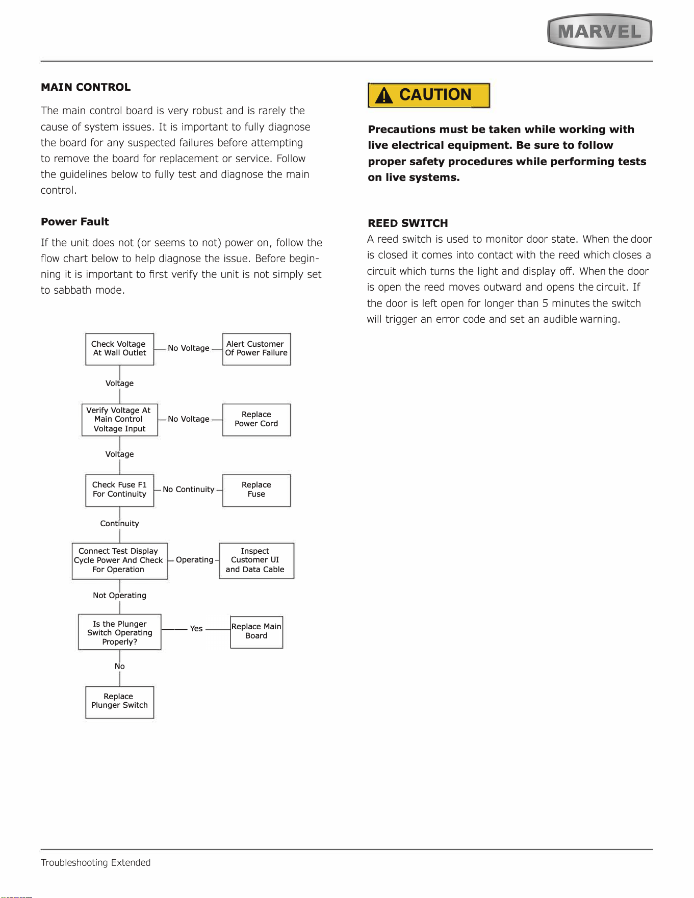
Power Fault
If the unit does not (or seems to not) power on, follow the
flow chart below to help diagnose the issue. Before begin
ning it is important to rst verify the unit is not simply set
to sabbath mode.
Check Voltage
At Wall Outlet
Voltage
Verify Voltage At
No Voltage
Main Control No Voltage
Voltage Input
Voltage
Check Fuse Fl
For Continuity
Continuity
No Continuity
Alert Customer
Of Power Failure
Replace
Power Cord
Replace
Fuse
Inspect
Connect Test Display
Cycle Power And Check
For Operation
Operating - Customer UI
Not Operating
Is the Plunger __
Yes
Switch Operating
Properly?
No
Replace
Plunger Switch
Troubleshooting Extended
and Data Cable
Replace Main
Board
I A
CAUTION
Precautions must be taken while working with
live electrical equipment. Be sure to follow
proper safety procedures while performing tests
on live systems.
REE
D
SWITCH
A reed switch is used to monitor door state. When the door
is closed it comes into contact with the reed which closes a
circuit which turns the light and display o. When the door
is open the reed moves outward and opens the circuit. If
the door is left open for longer than 5 minutes the switch
will trigger an error code and set an audible warning.
32
Control Operation-Service
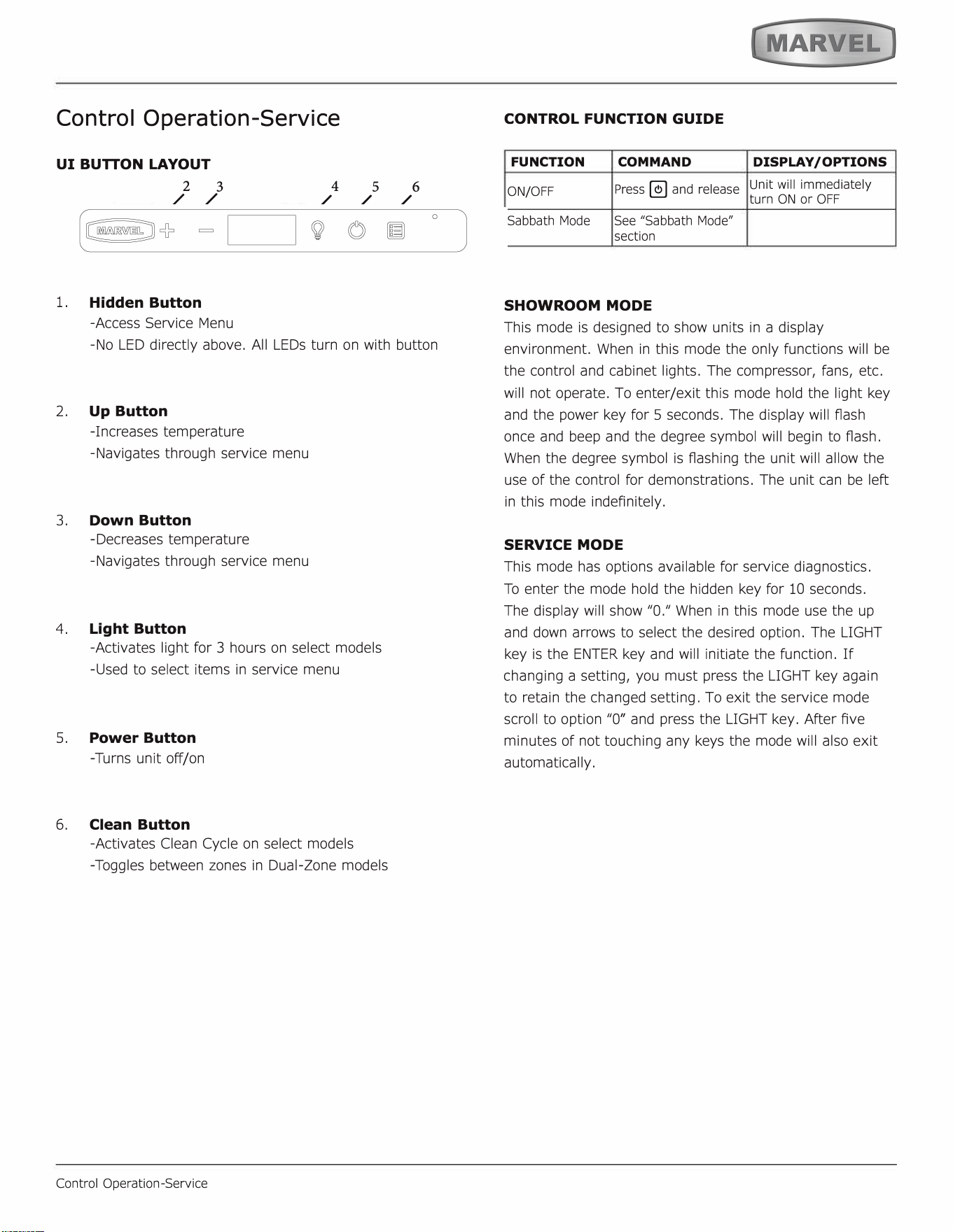
UI BUON LAYOUT
2
3
/ /
1.
Hidden Button
-Access Service Menu
4
5 6
/ / /
-No LED directly above. All LEDs turn on with button
2. Up Button
-Increases temperature
-Navigates through service menu
3.
Down Button
-Decreases temperature
-Navigates through service menu
4. Light Button
-Activates light r 3 hours on select models
-Used to select items in service menu
5.
Power Button
-Turns unit o/on
6.
Clean Button
-Activates Clean Cycle on select models
-Toggles between zones in Dual-Zone models
Control Operation-Service
CONTROL FUNCTION GUIDE
FUNCTION COMMAND
DISPLAY/ OPTIONS
ON/OFF
Press � and release
Unit will immediately
turn ON or OFF
Sabbath Mode See "Sabbath Mode"
section
SHOWROOM MODE
This mode is designed to show units in a display
environment. When in this mode the only functions will be
the control and cabinet lights. The compressor, fans, etc.
will not operate. To enter/exit this mode hold the light key
and the power key for 5 seconds. The display will f1ash
once and beep and the degree symbol will begin to ash.
When the degree symbol is ashing the unit will allow the
use of the control for demonstrations. The unit can be le�
in this mode indefinitely.
SERVICE MODE
This mode has options available for service diagnostics.
To enter the mode hold the hidden key for 10 seconds.
The display will show "O." When in this mode use the up
and down arrows to select the desired option. The LIGHT
key is the ENTER key and will initiate the function. If
changing a setting, you must press the LIGHT key again
to retain the changed setting. To exit the service mode
scroll to option "O" and press the LIGHT key. After Ave
minutes of not touching any keys the mode will also exit
automatically.
33
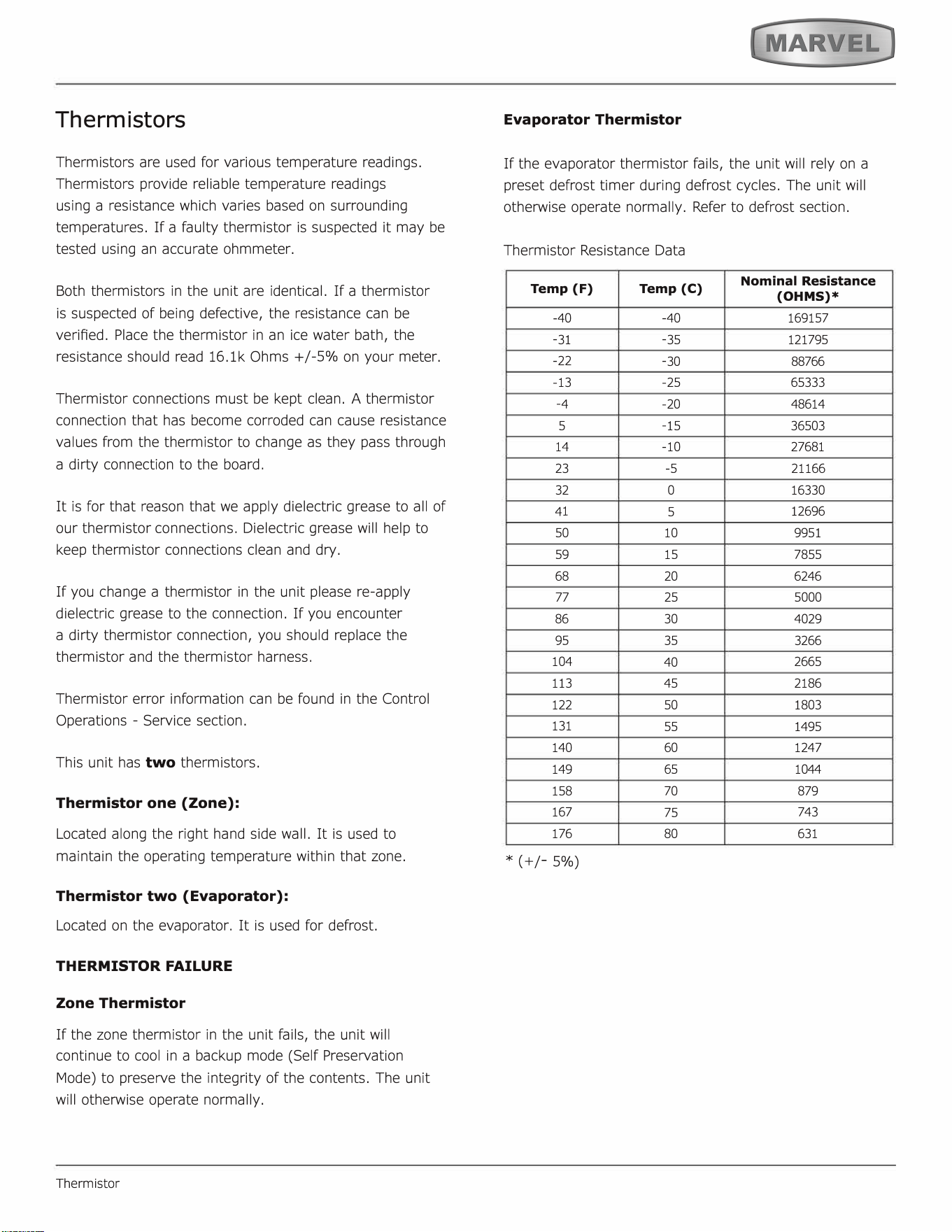
Thermistors
Thermistors are used for various temperature readings.
Thermistors provide reliable temperature readings
using a resistance which varies based on surrounding
temperatures. If a faulty thermistor is suspected it may be
tested using an accurate ohmmeter.
Both thermistors in the unit are identical. If a thermistor
is suspected of being defective, the resistance can be
veried. Place the thermistor in an ice water bath, the
resistance should read 16.lk Ohms +/-5% on your meter.
Thermistor connections must be kept clean. A thermistor
connection that has become corroded can cause resistance
values from the thermistor to change as they pass through
a dirty connection to the board.
It is for that reason that we apply dielectric grease to all of
our thermistor connections. Dielectric grease will help to
keep thermistor connections clean and dry.
If you change a thermistor in the unit please re-apply
dielectric grease to the connection. If you encounter
a dirty thermistor connection, you should replace the
thermistor and the thermistor harness.
Thermistor error information can be found in the Control
Operations - Service section.
This unit has two thermistors.
Thermistor one (Zone):
Located along the right hand side wall. It is used to
maintain the operating temperature within that zone.
Thermistor two (Evaporator):
Located on the evaporator. It is used for defrost.
THERMISTOR FAILURE
Zone Thermistor
If the zone thermistor in the unit fails, the unit will
continue to cool in a backup mode
(
Self Preservation
Mode) to preserve the integrity of the contents. The unit
will otherwise operate normally.
Thermistor
Evaporator Thermistor
If the evaporator thermistor fails, the unit will rely on a
preset defrost timer during defrost cycles. The unit will
otherwise operate normally. Refer to defrost section.
Thermistor Resistance Data
Temp (F)
Temp (C)
Nominal Resistance
(OHMS)*
-
40
-
40
169157
-
31
-
35
121795
-
22
-
30
88766
-
13
-
25 65333
-
4
-
20
48614
5
-
15
36503
14
-
10 27681
23
-
5
21166
32
0
16330
41
5
12696
50
10
9951
59
15
7855
68
20 6246
77
25
5000
86 30
4029
95
35
3266
104
40
2665
113
45
2186
122
50
1803
131
55
1495
140
60
1247
149
65
1044
158
70 879
167
75
743
176
80
631
*
(
+/-5%)
34
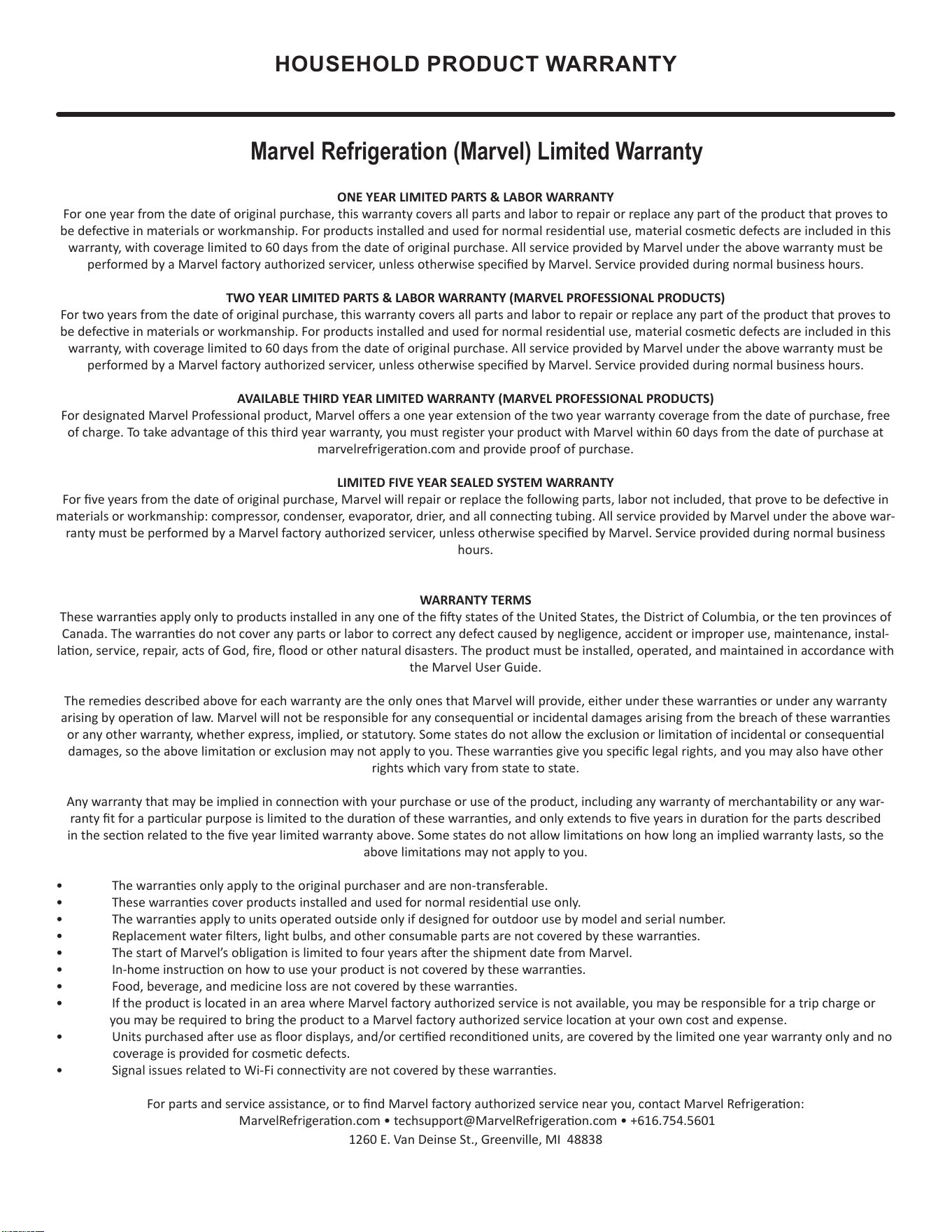
HOUSEHOLD PRODUCT WARRANTY
Marvel Refrigeration (Marvel) Limited Warranty
ONE YEAR LIMITED PARTS & LABOR WARRANTY
For one year from the date of original purchase, this warranty covers all parts and labor to repair or replace any part of the product that proves to
be defecve in materials or workmanship. For products installed and used for normal residenal use, material cosmec defects are included in this
warranty, with coverage limited to 60 days from the date of original purchase. All service provided by Marvel under the above warranty must be
performed by a Marvel factory authorized servicer, unless otherwise specied by Marvel. Service provided during normal business hours.
TWO YEAR LIMITED PARTS & LABOR WARRANTY (MARVEL PROFESSIONAL PRODUCTS)
For two years from the date of original purchase, this warranty covers all parts and labor to repair or replace any part of the product that proves to
be defecve in materials or workmanship. For products installed and used for normal residenal use, material cosmec defects are included in this
warranty, with coverage limited to 60 days from the date of original purchase. All service provided by Marvel under the above warranty must be
performed by a Marvel factory authorized servicer, unless otherwise specied by Marvel. Service provided during normal business hours.
AVAILABLE THIRD YEAR LIMITED WARRANTY (MARVEL PROFESSIONAL PRODUCTS)
For designated Marvel Professional product, Marvel oers a one year extension of the two year warranty coverage from the date of purchase, free
of charge. To take advantage of this third year warranty, you must register your product with Marvel within 60 days from the date of purchase at
marvelrefrigeraon.com and provide proof of purchase.
LIMITED FIVE YEAR SEALED SYSTEM WARRANTY
For ve years from the date of original purchase, Marvel will repair or replace the following parts, labor not included, that prove to be defecve in
materials or workmanship: compressor, condenser, evaporator, drier, and all connecng tubing. All service provided by Marvel under the above war-
ranty must be performed by a Marvel factory authorized servicer, unless otherwise specied by Marvel. Service provided during normal business
hours.
WARRANTY TERMS
These warranes apply only to products installed in any one of the y states of the United States, the District of Columbia, or the ten provinces of
Canada. The warranes do not cover any parts or labor to correct any defect caused by negligence, accident or improper use, maintenance, instal-
laon, service, repair, acts of God, re, ood or other natural disasters. The product must be installed, operated, and maintained in accordance with
the Marvel User Guide.
The remedies described above for each warranty are the only ones that Marvel will provide, either under these warranes or under any warranty
arising by operaon of law. Marvel will not be responsible for any consequenal or incidental damages arising from the breach of these warranes
or any other warranty, whether express, implied, or statutory. Some states do not allow the exclusion or limitaon of incidental or consequenal
damages, so the above limitaon or exclusion may not apply to you. These warranes give you specic legal rights, and you may also have other
rights which vary from state to state.
Any warranty that may be implied in connecon with your purchase or use of the product, including any warranty of merchantability or any war-
ranty t for a parcular purpose is limited to the duraon of these warranes, and only extends to ve years in duraon for the parts described
in the secon related to the ve year limited warranty above. Some states do not allow limitaons on how long an implied warranty lasts, so the
above limitaons may not apply to you.
• The warranes only apply to the original purchaser and are non-transferable.
• These warranes cover products installed and used for normal residenal use only.
• The warranes apply to units operated outside only if designed for outdoor use by model and serial number.
• Replacement water lters, light bulbs, and other consumable parts are not covered by these warranes.
• The start of Marvel’s obligaon is limited to four years aer the shipment date from Marvel.
• In-home instrucon on how to use your product is not covered by these warranes.
• Food, beverage, and medicine loss are not covered by these warranes.
• If the product is located in an area where Marvel factory authorized service is not available, you may be responsible for a trip charge or
you may be required to bring the product to a Marvel factory authorized service locaon at your own cost and expense.
• Units purchased aer use as oor displays, and/or cered recondioned units, are covered by the limited one year warranty only and no
coverage is provided for cosmec defects.
• Signal issues related to Wi-Fi connecvity are not covered by these warranes.
For parts and service assistance, or to nd Marvel factory authorized service near you, contact Marvel Refrigeraon:
MarvelRefrigeraon.com • techsupport@MarvelRefrigeraon.com • +616.754.5601
1260 E. Van Deinse St., Greenville, MI 48838
35
Marvel Refrigeration
All specications and product designs subject to change without notice. Such revisions do not entitle
the buyer to corresponding changes, improvements, additions, replacements or compensation for
previously purchased products.
www.marvelrefrigeration.com
1260 E. Van Deinse St.
Greenville MI 48838
616.754.5601
41015884 Rev A
12/9/20
36