21
THE POWER OF PERFORMANCE™
USE AND CARE / INSTALLATION GUIDE
PERFORMANCE SERIES VENT HOOD
Models:
PSVH24
PSVH30
PSVH36
PSVH36HL
PSVH48
PSVH48HL
PSVH60
PSVH60HL

1
A SPECIAL MESSAGE TO OUR CUSTOMERS
Dear Valued Customer,
Congratulations on making a smart choice! You have joined an elite group of cooking enthusiasts
who demand only the very best from their appliances. A Capital Cooking appliance promises years
of enjoyment and maximum pleasure, allowing cooks everywhere to create culinary memories that
last a lifetime.
Because of the unique features found in our appliances, we urge you to read this manual thoroughly
before installation and use. And please RETAIN THIS MANUAL FOR FUTURE REFERENCE: it is
an invaluable guide to help you better understand your Capital Cooking appliance.
Since your satisfaction is our topmost priority, please feel free to contact our service experts. You
may reach us toll free at 866-402-4600, or dial the factory direct at 562-903-1168. You can fax us a
list of your concerns, comments, and/or compliments at 562-903-1167, or drop us an email at
[email protected]. Feel free to also write us at 13211 East Florence Avenue,
Santa Fe Springs, CA 90670.
Our products are proudly designed and manufactured in America, and we trust that our strict
adherence to the highest quality assurance standards will provide you with years of troubled free,
gourmet cooking.
Happy Cooking!
Capital Cooking Test Kitchen Specialists

2
TABLE OF CONTENTS
USE AND CARE MANUAL........................................…………………………….…..…3-8
Installation Guide …………………………………………….…….............…….9
Service Information ……………………………………………………………….21
Warranty……………………………………………………………………….........22
Notes……………………………………………………………….……….….........25-26

APPROVED FOR INDOOR COOKING APPLIANCES AND INDOOR RESIDENTIAL
USE ONLY. NOT FOR COMMERCIAL USE!
Note: For Out-Door Use Call the Capital Sales Department
--READ AND SAVE THESE INSTRUCTIONS--
Installation must comply with all local codes.
WARNING: TO REDUCE THE RISK OF A RANGE TOP GREASE FIRE:
A. Never leave surface units unattended at high settings. Boil overs cause
smoking and greasy spillovers that may ignite. Heat oil slowly on low
Settings.
B. Always turn hood “ON” when cooking at high heat or when flambéing food (i.e. Crepes
Suzette, Cherries Jubilee, Peppercorn Beef Flambe).
C. Clean ventilating fans frequently. Grease should not be allowed to
accumulate on fan or filter.
D. Use proper pan size. Always use cookware appropriate for the size of
the surface element.
WARNING: TO REDUCE THE RISK OF INJURY TO PERSONS IN THE EVENT OF A
RANGE TOP GREASE FIRE, OBSERVE THE FOLLOWING:
A. SMOTHER FLAMES with a close-fitting lid, cookie sheet, or metal tray, then turn off
the burner. BE CAREFUL TO PREVENT BURNS. If the flames do not go out
immediately, EVACUATE AND CALL THE FIRE DEPARTMENT.
B. NEVER PICK UP A FLAMING PAN – You may be burned.
C. DO NOT USE WATER, including wet dishcloths or towels -- a violent steam
explosion will result.
D. Use and extinguisher ONLY if:
a. You know you have a Class ABC extinguisher, and you already know how to
operate it.
b. The fire is small and contained in the area where it started.
c. The fire department is being called
d. You can fight the fire with your back to an exit.
(Based on “Kitchen Fire Safety Tips” published by NFPA)
Note: Make-up air may be necessary to prevent air flowing down chimney, unsealed door,
window, or fireplace opening.
3

WARNING: TO REDUCE THE RISK OF FIRE, ELECTRIC SHOCK, OR INJURY TO
PERSONS, OBSERVE THE FOLLOWING:
A. Use this unit only in the manner intended by the manufacturer. If you have questions,
contact the manufacturer at 866-402-4600.
B. Before servicing or cleaning the unit, switch power off at service panel and lock the
service disconnecting means to prevent power from being switched on accidentally.
When the service disconnecting means cannot be locked, securely fasten a prominent
warning device, such as a tag, to the service panel.
C. Installation work and Electrical Wiring must be done by qualified person(s) in accordance
with all applicable codes and standards, including fire rated construction.
D. Sufficient air is needed for proper combustion and exhausting of gases through the flue
(chimney) of fuel burning equipment to prevent back drafting. Follow the heating
equipment manufacturer’s guideline and safety standards such as those published by the
National Fire Protection Association (NFPA), and the American Society for Heating,
Refrigeration and Air Conditioning Engineers (ASHRAE), and the local code authorities.
E. When cutting or drilling into wall or ceiling, do not damage electrical wiring and other
hidden utilities.
F. Ducted fans must always be vented to the outdoors.
CAUTION: Reduce the risk of fire and to properly exhaust air, be sure to duct air to
outside. Do not vent exhaust air into spaces within walls or ceiling, nor into attics, crawl
spaces, or garages.
Note: Unit must be vented to the outside of the building.
WARNING!: To reduce the risk of electrical shock or injury to persons, all Vent Hoods
must be installed with ventilators that have been approved for use with the hood.
WARNING! – If the information in this manual is not followed exactly, a fire or
explosion may result causing property damage, personal injury or death. Do not
store or use gasoline or other flammable vapors or liquids in the vicinity of this or
any other appliance.
SAFETY WARNING! – Turn off power circuit at service panel and lock out panel,
before wiring this appliance. Requirement: 120V AC, 60 HZ. 15 A Branch Circuit
FOR YOUR SAFETY!
If You Smell Gas:
• Do not try to light any appliance.
• Do not touch any electrical switch; do not use any phone in your
building.
• Immediately call your gas supplier from a neighbor’s phone. Follow
the gas supplier’s instructions.
• If you cannot reach your gas supplier, call the fire department.
• Installation and service must be performed by a qualified installer,
service agency or the gas supplier.
4

SAFETY PRACTICES AND PRECAUTIONS
CAUTION! – For general ventilation use only. DO NOT use to exhaust hazardous
or explosive materials or vapors.
CAUTION! – To reduce the risk of fire and to properly exhaust air, be sure to duct
air to outside. Do not vent exhaust air into spaces within walls or ceiling, nor into
attics, crawl spaces or garages.
WARNING! – To reduce the risk of fire, use only metal ductwork.
Install this hood in accordance with all requirements specified.
WARNING! – To reduce the risk of fire or electrical shock, do not use this hood with
any external solid-state speed control device.
This Vent Hood system is designed to remove smoke, cooking vapors and odors from the
cook top area.
WARNING! – All wall and floor openings where the vent hood is installed must be
sealed.
Consult the cook top or range installation instructions given by the manufacturer before
making any cutouts. MOBILE HOME INSTALLATION: the installation of this Hood
must conform to the Manufactured Home Construction and Safety Standards, Title 24
CFR, Part 3280 (Formerly Federal Standard for Mobile Home Construction and Safety,
Title 24, HUD, part 280). Three wire power supplies must be used and the appliance
wiring must be revised. See electrical requirements on page 1.
DO NOT use 4” laundry –type wall caps
Flexible-type ductwork is not recommended
DO NOT obstruct the flow of combustion and ventilation air. Be sure a fresh air
supply is available.
Failure to follow venting requirements may result in a fire.
Electrical ground is required on this hood.
If cold water pipe is interrupted by plastic, non-metallic gaskets or other
materials, DO NOT use for grounding.
DO NOT ground to gas pipe.
DO NOT have a fuse in the neutral or grounding circuit. A fuse in the neutral or
grounding circuit could result in electrical shock.
Check with a qualified electrician if you are in doubt as to whether the Hood is
properly grounded.
Failure to follow electrical requirements may result in a fire.
Be sure all the range and/or cook top controls are turned off and the appliance is
cool before using any type of aerosol cleaner on or around the appliance. The
chemical that produces the spraying action could, in the presence of heat, ignite or
cause metal parts to corrode.
5

Clean the ventilator hood and filters above the range or cook top frequently so
grease from cooking =vapors does not accumulate on them.
Service should only be done by authorized technicians; Technicians must
disconnect the power supply before servicing this appliance.
WARNING! – California proposition 65—the burning of gas cooking fuel generates
some by-products, which are known by the State of California to cause cancer or
reproductive harm. California law requires businesses to warn customers of
potential exposure to such substances. To minimize exposure to these substances,
always operate this unit according to the instructions contained in this booklet and
provide good ventilation to the room when cooking with gas.
PLEASE RETAIN THIS MANUAL FOR FUTURE
REFERENCE.
6

FAN CONTROL
Turn knob clockwise to desired position and intensity of fan speed as needed.
Continuous use of the fan system while cooking helps keep the kitchen comfortable and
less humid. It also reduces cooking odors and soiling moisture that create a frequent need
for cleaning.
ALWAYS USE THE MAXIMUM SETTING WHEN GRILLING.
LIGHT SWITCH
The Light Switch is colored Black. Turn on or off depending on need.
HEAT LAMPS
The Heat Lamps Switch is also colored Black. Turn on or off depending on need.
HOOD OPERATING INSTRUCTIONS
The blower should be turned on for a few minutes before cooking in order to establish air
currents upward through hood. Thus, when heat, smoke, moisture, grease, steam and
cooking odors are produced, they will be carried outside instead of drifting to other
rooms. Use the LOW speeds for normal use and the HIGHER speeds for strong odors
and fumes. Drafts across the range or cook top will prevent the proper escape of heat,
smoke, moisture, grease, steam and cooking odors into the hood. Such drafts should be
prevented in so far as possible. The best job of ventilation in the kitchen is done where
the only air currents are those created by the blower itself.
BLOWER
The motor is operated by an INFINITE fan speed setting control knob. You may change
the speed of the motor depending on the amount of grease, odor and smoke you create
while cooking.
FILTERS AND DRIP TRAYS
These hoods have reusable metal grease baffles and drip trays. The metal baffles channel
grease released by foods on the cook top into the drip trays. The baffles also help prevent
flaming foods on the cook top from damaging the inside of the hood. For this reason, the
baffles must ALWAYS be in place when the hood is used. The grease baffles and drip
trays should be cleaned regularly, or as often as needed.
To clean grease baffles and drip trays, drain and wipe excess grease with a dry paper
towel. Soak them and then swish them around in hot water and mild detergent. Don’t
use ammonia or ammonia products because they will darken the metal. Do not use
abrasives or oven cleaners. Rinse, shake, and let them dry before replacing. THEY
MAY ALSO BE CLEANED IN THE DISHWASHER.
7

TO REMOVE:
Grasp the baffle filters from any one of their slats and pull them up, forward and out.
Grasp the drip tray and carefully lift it up out of the hood track. Remove baffles one at a
time.
To replace the drip trays:
1. Place and seat the drip tray into the hood track
2. Slide them left or right until all trays are side-by-side in place of the track.
To replace baffles:
1. Hold the baffle at the bottom by one of the slats
2. Place the other end of the baffle against the inside front of the hood
3. Slide it up and push the bottom end back until firmly sits in place
TO CLEAN HOOD SURFACE:
For general care, wipe the outside of the stainless steel with sudsy
water or household cleaners such as Fantastic® or Formula 409®,
rinse well and dry with clean soft cloth to avoid watermarks.
Wipe and dry brushed stainless steel in the same direction of the grain
Do not use abrasive products
DO NOT clean hood surface in a swirling motion, always clean in the
direction of the grain.
To remove fingerprints and give added shine use spray cleaners such
as Stainless Steel Magic® and Simmer®.
LIGHTS:
CAUTION! – Before replacing the lamps, switch power OFF at service panel and
lock service panel disconnecting means to prevent power from being switched ON
accidentally.
Note: -- Turn OFF the lights and fan. Allow the lights to cool before handling. If new
lights do not operate, be sure lights are inserted correctly before calling for service.
REPLACE LIGHT BULBS:
Remove the damaged bulb by unscrewing it (counter clockwise) and replace with a new
50 Watt Halogen narrow flood light bulb.
INFRARED LAMP:
Replace burned out infrared lamp with new lamp by turning bulb counterclockwise.
Use only the same make, model, and type of bulb (no substitutions allowed). Heat lamp
bulb is 250 Watt Infrared Bulb.
WARNING! – To avoid any electrical shock the installation of the IR Lamp should
be done by a qualified electrician and before starting the installation of the hood.
8

TABLE OF CONTENTS
INTRODUCTION:
NOTE: Installation of a Capital Vent Hood must comply with all local codes.
IMPORTANT: Save these instructions for the Local Electrical Inspector’s use.
INSTALLER: Leave these instructions with the unit for the owner.
Safety Practices and Precautions…………………………….…………………10
Planning the Installation…………………………………………….…………….11
Blower motor Removal…………………………………………………………….12
Vent Hood Assembly………………………………………………………………13
Vent Hood Installation…………………………………… … …………………...14-17
Finishing the Installation……………………………………………….…………18
Duct Information…………………………………………………………………....19
Capital Vent Hood Specifications……………………………………………….20
Service Information ……………………………………………………………….21
Warranty………………………………………………………………………..........22
Wiring Diagrams…………………………………………………….……………...23-24
Notes……………………………………………………………….……….….........25-26
9

10
SAFETY PRACTICES AND PRECAUTIONS
WARNING: TO REDUCE THE RISK OF A RANGE TOP GREASE FIRE:
A. Never leave surface units unattended at high settings. Boil overs cause
smoking and greasy spillovers that may ignite. Heat oil slowly on low
Settings.
B. Always turn hood “ON” when cooking at high heat or when flambéing food (i.e. Crepes Suzette, Cherries
Jubilee, Peppercorn Beef Flambe).
C. Clean ventilating fans frequently. Grease should not be allowed to
accumulate on fan or filter.
D. Use proper pan size. Always use cookware appropriate for the size of
the surface element.
WARNING:
TO REDUCE THE RISK OF INJURY TO PERSONS IN THE EVENT OF A RANGE TOP GREASE FIRE,
OBSERVE THE FOLLOWING:
A. SMOTHER FLAMES with a close-fitting lid, cookie sheet, or metal tray, then turn off the burner. BE
CAREFUL TO PREVENT BURNS. If the flames do not go out immediately, EVACUATE AND CALL THE
FIRE DEPARTMENT.
B. NEVER PICK UP A FLAMING PAN – You may be burned.
C. DO NOT USE WATER, including wet dishcloths or towels -- a violent steam explosion will result.
D. Use and extinguisher ONLY if:
a. You know you have a Class ABC extinguisher, and you already know how to operate it.
b. The fire is small and contained in the area where it started.
c. The fire department is being called
d. You can fight the fire with your back to an exit.
(Based on “Kitchen Fire Safety Tips” published by NFPA)
Note: Make-up air may be necessary to prevent air flowing down chimney, unsealed door, window, or fireplace
opening.
WARNING: TO REDUCE THE RISK OF FIRE, ELECTRIC SHOCK, OR INJURY TO PERSONS, OBSERVE THE
FOLLOWING:
A. Installation work and Electrical Wiring must be done by qualified person(s) in accordance with all applicable
codes and standards, including fire rated construction.
B. Sufficient air is needed for proper combustion and exhausting of gases through the flue (chimney) of fuel
burning equipment to prevent back drafting. Follow the heating equipment manufacturer’s guideline and safety
standards such as those published by the National Fire Protection Association (NFPA), and the American
Society for Heating, Refrigeration and Air Conditioning Engineers (ASHRAE), and the local code authorities.
C. When cutting or drilling into wall or ceiling, do not damage electrical wiring and other hidden utilities.
D. Ducted fans must always be vented to the outdoors.
WARNING: TO REDUCE THE RISK OF FIRE USE ONLY METAL DUCTWORK
CAUTION: Reduce the risk of fire and to properly exhaust air, be sure to duct air to outside. Do not vent exhaust air into
spaces within walls or ceiling, nor into attics, crawl spaces, or garages.
Note: Unit must be vented to the outside of the building.
WARNING: To reduce the risk of electrical shock or injury to persons, all Vent Hoods must be installed with ventilators
that have been approved for use with the hood.
11
PLANNING THE INSTALLATION
BACKDRAFT DAMPER:
We recommend that a backdraft damper be used in all Vent Hood installations. Cold weather installations necessitate
the use of a back-draft damper to minimize the flow of cold air into the room. A nonmetallic thermal break should also
be installed to minimize conduction of outside temperatures through the ductwork. Locate the thermal break as close
as possible to where the ducting enters the heated portion of the house.
PLANNING THE INSTALLATION:
Before beginning installation of the Vent Hood and Ventilator, PLAN OUT the entire installation procedure beforehand,
considering the following areas:
1. HOOD SIZE & LOCATION – The hood should be as wide or wider than the cooking appliance with the
hood being centered on the appliance. Vertically, the bottom of the hood should be between 30”-36” above
the appliance cooking surface.
2. DUCTING – ducting transitions, air flows to outside? Use of Back-draft damper?….etc.
3. ELECTRICAL REQUIREMENTS – 120 Volts, 60Hz, 15 AMP Service, local codes….etc.
4. ADEQUATE MOUNTING SURFACES – Location of wall studs, additional support for safe wall mounting….etc.
HANDLING NOTE: This hood has been inspected prior to shipping to be free of defects. Due to the weight of the
Vent Hood and Ventilator and to prevent scratching or denting the unit, we recommend the use of two installers to
move, place, and secure the Vent Hood to avoid personal injury or damage to the hood.
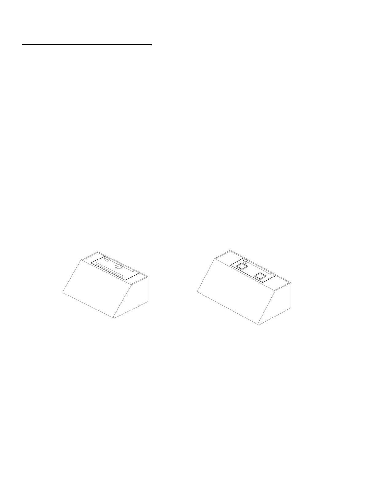
MODEL IDENTIFICATION:
PSVH24 PSVH30 PSVH36 PSVH48 PSVH60
PSVH36HL PSVH48HL PSVH60HL
When planning an installation within an enclosure outside the house, in addition to the standard installation
instructions the following construction and installation recommendations should be followed:
1. The location of the hood must be planned to prevent direct or indirect exposure to water spray
(with the exception of fire suppression devices)
2. All framing and soffit construction must be of non-combustible materials.
3. All wall surface construction materials and finishes must be of non-combustible materials.
4. All electrical connections must have ground fault interruption (GFI) protection.
5. External venting of the hood must be properly planned and capped to prevent the
entrance of water into the ducting system.
6. Fasteners approved for moist environments are recommended when mounting the hood.
INSTALATION IN ENCLOSED OUT DOOR ENVIRENMENT
12
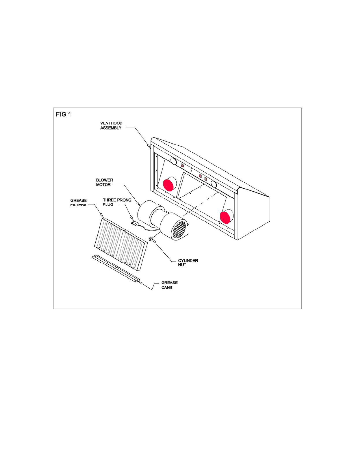
BLOWER MOTOR REMOVAL:
The Capital Performance Vent Hood has been designed to accommodate easy and safe installation. The following
procedure is best done with the hood on it’s back and on a padded surface. The Blower motor can be separated
from the hood assembly by first removing the grease filters and then the grease cans (fig 1). Locate the disconnect plug
and unplug. Next locate the cylinder nut directly below the blower motor and with large screwdriver remove the cylinder
nut. Once the cylinder nut has been removed, the blower motor can now be lifted up and out.
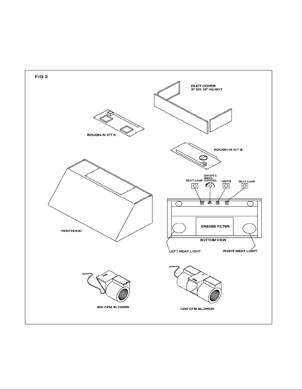
VENT HOOD ASSEMBLY
13
14
VENT HOOD INSTALLATION (WITH SOFFIT)
SITE PREPARTION:
This Capital Performance Vent Hood has been designed to accommodate installation into a
1. Soffit structure (ceiling mount), or, for sites without a soffit structure.
2. Directly into the wall through holes provided in the rear panel of the Vent Hood (wall mount). When mounting
the hood to a soffit, it is recommended to also utilize the rear panel holes to gain additional stability and
minimize any vibration noise. We suggest that the final framing and wall finishing be done with the vent hood at
the site to more accurately locate ductwork and electrical service.
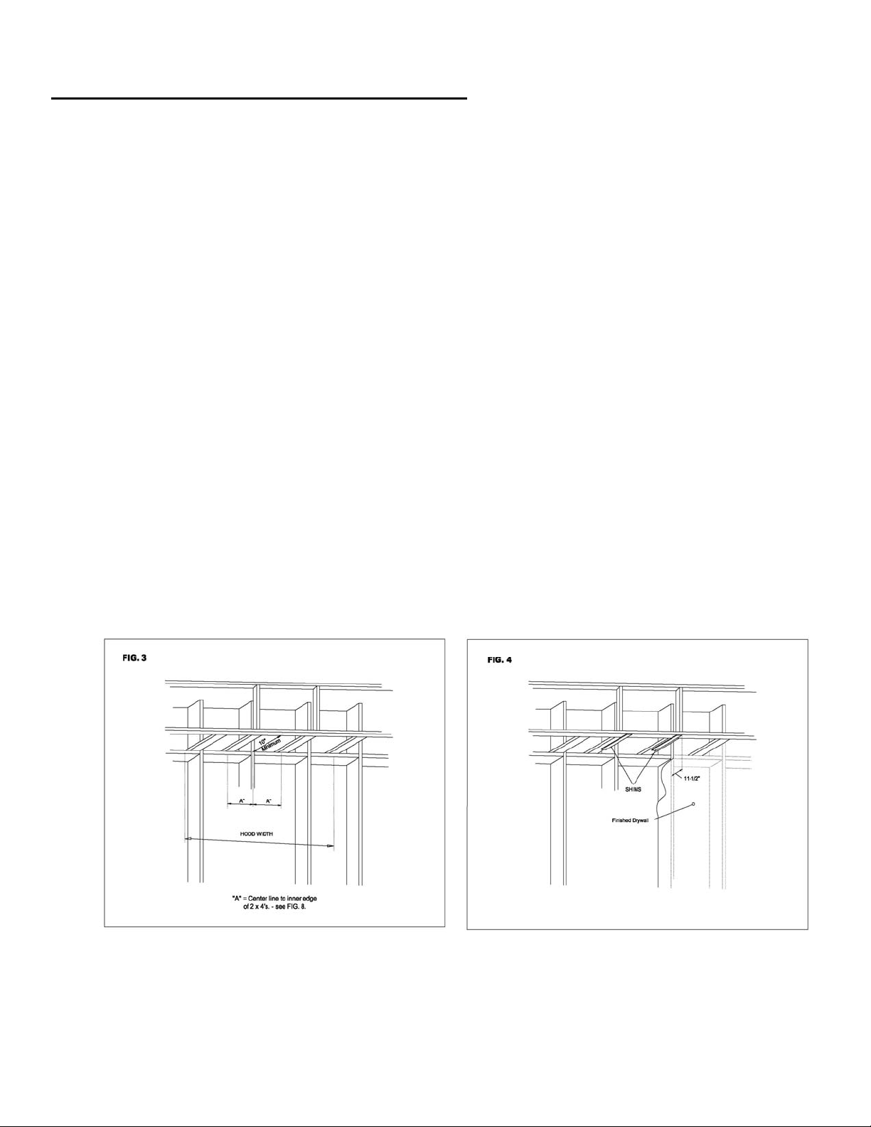
CONSTRUCT SOFFIT FRAMING:
1. For a site with a soffit, use 2” x 4”s to construct the soffit framing as showing below in fig. 1. Note that the
minimum opening of 10” is needed to accommodate the ductwork. With the centerline of the installation
marked, nail down the 2” x 4’s (wide side down) so that their inner edges are those specified from the
centerline. (see Figs. 3 & 4)
NOTE: The second (outer) set of 2” x 4”s are not necessary on the 30” model installation.
2. Make two wood shims (2 x 10⁻¹/2 “ x drywall thickness). Attach them to the framing as
shown in Fig. 4. Mount shims flush with edges of framing and with front edges 11-1/2”
from finished back wall.
15
VENT HOOD INSTALLATION (WITH SOFFIT)-CONT.
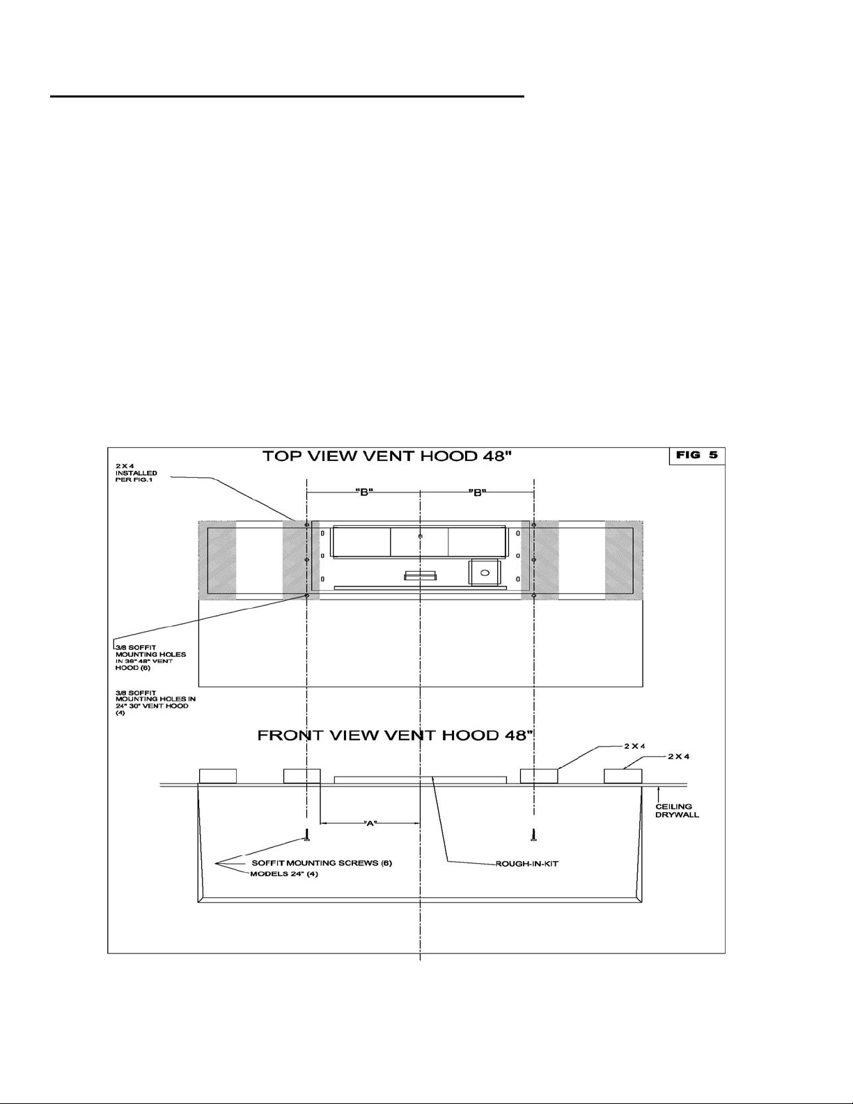
INSTALL VENT HOOD INTO SOFFIT:
At this point in the installation process, the blower motor should be removed from the hood assembly and set aside
(see-page 5). With the blower motor set aside, there is clear access to the soffit mounting holes and wall mounting
holes in the rear panel of the unit.
Once the soffit framing has been completed, place assembled Vent Hood (hood, rough-in kit, and ventilator) into place
and secure hood to the soffit frame with six wood screws.
NOTE: Additionally, we recommend the installer utilize the holes provided in the rear panel of the hood to secure the
hood to the rear wall and minimize any noise and vibration of unit.
NOTE: Assure that the mounting screws are long enough to be driven through the wood shims into the installed 2” x 4”s
for total support. (see fig. 5)
GO TO FINISHING THE INSTALLATION – Page 11
16
VENT HOOD INSTALLATION (WITHOUT SOFFIT)
SITE PREPARATION:
In cases where the installation site does not have a soffit structure, the Vent Hood assembly may be secured directly to
the wall from the rear of the unit.
NOTE: When installing the Vent Hood directly to the rear wall, an adequate structural wall support (studs) must exist to
secure the unit.
NOTE: The Capital Duct Cover should be ordered and installed when installing the Vent Hood in a site without a soffit.
Capital offers both a 6” and 12” height Cover. Keep the 6” or 12” dimension in mind when allowing for clearance
between the top of the Vent Hood and the ceiling. (see fig.8)
1. With the Vent Hood width, and installation site in mind, mark the centerline of the installation.
2. See the chart in fig. 8 to determine the centerline to centerline dimension of the wall mounting holes for the
particular model being installed.
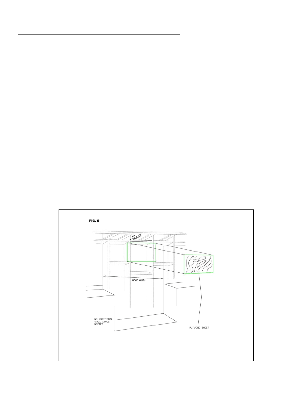
3. Cut away enough drywall (if installed) to expose 2 vertical studs (1 in each side of the hood centerline). It will be
necessary to construct a plywood wall insert (see fig. 6) or install aligning wall studs. (see fig. 7)
WALL MOUNTING
After an adequate wall structure has been completed, secure the Capital Duct Cover (6” or 12”) to the top of the Vent
Hood. Carefully lift the hood with the duct cover into the installation site and secure the hood into the wall structure with
six mounting screws. Once the hood assembly has been secured to the wall, the front of the soffit chimney may be
removed for ductwork connections.
GO TO FINISHING THE INSTALLATION – Page 11
`

17

18
FINISHING THE INSTALLATION
TO FINISH THE INSTALLATION:
Once the Ventilation Hood has bee mounted in
place it will be necessary to install the electrical
service. All electrical work should be done by a
qualified electrician and must conform to all local
standards. Refer to the wiring diagrams on Pages
17 & 18, for proper hook-up and grounding.
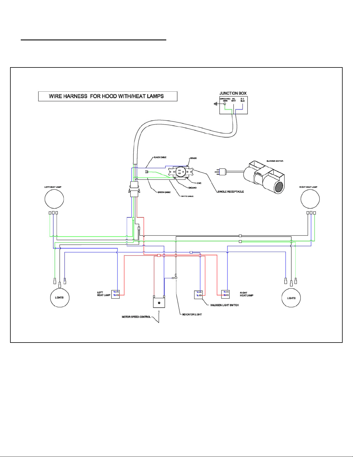
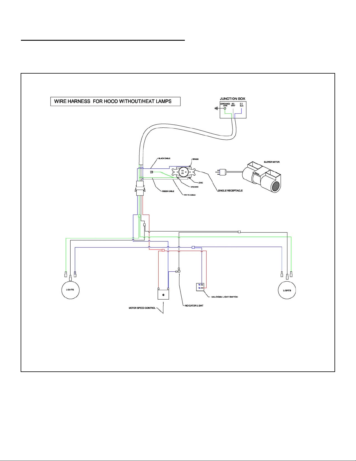
NOTE: Black = live, White = neutral, Green = ground
Complete installation by making ductwork connections,
testing unit functions, and installing & finishing drywall.
CARE AND USE:
CONTROLS – We recommend you turn your hood on before you begin cooking to establish fresh air flow. After you’ve
finished cooking, let the blower run for a few minutes to clear the air and help keep the kitchen fresh and clean.
BLOWER – The speed control knob turns the blower ON/OFF and adjusts blower speed. To adjust speed turn the
speed knob clockwise to decrease and counterclockwise to increase the blower speed.
HOOD LIGHTING – A single switch controls both lights. Use only 50W maximum Halogen Narrow Flood replacement
bulbs.
CAUTION: Halogen lamps are constructed of a glass bulb with a pressurized internal filament tube that operates at high
temperatures and could unexpectedly shatter. Should the outer bulb break, particles of extremely hot glass could be
discharged into the fixture enclosure and/or surrounding environment, thereby creating a risk of personal injury or fire.
When replacing the bulb, let the bulb cool, and assure that power to the light has been turned off. Never allow hot bulb
to come into contact with water.
Do not touch the hood light bulbs when in use. They may be hot enough to cause injury.
WARMING LAMPS – Each warming lamp is controlled by it’s own ON/OFF switch. Use only R40 size, 250W maximum
infrared bulbs.
FILTERS – Filters should be cleaned frequently in a detergent solution and are dishwasher safe. Empty grease
collection tray/s regularly. Remove filter/s by gently pulling up and out. Grease collection tray/s are beneath each filter/s.
UNPLUG THE BLOWER MOTOR BEFORE CLEANING VENTILATOR –
Remove filter to access blower motor plug. Vacuum blower to clean. Do not immerse in water.
Do not allow an excessive accumulation of grease, use a mild detergent when cleaning.
Do not use harsh abrasives, steel wool pads, or abrasive cloths.
19
DUCT INFORMATION
GENERAL:
When planning the path for ducting to outside, keep in
mind the following guidelines:
Minimize use of elbows and transitions in ductwork as
to maximize air flow to outside of building. An effective
airflow path contributes to the overall efficiency of the
Vent Hood.
Capital recommends the use of smooth wall ducting, not
flexible ductwork.
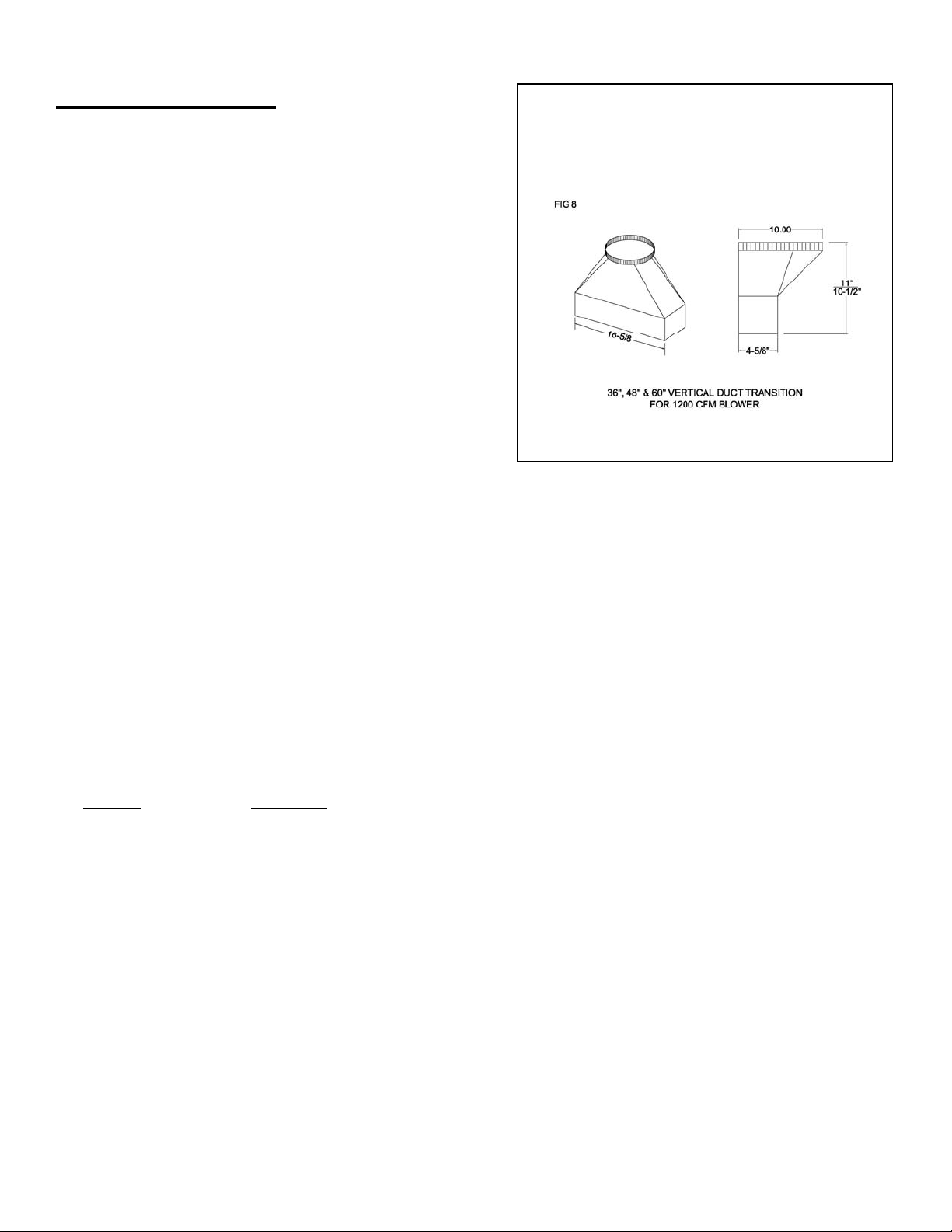
Transitions are required from rectangular to round ducting.
Capital’s PSVH Blower requires one of the following 4-1/2” x 18” to 10” round transitions
(purchased separately)
Model PSVH - Vertical
Model PSVH - Rear discharge
Model PSVH - Left discharge
Duct tape may be used at ducting joints.
CAPITAL VH-36/48/60 Capital 12-36 REQUIREMENTS:
Capital recommends the use of 10” round ducting which provides 78.6 sq. in. of surface area.
Alternate duct sizes in rectangular style may be used. If rectangular duct style is used, the duct
must equal at least 78.6 sq. in. for best results. (Example 3-1/4” x 24” duct =78 sq. in.)
Maintain consistent ducting square area as to avoid reduced air flow. (Example with a VH-48 Hood, connecting a 4” x
13” 52 sq. in
. to a 10” round 78.6 sq. in. is not recommended)
CAPITAL VH-24/30 REQUIRMENTS:
Capital recommends the use of 7” round ducting which provides 34.7 sq. in. of surface area.
Alternate duct sizes in rectangular style may be used. If rectangular duct style is used, the duct must equal at least 34.7
sq. in. for best results.
DUCT ACCESSORIES:
Wall Caps and Roof Caps must have free open area equal to duct size diameter.
Note that a Sealed Back Draft Damper may reduce air delivery.

20
CAPITAL PSVH SERIES SPECIFICATIONS

21
SERVICE INFORMATION
Before you call for service, please have the following information available:
• Model Number
• Serial Number
• Date of Installation
• Copy of Receipt or Invoice
• A brief description of the problem
Your satisfaction is our top priority. If the problem persists, or is not resolved to your satisfaction by our service
consultant, please writ to us or fax us a letter at:
Capital Cooking Equipment, Inc.
Attn: Customer Service Manager
13211 East Florence Avenue
Santa Fe Springs, CA 90670
USA
Toll Free: 866-402-4600
Fax #: 562-903-1167
E-mail: customerservice@capital-cooking.com

22
WARRANTY
• One (1) year full parts and labor covers the entire unit.
• five (5) Years Limited Warranty Covers all Stainless steel parts
WILL PAY FOR:
All repair labor and parts found to be defective due to material or workmanship for one (1) full year “IN HOME” warranty.
This does not apply if the unit was subjected to other than normal household use. An Authorized Factory Agent must
provide Service during normal working hours. No charges will be made for repair or replacement at the location of
original installation or factory for parts returned pre-paid, through the dealer and claimed within the warranty period, and
found to be defective by Capital. All claims, regardless of warranty or non-warranty must be documented with photos
and detailed description and/or narrative of the problem.
Replacement will be F.O.B our factory. The company will not be liable for transportation costs, labor cost or export
duties. This warranty shall not apply, nor can we assume responsibility for damage that might result from failure to
follow manufacturer’s instructions or local codes where the appliance has been tempered with or altered in any way or
which, in our judgment, has been subjected to misuse, negligence, or accident. Implied warranty shall not extend
beyond the duration of this written warranty. This warranty is in lieu of all warranties, expressed or implied and all other
obligations or liability in connection with the sale of this product.
WILL NOT PAY FOR:
• Installation or start-up.
• Shipping damage.
• Service by an unauthorized agency.
• Use of unauthorized parts.
• Service during hours other than normal working hours.
• Improper installation.
• Service visit to teach you how to operate the appliance, correct the installation, reset circuit breakers or replace
fuses.
• Repair other than normal household use.
• Damage caused by accident, abuse, alteration, misuse, incorrect installation or installation not in accordance
with local codes.
• Unit installed in non-residential application.
This warranty applies to appliances used in residential application only. It does not cover their use in
commercial situations (commercial situations include but are not limited to restaurants, public parks and
recreation areas, any area where units are exposed to multiple users, public cooking areas, etc.) This
warranty is for products purchased and retained in the 50 States of the U.S.A, the District of Columbia
and Canada. This warranty applies even if you should move during the warranty period. Should the
original purchaser sell the appliance during the warranty period, the new owner continues to be
protected until the expiration date of the original purchaser’s warranty period. This warranty gives you
the specific legal rights. You may also have other rights, which vary from State to State.
23
WIRING DIAGRAM WITH HEAT LAMP:
24
WIRING DIAGRAM WITHOUT HEAT LAMP:

25
NOTES___________________________________________________________

26
NOTES___________________________________________________________

22
THESE SPECIFICATIONS ARE FOR PLANNING PURPOSES ONLY.
CONSULT WITH AN AUTHORIZED TECHNICIAN FOR YOUR SPECIFIC VENTILATION.
REQUIREMENTS. FOR THE MOST UP TO DATE INFORMATION, CONTACT CAPITAL
COOKING EQUIPMENT, INC. INDICATING THE MODEL # .
WE RESERVE THE RIGHT TO CHANGE THESE SPECIFICATIONS OR DESIGN WITHOUT NOTICE.
THE POWER OF PERFORMANCE
13211 E. FLORENCE AVE. SANTA FE SPRINGS, CA 90670.
PHONE 866-402-4600
WWW.CAPITAL-COOKING.COM
PART NO 87023-02 rev-1