
Please read this manual carefully before operating
your set.
Retain it for future reference.
Record model number and serial number of the set.
See the label attached on the back cover and quote
this information to your dealer
when you require service.
Note: All features shown within this guide may not be available
on all models.
LCD TV
OWNER’S MANUAL
Hospital Grade Models
22LG3DCH 26LG3DCH 32LG3DCH
Lodging Gr
ade Model
32LG3DC
Inst
aller Reference for C
ommercial Mode
Commercial Mode Setup see pages 91-110
Channel Banks Setup see pages 87-90
Pillow Speaker Setup see page 29
MPI/PPV Card Setup see page 20
P/NO : SAC30708037 (0810-REV00)
www.lgcommercial.com


1
WARNING / CAUTION
WARNING / CAUTION
To prevent fire or shock hazards, do not expose
this product to rain or moisture.
FCC NOTICE
Class B digital device
This equipment has been tested and found to comply
with the limits for a Class B digital device, pursuant to
Part 15 of the FCC Rules. These limits are designed
to provide reasonable protection against harmful
interference in a residential installation. This equipment
generates, uses and can radiate radio frequency energy
and, if not installed and used in accordance with the
instructions, may cause harmful interference to radio
communications. However, there is no guarantee that
interference will not occur in a particular installation.
If this equipment does cause harmful interference to
radio or television reception, which can be determined
by turning the equipment off and on, the user is
encouraged to try to correct the interference by one
or more of the following measures:
- Reorient or relocate the receiving antenna.
- Increase the separation between the equipment and
receiver.
- Connect the equipment to an outlet on a circuit
different from that to which the receiver is connected.
- Consult the dealer or an experienced radio/TV
technician for help.
Any changes or modifications not expressly approved
by the party responsible for compliance could void
the user’s authority to operate the equipment.
CAUTION
Do not attempt to modify this product in any way
without written authorization from LG Electronics.
Unauthorized modification could void the user’s
authority to operate this product
The lightning flash with arrowhead
symbol, within an equilateral triangle, is
intended to alert the user to the presence
of uninsulated “dangerous voltage” within the
product’s enclosure that may be of sufficient
magnitude to constitute a risk of electric shock to
persons.
The exclamation point within an equilateral
triangle is intended to alert the user to
the presence of important operating and
maintenance (servicing) instructions in the litera-
ture accompanying the appliance.
TO REDUCE THE RISK OF ELECTRIC SHOCK
DO NOT REMOVE COVER (OR BACK). NO
USER SERVICEABLE PARTS INSIDE. REFER TO
QUALIFIED SERVICE PERSONNEL.
WARNING/CAUTION
TO REDUCE THE RISK OF FIRE AND ELECTRIC
SHOCK, DO NOT EXPOSE THIS PRODUCT TO
RAIN OR MOISTURE.
NOTE TO CABLE/TV INSTALLER
This reminder is provided to call the CATV system
installer’s attention to Article 820-40 of the National
Electric Code (U.S.A.). The code provides guidelines for
proper grounding and, in particular, specifies that the
cable ground shall be connected to the grounding system
of the building, as close to the point of the cable entry
as practical.
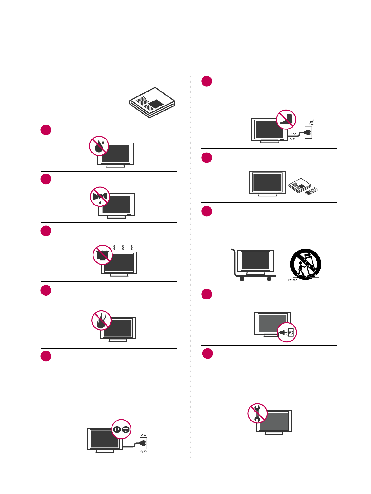
Read these instructions.
Keep these instructions.
Heed all warnings.
Follow all instructions.
Do not use this apparatus near water.
Clean only with dry cloth.
Do not block any ventilation openings. Install in
accordance with the manufacturer’s instructions.
Do not install near any heat sources such as
radiators, heat registers, stoves, or other apparatus
(including amplifiers)that produce heat.
Do not defeat the safety purpose of the polarized
or grounding-type plug. A polarized plug has
two blades with one wider than the other. A
grounding type plug has two blades and a third
grounding prong, The wide blade or the third
prong are provided for your safety. If the provided
plug does not fit into your outlet, consult an
electrician for replacement of the obsolete outlet.
Protect the power cord from being walked on
or pinched particularly at plugs, convenience
receptacles, and the point where they exit from
the apparatus.
Only use attachments/accessories specified by
the manufacturer.
Use only with the cart, stand, tripod, bracket,
or table specified by the manufacturer, or sold
with the apparatus. When a cart is used, use
caution when moving the cart/apparatus
combination to avoid injury from tip-over.
Unplug this apparatus during lighting storms or
when unused for long periods of time.
Refer all servicing to qualified service personnel.
Servicing is required when the apparatus has been
damaged in any way, such as power-supply cord or
plug is damaged, liquid has been spilled or objects
have fallen into the apparatus, the apparatus has
been exposed to rain or moisture, does not operate
normally, or has been dropped.
2
IMPORTANT SAFETY INSTRUCTIONS
SAFETY INSTRUCTIONS
1
2
3
4
5
7
8
6
9
10

3
Never touch this apparatus or antenna during a
thunder or lighting storm.
When mounting a TV on the wall, make sure not to
install the TV by the hanging power and signal
cables on the back of the TV.
Do not allow an impact shock or any objects to fall
into the product, and do not drop onto the screen
with something.
CAUTION concerning the Power Cord :
It is recommend that appliances be placed upon a
dedicated circuit; that is, a single outlet circuit which
powers only that appliance and has no additional
outlets or branch circuits. Check the specification
page of this owner's manual to be certain.
Do not connect too many appliances to the same
AC power outlet as this could result in fire or elec-
tric shock.
Do not overload wall outlets. Overloaded wall out-
lets, loose or damaged wall outlets, extension cords,
frayed power cords, or damaged or cracked wire
insulation are dangerous. Any of these conditions
could result in electric shock or fire. Periodically
examine the cord of your appliance, and if its
appearance indicates damage or deterioration,
unplug it, discontinue use of the appliance, and
have the cord replaced with an exact replacement
part by an authorized servicer. Protect the power
cord from physical or mechanical abuse, such as
being twisted, kinked, pinched, closed in a door, or
walked upon. Pay particular attention to plugs, wall
outlets, and the point where the cord exits the
appliance.
Do not make the TV with the power cord plugged
in. Do not use a damaged or loose power cord. Be
sure do grasp the plug when unplugging the power
cord. Do not pull on the power cord to unplug the
TV.
WARNING - To reduce the risk of fire or electrical
shock, do not expose this product to rain, moisture
or other liquids. Do not touch the TV with wet
hands. Do not install this product near flammable
objects such as gasoline or candles or expose the
TV to direct air conditioning.
Do not expose to dripping or splashing and do not
place objects filled with liquids, such as vases, cups,
etc. on or over the apparatus (e.g. on shelves above
the unit).
GGRROOUUNNDDIINNGG
Ensure that you connect the earth ground wire to
prevent possible electric shock. (i.e. a TV with a
three-prong grounded AC plug must be connected
to a three-prong grouned AC outlet) If grounding
methods are not possible, have a qualified electri-
cian install a separate circuit breaker.
Do not try to ground the unit by connecting it to
telephone wires, lightening rods, or gas pipes.
DDIISSCCOONNNNEECCTTIINNGG DDEEVVIICCEE FFRROOMM MMAAIINNSS
Mains plug is the disconnecting device. The plug
must remain readily operable.
Keep the product away from direct sunlight.
12
11
14
13
16
17
18
19
Power
Supply
Short-circuit
Breaker
15
4
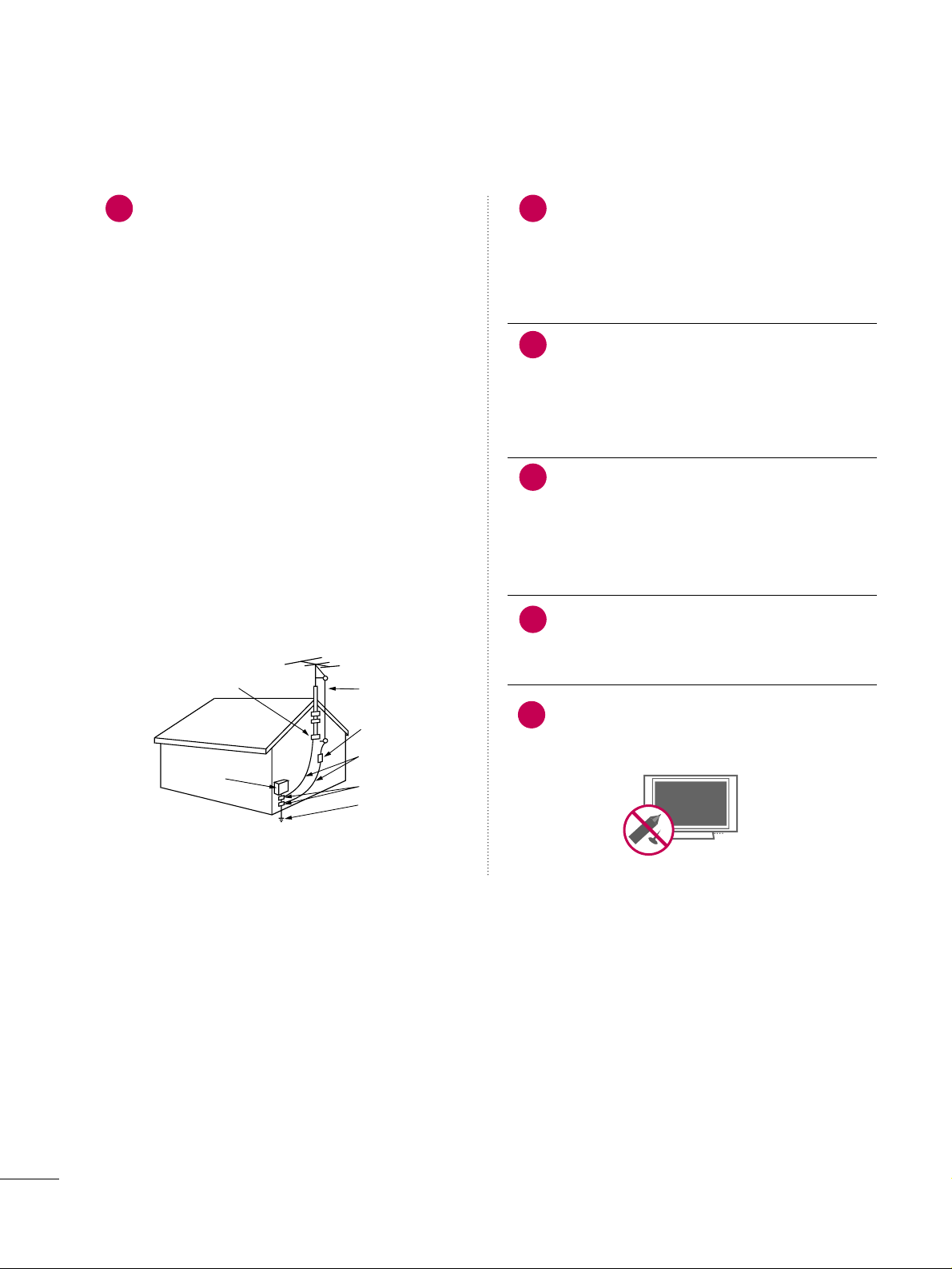
AANNTTEENNNNAASS
OOuuttddoooorr aanntteennnnaa ggrroouunnddiinngg
If an outdoor antenna is installed, follow the precau-
tions below. An outdoor antenna system should not
be located in the vicinity of overhead power lines or
other electric light or power circuits, or where it can
come in contact with such power lines or circuits as
death or serious injury can occur.
Be sure the antenna system is grounded so as to pro-
vide some protection against voltage surges and
built-up static charges.
Section 810 of the National Electrical Code (NEC) in
the U.S.A. provides information with respect to prop-
er grounding of the mast and supporting structure,
grounding of the lead-in wire to an antenna dis-
charge unit, size of grounding conductors, location of
antenna discharge unit, connection to grounding
electrodes and requirements for the grounding elec-
trode.
AAnntteennnnaa ggrroouunnddiinngg aaccccoorrddiinngg ttoo tthhee
NNaattiioonnaall EElleeccttrriiccaall CCooddee,, AANNSSII//NNFFPPAA 7700
Cleaning
When cleaning, unplug the power cord and scrub
gently with a soft cloth to prevent scratching. Do not
spray water or other liquids directly on the TV as
electric shock may occur. Do not clean with chemi-
cals such as alcohol, thinners or benzene.
Moving
Make sure the product is turned off, unplugged
and all cables have been removed. It may take 2 or
more people to carry larger TVs. Do not press
against or put stress on the front panel of the TV.
Ventilation
Install your TV where there is proper ventilation. Do
not install in a confined space such as a bookcase.
Do not cover the product with cloth or other mate-
rials (e.g.) plastic while plugged in. Do not install in
excessively dusty places.
If you smell smoke or other odors coming from the
TV or hear strange sounds, unplug the power cord
contact an authorized service center.
Do not press strongly upon the panel with a hand or
sharp object such as nail, pencil or pen, or make a
scratch on it.
22
20
Antenna Lead in Wire
Antenna Discharge Unit
(NEC Section 810-20)
Grounding Conductors
(NEC Section 810-21)
Ground Clamps
Power Service Grounding
Electrode System (NEC
Art 250, Part H)
Ground Clamp
Electric Service
Equipment
NEC: National Electrical Code
23
24
21
25

5
CONTENTS
WARNING / CAUTION
. . . . . . . . . . . . . . . . . . . . . . . . . . . . 1
SAFETY INSTRUCTIONS
. . . . . . . . . . . . . . . . . . . . . . . . . .
2
FEATURES OF THIS TV
. . . . . . . . . . . . . . . . . . . . . . . . . . . . . 7
PREPARATION
Accessories
. . . . . . . . . . . . . . . . . . . . . . . . . . . . . . . . . . . . . . . . . . . . . . . . . . . . . . 8
Front Panel Information
. . . . . . . . . . . . . . . . . . . . . . . . . . . . . . . . . . . . . 9
Back Panel Information
. . . . . . . . . . . . . . . . . . . . . . . . . . . . . . . . . . . . 10
Stand Instruction
. . . . . . . . . . . . . . . . . . . . . . . . . . . . . . . . . . . . . . . . . . . . . 12
Cable Management
. . . . . . . . . . . . . . . . . . . . . . . . . . . . . . . . . . . . . . . . . 13
Desktop Pedestal Installation
. . . . . . . . . . . . . . . . . . . . . . . . . . . . 14
Swivel Stand
. . . . . . . . . . . . . . . . . . . . . . . . . . . . . . . . . . . . . . . . . . . . . . . . . . . . 14
Attaching the TV to a desk
. . . . . . . . . . . . . . . . . . . . . . . . . . . . . . . 15
VESA Wall Mounting
. . . . . . . . . . . . . . . . . . . . . . . . . . . . . . . . . . . . . . . . 16
VESA Standard TV Mounts
. . . . . . . . . . . . . . . . . . . . . . . . . . . . . . . 17
Securing the TV to the wall to prevent falling
When the TV is used on a stand
. . . . . . . . . . . . . . . . . . . . . . . . . . 18
Antenna or Cable Connection
. . . . . . . . . . . . . . . . . . . . . . . . . . 19
MPI Card Slot
. . . . . . . . . . . . . . . . . . . . . . . . . . . . . . . . . . . . . . . . . . . . . . . . . 20
EXTERNAL EQUIPMENT SETUP
HD Receiver Setup
. . . . . . . . . . . . . . . . . . . . . . . . . . . . . . . . . . . . . . . . . 21
DVD Setup
. . . . . . . . . . . . . . . . . . . . . . . . . . . . . . . . . . . . . . . . . . . . . . . . . . . . . 24
VCR Setup
. . . . . . . . . . . . . . . . . . . . . . . . . . . . . . . . . . . . . . . . . . . . . . . . . . . . . 26
Other A/V Source Setup
. . . . . . . . . . . . . . . . . . . . . . . . . . . . . . . . .
28
Pillow Speaker Setup
. . . . . . . . . . . . . . . . . . . . . . . . . . . . . . . . . . . . . . . 29
PC Setup
. . . . . . . . . . . . . . . . . . . . . . . . . . . . . . . . . . . . . . . . . . . . . . . . . . . . . . . . 30
WATCHING TV / CHANNEL CONTROL
Remote Control Functions
. . . . . . . . . . . . . . . . . . . . . . . . . . . . . . . 36
Installer Remote Control Functions
. . . . . . . . . . . . . . . . . . . 38
Turning On TV
. . . . . . . . . . . . . . . . . . . . . . . . . . . . . . . . . . . . . . . . . . . . . . . . 40
Channel Selection
. . . . . . . . . . . . . . . . . . . . . . . . . . . . . . . . . . . . . . . . . . . 41
Volume Adjustment
. . . . . . . . . . . . . . . . . . . . . . . . . . . . . . . . . . . . . . . . . 41
On-Screen Menus Selection
. . . . . . . . . . . . . . . . . . . . . . . . . . . . . 42
Channel Setup
- Auto Scan (Auto Tuning)
. . . . . . . . . . . . . . . . . . . . . . . . . . . 43
- Add / Delete Channel (Manual Tuning)
. . . . . . 44
- Channel Editing
. . . . . . . . . . . . . . . . . . . . . . . . . . . . . . . . . . . . . . . . 45
Channel Label
. . . . . . . . . . . . . . . . . . . . . . . . . . . . . . . . . . . . . . . . . . . . . . . . . 46
Input List
. . . . . . . . . . . . . . . . . . . . . . . . . . . . . . . . . . . . . . . . . . . . . . . . . . . . . . . . 47
PICTURE CONTROL
Picture Size (Aspect Ratio) Control . . . . . . . . . . . . . . . . . . 48
Preset Picture Settings
- Picture Mode - Preset
. . . . . . . . . . . . . . . . . . . . . . . . . . . . . . . 51
- Color Tone - Preset
. . . . . . . . . . . . . . . . . . . . . . . . . . . . . . . . . . . 52
Manual Picture Adjustment
- Picture Mode - User Mode
. . . . . . . . . . . . . . . . . . . . . . . .
53
- Picture Mode - Expert Control
. . . . . . . . . . . . . . . . . . 54
Picture Improvement Settings
. . . . . . . . . . . . . . . . . . . . . . . . . . . 55
Advanced Control - Black (Darkness) Level
. . . . . . .
56
Advanced Control - Real Cinema
. . . . . . . . . . . . . . . . . . . . . .57
Picture Reset
. . . . . . . . . . . . . . . . . . . . . . . . . . . . . . . . . . . . . . . . . . . . . . . . . 58
SOUND & LANGUAGE CONTROL
Auto Volume Leveler (Auto Volume)
. . . . . . . . . . . . . . . . . 59
Clear Voice
. . . . . . . . . . . . . . . . . . . . . . . . . . . . . . . . . . . . . . . . . . . . . . . . . . . . . 60
Preset Sound Settings (Sound Mode)
. . . . . . . . . . . . . . . 61
Sound Setting Adjustment - User Mode
. . . . . . . . . . . 62
- SRS TruSurround XT
. . . . . . . . . . . . . . . . . . . . . . . . . . . . . . . . . 63
Balance
. . . . . . . . . . . . . . . . . . . . . . . . . . . . . . . . . . . . . . . . . . . . . . . . . . . . . . . . . . 64
TV Speakers On/Off Setup
. . . . . . . . . . . . . . . . . . . . . . . . . . . . . . 65
Audio Reset
. . . . . . . . . . . . . . . . . . . . . . . . . . . . . . . . . . . . . . . . . . . . . . . . . . . 66
Stereo/SAP Broadcast Setup
. . . . . . . . . . . . . . . . . . . . . . . . . . . 67
Audio Language
. . . . . . . . . . . . . . . . . . . . . . . . . . . . . . . . . . . . . . . . . . . . . . 68
On-Screen Menus Language Selection
. . . . . . . . . . . . . 69
Caption Mode
- Analog Broadcasting System Captions
. . . . . . . 70
- Digital Broadcasting System Captions
. . . . . . . . 71
- Caption Option
. . . . . . . . . . . . . . . . . . . . . . . . . . . . . . . . . . . . . . . 72
TIME SETTING
Clock Setting
- Auto Clock Setup
. . . . . . . . . . . . . . . . . . . . . . . . . . . . . . . . . . . . 73
- Manual Clock Setup
. . . . . . . . . . . . . . . . . . . . . . . . . . . . . . . . . 74
Auto On/Off Time Setting
. . . . . . . . . . . . . . . . . . . . . . . . . . . . . . 75
Sleep Timer Setting
. . . . . . . . . . . . . . . . . . . . . . . . . . . . . . . . . . . . . . . . . 76
Auto Shut-off Setting
. . . . . . . . . . . . . . . . . . . . . . . . . . . . . . . . . . . . . . . 77

6
PARENTAL CONTROL / RATINGS
Set Password & Lock System . . . . . . . . . . . . . . . . . . . . . . . . . . . 78
Channel Blocking
. . . . . . . . . . . . . . . . . . . . . . . . . . . . . . . . . . . . . . . . . . . . 81
Movie & TV Rating
. . . . . . . . . . . . . . . . . . . . . . . . . . . . . . . . . . . . . . . . . 82
Downloadable Rating
. . . . . . . . . . . . . . . . . . . . . . . . . . . . . . . . . . . . . . 85
External Input Blocking
. . . . . . . . . . . . . . . . . . . . . . . . . . . . . . . . . . . . 86
CHANNEL BANKS
Channel Banks Overview . . . . . . . . . . . . . . . . . . . . . . . . . . . . . . . . . . 87
Channel Banks Setup Installer Remote Control Key
Functions
. . . . . . . . . . . . . . . . . . . . . . . . . . . . . . . . . . . . . . . . . . . . . . . . . . . . . . . .88
Channel Banks Setup
. . . . . . . . . . . . . . . . . . . . . . . . . . . . . . . . . . . . . . 89
Reference: Channel Banks Worksheet
. . . . . . . . . . . . . . . 90
COMMERCIAL MODE SETUP
Installer Overview
. . . . . . . . . . . . . . . . . . . . . . . . . . . . . . . . . . . . . . . . . . . . 91
TV overview
. . . . . . . . . . . . . . . . . . . . . . . . . . . . . . . . . . . . . . . . . . . . . . . . . . . .
92
Commercial Mode Setup for Master TV
. . . . . . . . . . . . 93
Master TV Profile Setup Learning/Teaching with
USB Memory Card
. . . . . . . . . . . . . . . . . . . . . . . . . . . . . . . . . . . . . . . . . . 94
TLL-1100A Clone Connections / Learning and
Teaching Setups
. . . . . . . . . . . . . . . . . . . . . . . . . . . . . . . . . . . . . . . . . . . . . .96
LT2002 Cloning Connections/Learning Setup
. . 97
Cloning Learning Setup
. . . . . . . . . . . . . . . . . . . . . . . . . . . . . . . . . . . 98
Cloning Connections/Teaching Setup
. . . . . . . . . . . . .99
Installer Menu
. . . . . . . . . . . . . . . . . . . . . . . . . . . . . . . . . . . . . . . . . . . . . . . .10 0
Reference: Detailed Information For Making A
Master TV
. . . . . . . . . . . . . . . . . . . . . . . . . . . . . . . . . . . . . . . . . . . . . . . . . . . . .10 7
Reference: Procedures for adding Channel Label
Icons/Custom Channel Labels (2-5-4 + MENU
Mode)
. . . . . . . . . . . . . . . . . . . . . . . . . . . . . . . . . . . . . . . . . . . . . . . . . . . . . . . . . . .10 8
Reference: Clonable Menu Features
. . . . . . . . . . . . . . . . .109
Reference: Checking Software Version
. . . . . . . . . . . . .10 9
TV Aux Input Configuration
. . . . . . . . . . . . . . . . . . . . . . . . . . . . .110
Power Saving Setup
. . . . . . . . . . . . . . . . . . . . . . . . . . . . . . . . . . . . . . . . .110
APPENDIX
Troubleshooting . . . . . . . . . . . . . . . . . . . . . . . . . . . . . . . . . . . . . . . . . . . . . .111
Reference: LT2002 Cloning Procedure
Troubleshooting
. . . . . . . . . . . . . . . . . . . . . . . . . . . . . . . . . . . . . . . . . . . . . .113
Channel Banks Setup Troubleshooting
. . . . . . . . . . . . .114
Troubleshooting Flow Chart
. . . . . . . . . . . . . . . . . . . . . . . . . . . .115
Commercial Mode Check
. . . . . . . . . . . . . . . . . . . . . . . . . . . . . . . .116
Glossary of Terms
. . . . . . . . . . . . . . . . . . . . . . . . . . . . . . . . . . . . . . . . . . .
117
Maintenance
. . . . . . . . . . . . . . . . . . . . . . . . . . . . . . . . . . . . . . . . . . . . . . . . . . .118
Product Specifications
. . . . . . . . . . . . . . . . . . . . . . . . . . . . . . . . . . . .119
IR Codes
. . . . . . . . . . . . . . . . . . . . . . . . . . . . . . . . . . . . . . . . . . . . . . . . . . . . . . .
120
7
is a trademark of SRS Labs, Inc.
TruSurround XT technology is incorporated under
license from SRS Labs, Inc.
Manufactured under license from Dolby Laboratories.
“
Dolby
“and the double-D symbol are trademarks of
Dolby Laboratories.
FEATURES OF THIS TV
USB IN
SERVUCE ONLYSERVUCE ONLY
USB port shall be used for software update by service
personnel only.
FOR LCD TV
■
If the TV feels cold to the touch, there may be a small “flicker” when it is turned on. This is normal, there is nothing wrong
with TV.
■
Some minute dot defects may be visible on the screen, appearing as tiny red, green, or blue spots. However, they have no adverse
effect on the monitor's performance.
■
Avoid touching the LCD screen or holding your finger(s) against it for long periods of time. Doing so may produce some
temporary distortion effects on the screen.
On Disposal
The fluorescent lamp used in this product contains a small amount of mercury. Do not dispose of this product with general
household waste. Disposal of this product must be carried out in accordance to the regulations of your local authority.
HDMI
TM
, the HDMI logo and High-Definition
Multimedia Interface are trademarks or registered
trademarks of HDMI Licensing."
PREPARATION
8
PREPARATION
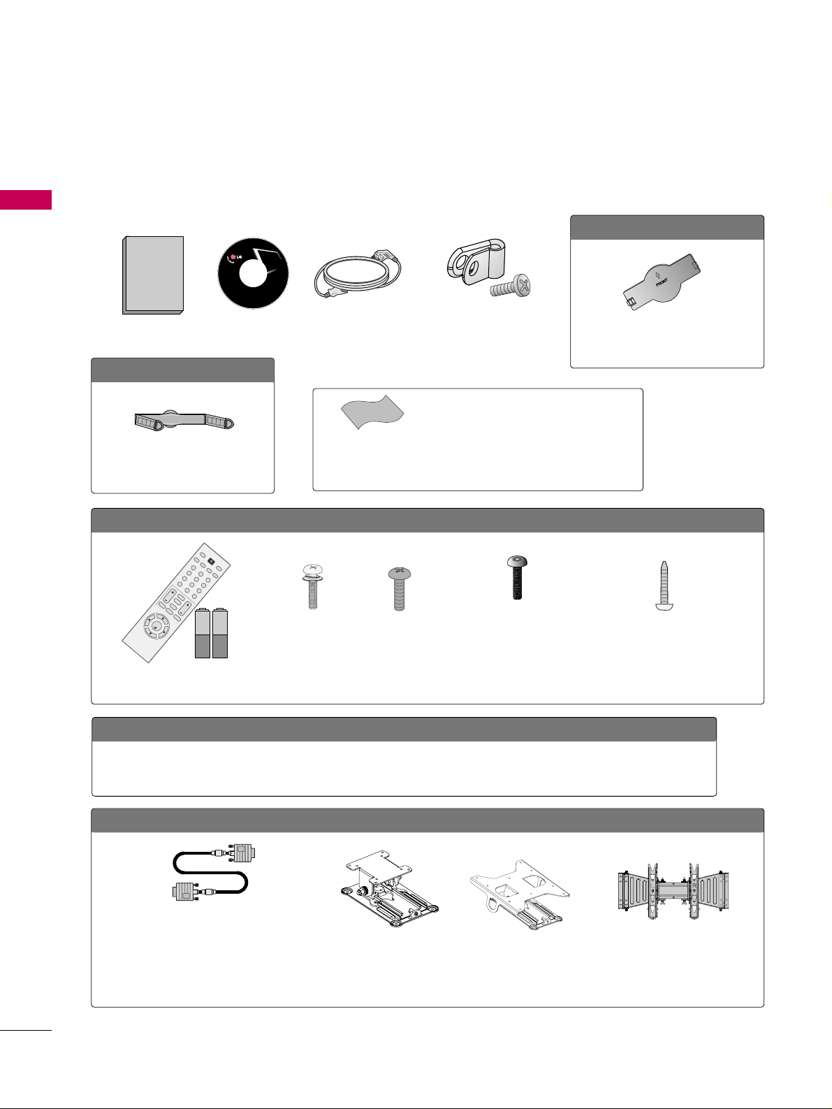
ACCESSORIES
Ensure that the following accessories are included with your TV. If an accessory is missing, please contact the
dealer where you purchased the TV.
The accessories included may differ from the images below.
OOppttiioonn EExxttrraass
D-sub 15 pin Cable
When using the VGA (D-sub 15 pin cable) PC
connection, the user must use shielded signal
interface cables with ferrite cores to maintain
standards compliance.
OOppttiioonnaall IInnssttaalllleerr RReemmoottee CCoonnttrrooll ffoorr MMooddeell NNoo.. SSeerriieess 2222//2266//3322LLGG33DDCCHH
There is an optional Installer remote control available for the 22/26/32LG3DCH models. The
installer remote control is NOT included with the TV.
Tilt Wall Mounting Bracket
(AW-47LG30M)
(Only 32LG3DCH)
Wall Mounting Bracket
(RW230)
(Only 26LG3DCH)
3322LLGG33DDCC oonnllyy
1.5V 1.5V
Remote Control,
Batteries
123
456
78
0-
9
VOL CH
ENTER
POWER
MUTE
MENU
A
D
JU
S
T
R
ETU
R
N
CC
SAP
FLASHBK
PICTURE
S
O
U
N
D
RATIO
TV
IN
P
U
T
TIMER
Bolts for stand assembly
(Refer to P.12)
Screw for stand fixing
(Refer to P.15)
x 4 x 4
x 2
Torx plus
Star head screw
(Refer to P.12)
M4xL26
(Machine Screw)
Ø
4xL20
(Plastic Screw)
Ø
4xL20
(Plastic Screw)
M4xL22
(Machine Screw)
Wall Mounting Bracket
(RW120)
(Only 22LG3DCH)
2222LLGG33DDCCHH oonnllyy
Copyright© 2007 LGE,
All Rights Reserved.
Owner’s Manual
Power Cord
CD Manual
Cable Management Clip
(Refer to P.13)
2266//3322LLGG33DDCCHH,, 3322LLGG33DDCC oonnllyy
Protection Cover
(Refer to P.12)
Protective Bracket and
Bolt for Power Cord
(Refer to P.13)
(This feature is not available for
all models.)
* Wipe spots on the exterior only with the pol-
ishing cloth.
* Do not wipe roughly when removing stains.
Excessive pressure may cause scratches or
discoloration.
Polishing Cloth
(This feature is not avail-
able for all models.)
PREPARATION
9
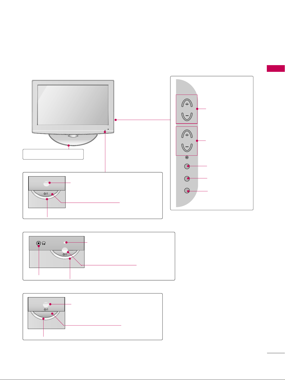
FRONT PANEL INFORMATION
■
Image shown may differ from your TV.
■
NOTE: If your TV has a protection tape attached, remove the tape.
And then wipe the TV with a cloth (If a polishing cloth is included with your TV, use it).
POWER Button
Power/Standby Indicator
Illuminates red in standby mode.
Illuminates blue when the set is switched on.
CH
VOL
MENU
INPUT
ENTER
VOLUME (+, -)
Buttons
ENTER Button
MENU Button
INPUT Button
Remote Control Sensor
CHANNEL(+, -)
Buttons
POWER Button
Power/Standby Indicator
Illuminates red in standby mode.
Illuminates green when the set is switched
on.
Remote Control Sensor
Stand
26/32LG3DCH model
32LG3DC model
(only 32LG3DC)
22LG3DCH model
POWER Button
Power/Standby Indicator
Illuminates red in standby mode.
Illuminates green when the set is
switched on.
Remote Control Sensor
Headphone

PREPARATION
10
PREPARATION
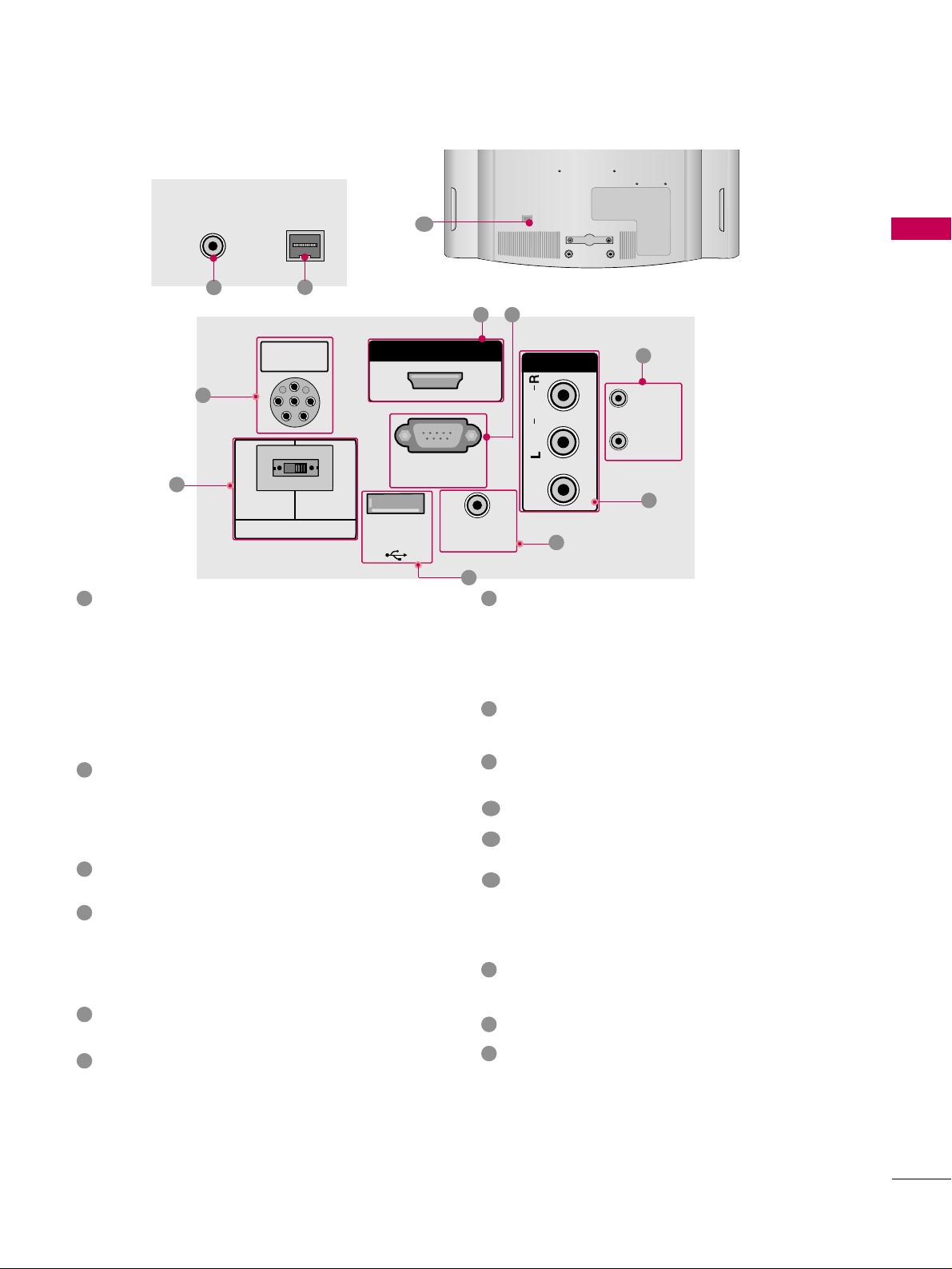
BACK PANEL INFORMATION
■
Image shown may differ from your TV.
R
( )
1
11
AUDIO IN
(RGB/DVI)
VIDEO
AUDIO
HDMI/DVI IN
USB IN
SERVUCE ONLY
AV IN 1
VIDEO
MONO
( )
AUDIO
S-VIDEO
COMPONENT
IN
RGB IN (PC)
RESET
UPDATE
RS-232C IN
(SERVICE ONLY)
REMOTE
CONTROL OUT
SPEAKER OUT
8
AV IN 2
L/MONO
R
AUDIO
VIDEO
H/P
PILLOW
SPEAKER
NORMAL
SPEAKER
PILLOW
SPEAKER
SPEAKER SWITCH
PILLOW
SPEAKER
NORMAL
SPEAKER
PILLOW
SPEAKER
SPEAKER SWITCH
12
AUDIO IN
(RGB/DVI)
VIDEO
AUDIOAUDIO
HDMI/DVI INHDMI/DVI IN
USB INUSB IN
SERVUCE ONLYSERVUCE ONLY
AV IN 1
VIDEOVIDEO
MONO
( )
AUDIOAUDIO
S-VIDEO
COMPONENTCOMPONENT
IN
RGB IN (PC)
RESET
UPDATE
RS-232C INRS-232C IN
(SERVICE ONLY)(SERVICE ONLY)
REMOTE
CONTROL OUT
SPEAKER OUT
8
R
PILLOW
SPEAKER
NORMALNORMAL
SPEAKERSPEAKER
PILLOWPILLOW
SPEAKERSPEAKER
SPEAKER SWITCH
PILLOW
SPEAKER
NORMAL
SPEAKER
PILLOW
SPEAKER
SPEAKER SWITCH
6
5
1
8
2
3
4
9 10
15
(only 26/32LG3DCH model)
For 32LG3DC
26/32LG3DCH
R
( )
ANTENNA INANTENNA IN
M.P.I.M.P.I.
7
13
14
PREPARATION
11
For 22LG3DCH
R
( )
ANTENNA INANTENNA IN
M.P.I.M.P.I.
13
14
12
R
PILLOW
SPEAKER
NORMAL
SPEAKER
PILLOW
SPEAKER
SPEAKER SWITCH
PILLOWPILLOW
SPEAKERSPEAKER
HDMI/DVI INHDMI/DVI IN
RS-232C INRS-232C IN
(SERVICE ONLY)(SERVICE ONLY)
USB INUSB IN
SERVUCE ONLYSERVUCE ONLY
REMOTEREMOTE
CONTROL OUTCONTROL OUT
AV IN AV IN
VIDEOVIDEO
AUDIOAUDIO
MONOMONO
( )
NORMALNORMAL
SPEAKERSPEAKER
PILLOWPILLOW
SPEAKERSPEAKER
SPEAKER SWITCHSPEAKER SWITCH
RESETRESET
UPDATEUPDATE
PILLOW
SPEAKER
RS-232C IN
(SERVICE ONLY)
USB IN
SERVUCE ONLY
REMOTE
CONTROL OUT
AV IN
VIDEO
AUDIO
MONO
( )
NORMAL
SPEAKER
PILLOW
SPEAKER
SPEAKER SWITCH
RESET
UPDATE
DVI AUDIO IN
DVI AUDIO INDVI AUDIO IN
15
15
2
5
1
3
4
9
COMPONENT IN (Except 22LG3DCH model)
Analog Connection.
Supports HD.
Uses a red, green, and blue cable for video & a red
and white cable for audio.
AUDIO IN (RGB/DVI)
(Except 22LG3DCH model)
1/8” headphone jack for analog PC audio input.
REMOTE CONTROL OUT
IR output for controlling an auxiliary device.
SPEAKER OUT 8
Ω (Except 22LG3DCH model)
H/P
Plug the headphone into the headphone socket.
Power Cord Socket
For operation with AC power.
Caution: Never attempt to operate the TV on DC
power.
ANTENNA IN
Connect over-the air signals to this jack.
M.P. I.
PILLOW SPEAKER (Except 32LG3DC model)
Used to connect to pillow speaker.
SPEAKER SWITCH (Except 32LG3DC model)
Used to select the speaker output switch.
Note: If Pillow Speaker is selected, no Sound will be
heard from TV speakers.
(NORMAL SPEAKER or PILLOW SPEAKER)
AV (Audio/Video) IN
Analog composite connection. Supports standard
definition video only (480i).
Used for PC/DTV audio input jack (Only 22LG3DCH-
UA model).
S-VIDEO (Except 22LG3DCH model)
Better quality than standard composite (yellow
RCA cable). Supports standard definition video
only (480i).
HDMI/DVI IN
Digital Connection. Supports HD video and Digital
audio.
Accepts DVI video using an adapter or HDMI to
DVI cable (not included).
USB IN SERVICE ONLY
Used for software updates.
UPDATE
Software downloads and debug mode enable/dis-
able.
RESET
Hardware reset to PTC microcontroller.
RS-232C IN (SERVICE ONLY)
Used for software updates.
RGB IN (PC) (Except 22LG3DCH model)
Analog PC Connection. Uses a D-sub 15 pin cable
(VGA cable).
1
2
3
4
5
9
8
6
10
11
12
13
14
15
7

PREPARATION
12
PREPARATION
STAND INSTRUCTION
Carefully place the TV screen side down on a
cushioned surface to protect the screen from
damage.
Assemble the parts of the
SSTTAANNDD BBOODDYY
with
CCOOVVEERR BBAASSEE
of the TV.
1
2
Insert the stand as shown.
3
SSTTAANNDD BBOODDYY
CCOOVVEERR BBAASSEE
■
Image shown may differ from your TV.
GG
Make sure the screws in the stand are fully
tightened. (If not tightened fully, the product
could tilt forward and fall). But do not over
tighten, over-tightening can damage the threads
on the screws.
NOTE
!
DETACHMENT
(Only 32LG3DC)
Carefully place the TV screen side down on a
cushioned surface to protect the screen from
damage.
1
Remove the four screws that hold the base on.
2
Detach the stand from TV.
3
After removing the stand, install the included
pprrootteeccttiioonn ccoovveerr
over the hole for the stand.
Press the
PPRROOTTEECCTTIIOONN CCOOVVEERR
into the TV
until you hear it click.
PROTECTION COVER
(Except 22LG3DCH)
INSTALLATION
(Only 32LG3DC)
4
or
x 4
Tighten the stand with the
four screws (provided as parts
of the TV).
Tighten the two of these four screws
and the two Torx plus star head screws
(provided as parts of the TV) to secure the TV. Tighten
the two Torx plus star head screws with a star head dri-
ver bit (not provided as parts of the TV).
x 2
x 2
PREPARATION
13
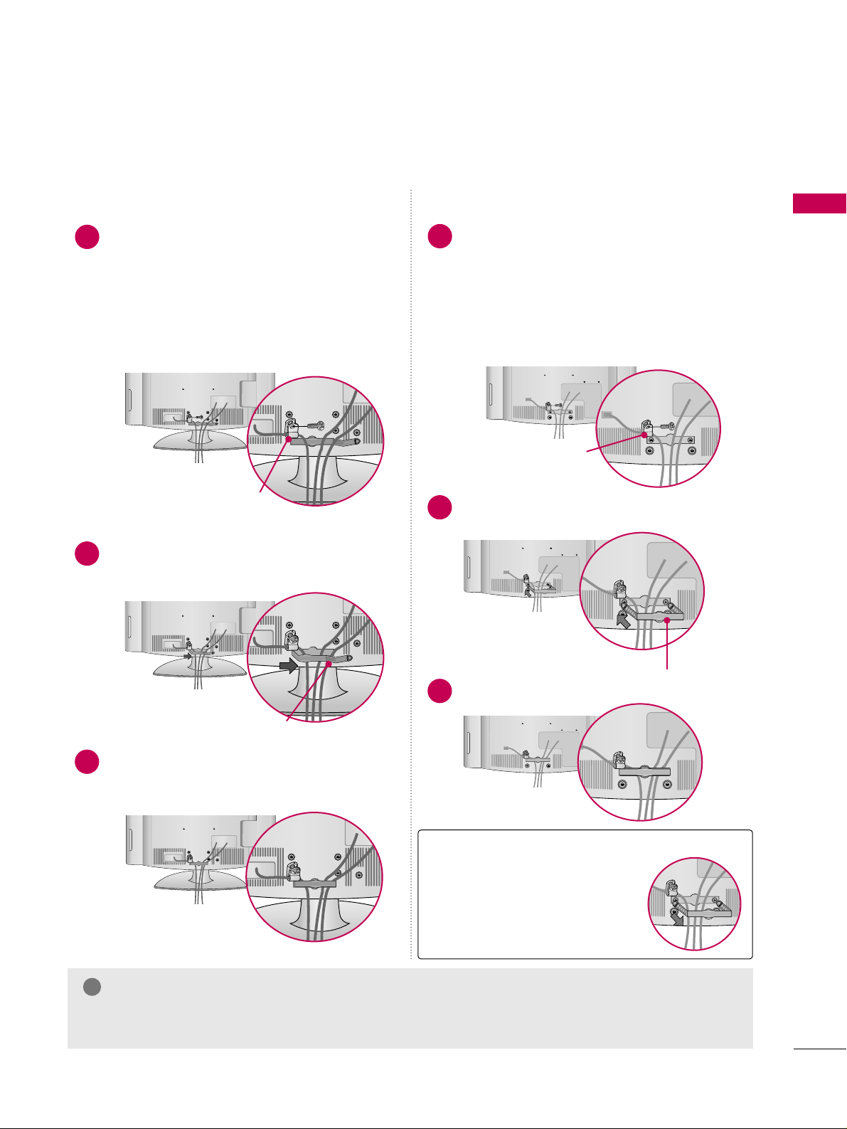
CABLE MANAGEMENT
Install the CABLE MANAGEMENT CLIP as
shown.
2
■
Image shown may differ from your TV.
Connect the cables as necessary.
To connect additional equipment, see the
EXTERNAL EQUIPMENT SETUP section.
Secure the power cable with the
PROTECTIVE BRACKET and the screw as
shown. It will help prevent the power cable
from being removed by accident.
Install the CABLE MANAGEMENT CLIP as
shown.
CABLE MANAGEMENT CLIP
1
2
Put the cables inside the CABLE MANAGEMENT
CLIP and snap it closed.
3
PROTECTIVE BRACKET
(This feature is not available
for all models.)
Connect the cables as necessary.
To connect additional equipment, see the
EXTERNAL EQUIPMENT SETUP section.
Secure the power cable with the
PROTECTIVE BRACKET and the screw as
shown. It will help prevent the power cable
from being removed by accident.
CABLE MANAGEMENT CLIP
1
Fit the CABLE MANAGEMENT CLIP as shown.
3
GG
Do not hold the CABLE MANAGEMENT CLIP when moving the TV.
- If the TV is dropped, you may be injured or the product may be broken.
NOTE
!
How to remove the
CABLE MANAGEMENT CLIP
GG
Hold the CABLE MANAGE-
MENT CLIP with both hands
and pull it backward.
For 22LG3DCH For 26/32LG3DCH, 32LG3DC
PROTECTIVE BRACKET
(This feature is not available
for all models.)
PREPARATION
14
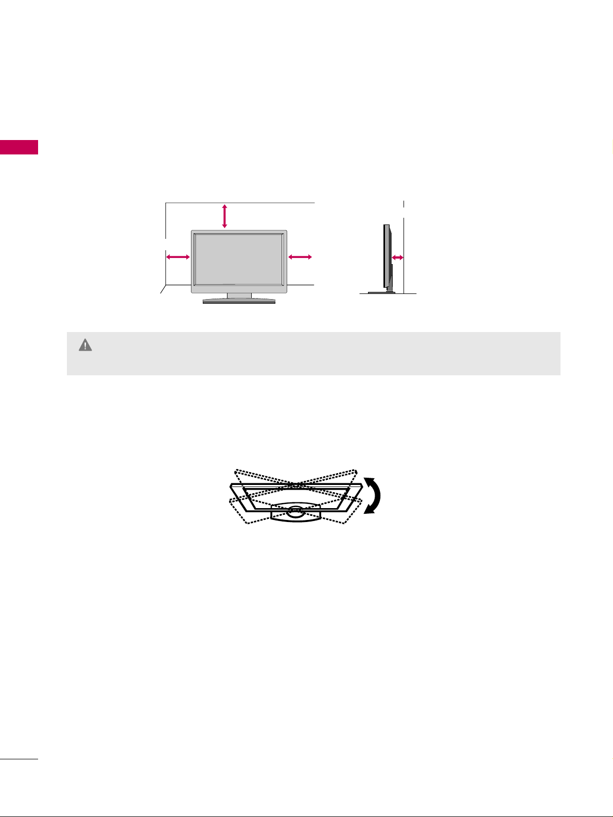
PREPARATION
DESKTOP PEDESTAL INSTALLATION
For proper ventilation, allow a clearance of 4 inches on all four sides.
■
Image shown may differ from your TV.
* This feature is not available for all models.
4 inches
4 inches
4 inches
4 inches
SWIVEL STAND (Only 32LG3DC)
The TV can be conveniently swivelled on its stand 90° to the left or right to provide the optimum viewing angle.
GG
Ensure adequate ventilation by following the clearance recommendations.
GG
Do not mount near or above any type of heat source.
CAUTION
PREPARATION
15
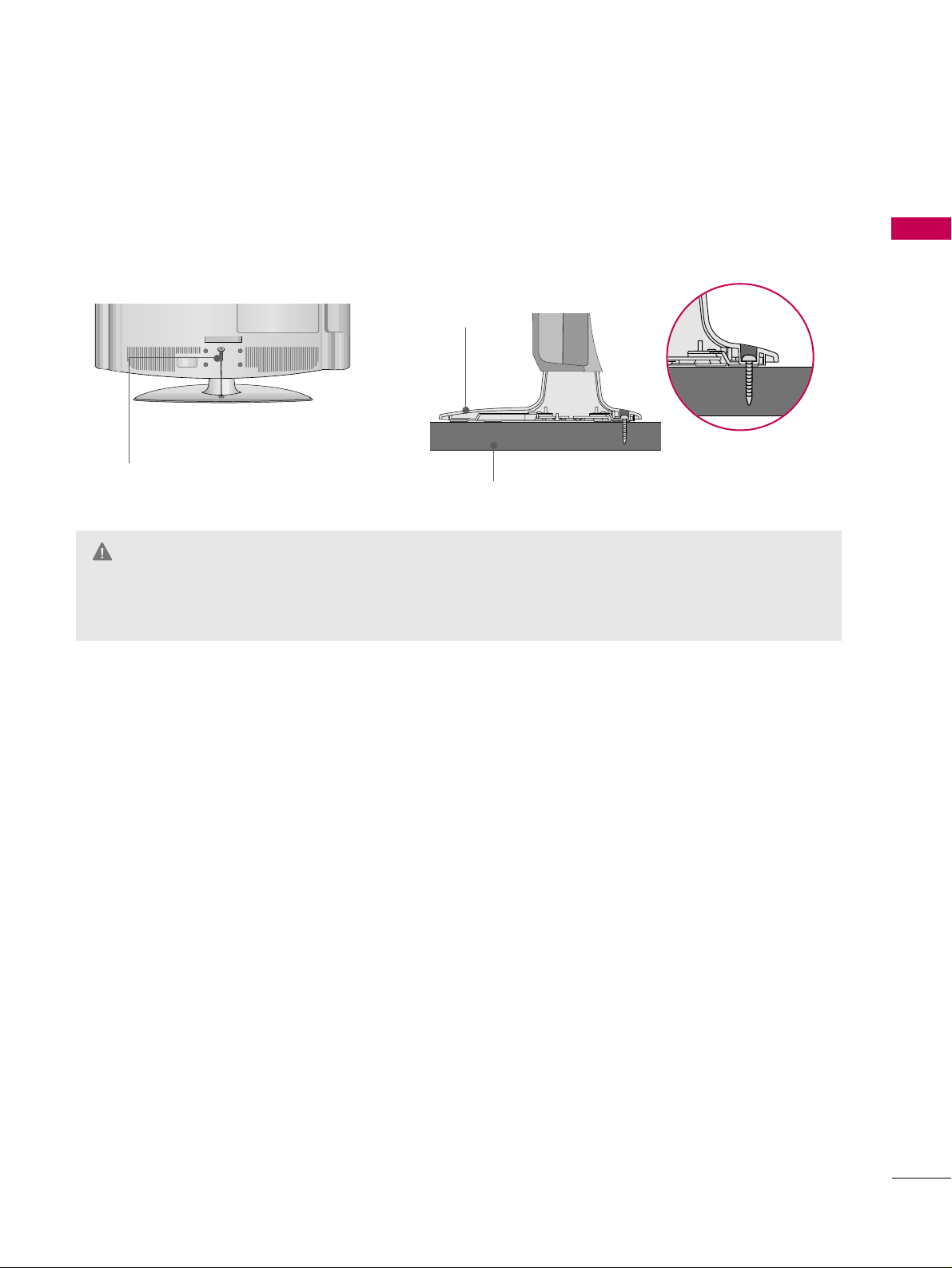
ATTACHING THE TV TO A DESK (Only 32LG3DC)
The TV must be attached to a desk so it cannot be pulled in a forward/backward direction, potentially causing
injury or damaging the product. Use only the included screw.
GG
To prevent TV from falling over, the TV should be securely attached to the floor/wall per installation
instructions. Tipping, shaking, or rocking the TV may cause injury.
WARNING
1-Screw
(provided as parts of the product)
Desk
Stand
PREPARATION
16
PREPARATION
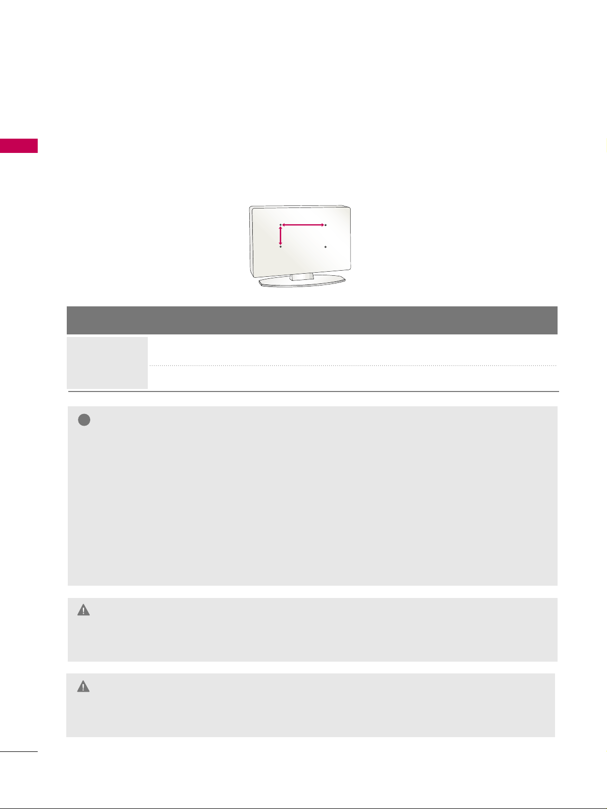
VESA WALL MOUNTING
Install your wall mount on a solid wall perpendicular to the floor. When attaching to other building materi-
als, please contact your nearest dealer.
If installed on a ceiling or slanted wall, it may fall and result in severe personal injury.
We recommend that you use an LG brand wall mount when mounting the TV to a wall.
GG
Do not install your wall mount kit while the TV is plugged in. It may result in personal injury due to electric
shock.
CAUTION
GG
Screw length needed depends on the wall mount
used. For further information, refer to the instruc-
tions included with the mount.
GG
Standard dimensions for wall mount kits are shown
in the table.
GG
When purchasing our wall mount kit, a detailed
installation manual and all parts necessary for
assembly are provided.
GG
Do not use screws longer then the standard dimen-
sion, as they may cause damage to the inside to
the TV.
GG
For wall mounts that do not comply with the VESA
standard screw specifications, the length of the
screws may differ depending on their specifica-
tions.
GG
Do not use screws that do not comply with the
VESA standard screw specifications.
Do not tighten the screws too much. It may dam-
age the TV or allow the TV to a fall and cause per-
sonal injury. LG is not liable for these kinds of acci-
dents.
GG
LG is not liable for TV damage or personal injury
when a non-VESA or non specified wall mount is
used or the consumer fails to follow the TV installa-
tion instructions.
NOTE
!
Product Model
VESA
(A
*
B)
Standard Screw Quantity
26LG3DCH, 32LG3DCH
32LG3DC
200
*
10 0
M4 4
LCD TV
AA
BB
GG
To prevent injury, this apparatus must be securely attached to the wall in accordance with the installa-
tion instructions.
WARNING
22LG3DCH 100
*
10 0
M4
4

PREPARATION
17
General Guidelines: Choosing a
Location for installing a VESA
Standard
MMoouunntt
To the right are some examples of VESA standard
mounts. Since there are numerous types of stands and
mounts available, only a few are shown here. Refer to the
instructions provided with the TV stand that will be
used to mount the TV. Be sure the style of stand select-
ed is capable of supporting the weight of the TV and is
appropriate for the application.
WWaallll MMoouunnttss
If the mount will be on a wall, a typical wooden stud
behind the wall board would be the preferred choice for
a location to attach the wall mount. The wall mount
location chosen should be appropriate for drilling holes
and have available the required power source as well as
antenna/cable and any other equipment leads as neces-
sary.
PPeeddeessttaall MMoouunnttss aanndd SSttaannddss
A sturdy surface on a desk or other similar flat table-like
furniture would be the appropriate location for mount-
ing a pedestal-style TV stand.
Most stands are designed so that the wiring is threaded
through the stand itself or a loop-through style clamp
so that the wiring is neatly bunched and not strung in
such a way as to create a potential hazard to the user.
(Some stands are portable and can be moved from one
location to another.) Be sure all safety considerations
are followed.
Typical Pedestal Type Mount with
Swivel Bracket
Typical Wall Stud Type Mount with Swivel
Bracket
VESA STANDARD TV MOUNTS
PREPARATION
18
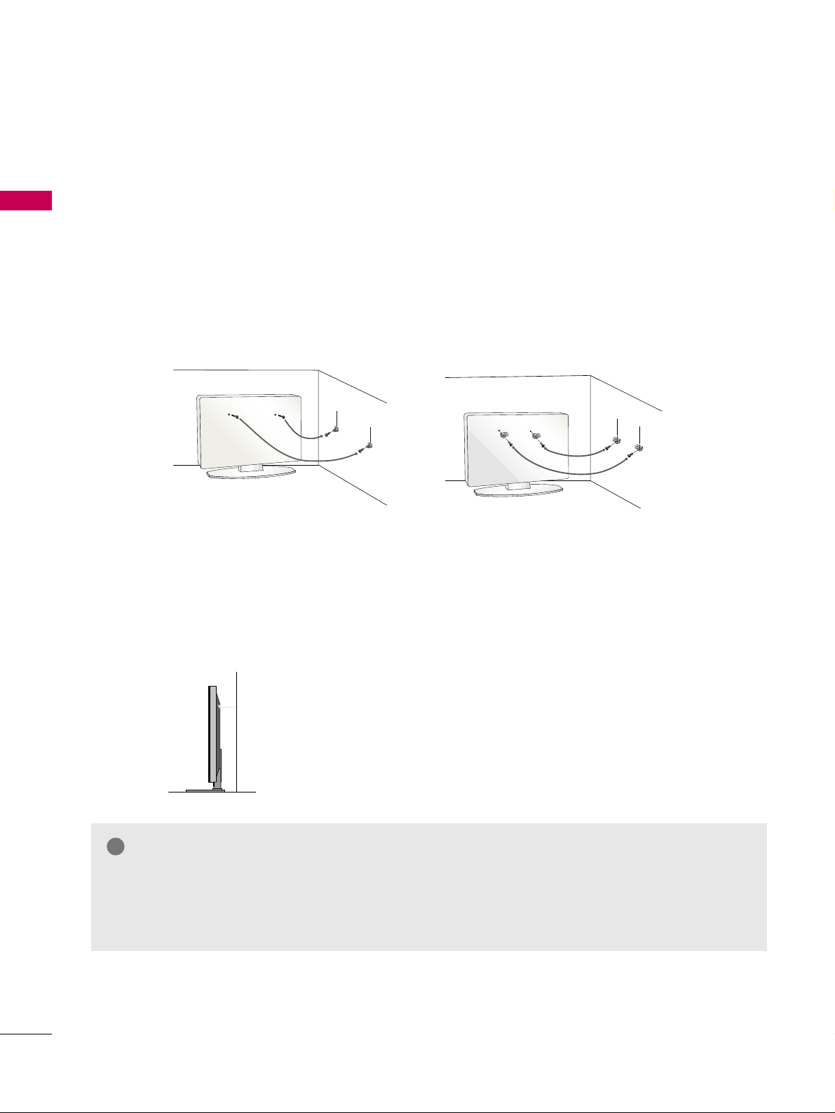
SECURING THE TV TO THE WALL TO PREVENT FALLING
WHEN THE TV IS USED ON A STAND
PREPARATION
We recommend that you set the TV close to a wall so it cannot fall over if pushed backwards.
Additionally, we recommend that the TV be attached to a wall so it cannot be pulled in a forward direction,
potentially causing injury or damaging the product.
Caution: Please make sure that children don’t climb on or hang from the TV.
■
Insert eye-bolts (or TV brackets and bolts) to attach the product to the wall as shown in the picture.
*If your product has the bolts in the eye-bolts position before inserting the eye-bolts, loosen the bolts.
* Insert the eye-bolts or TV brackets/bolts and tighten them securely in the upper holes.
Secure the wall brackets with screws (sold separately) to the wall. Match the height of the bracket that
is mounted on the wall to the holes in the product.
Ensure the eye-bolts or brackets are tightened securely.
■
Use a sturdy rope or cord (sold separately) to tie the product. It is
safer to tie the rope so it becomes horizontal between the wall and
the product (the less slack in the rope, the better).
■
You should purchase necessary components to prevent TV from falling off of the stand.
■
Image shown may differ from your TV.
* This feature is not available for all models.
GG
Use a platform or cabinet strong enough and large enough to support the size and weight of the TV.
GG
To use the TV safely, make sure that the height of the bracket on the wall and the one on the TV are
the same.
NOTE
!
PREPARATION
19
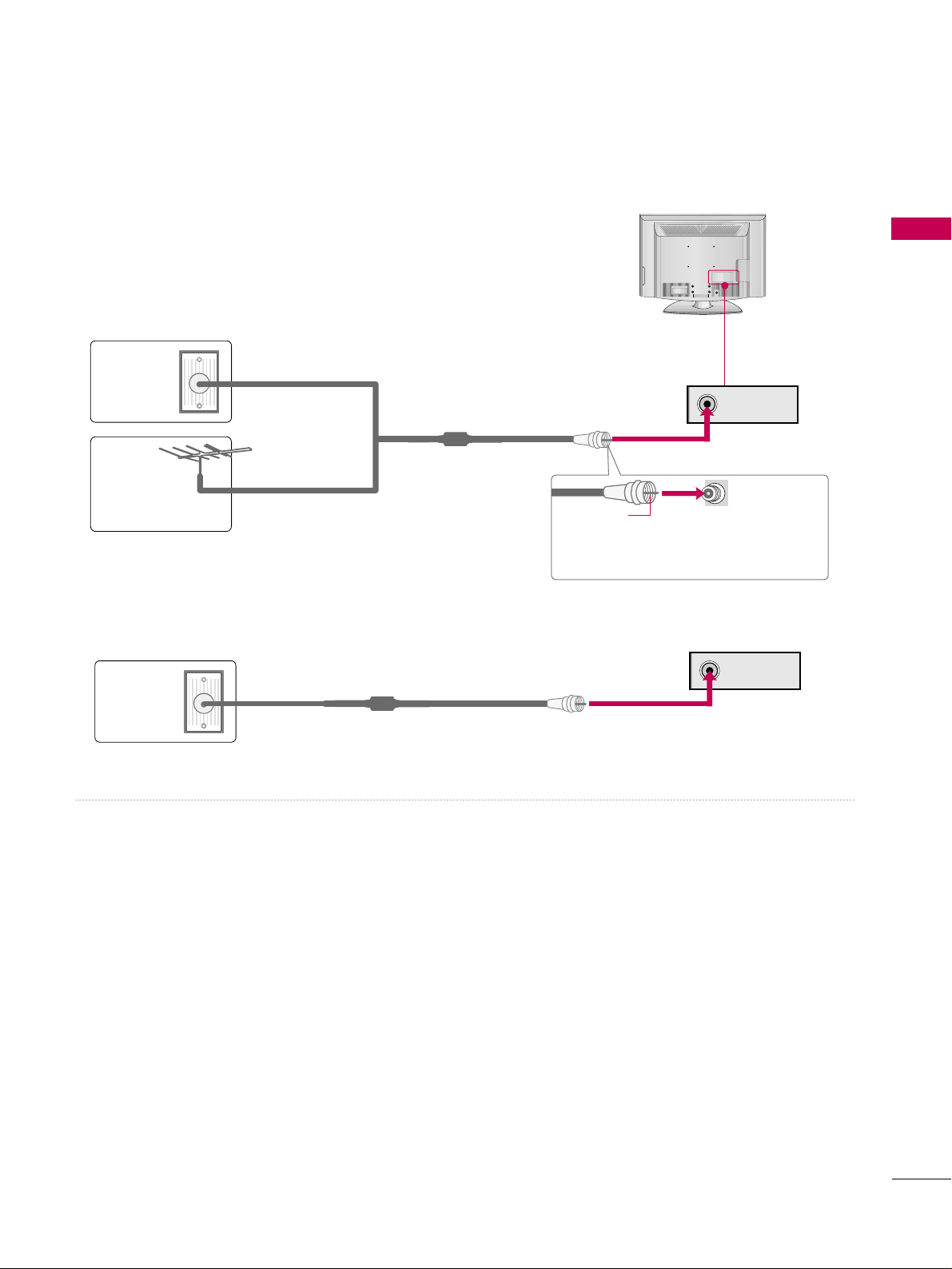
ANTENNA OR CABLE CONNECTION
■
To prevent damage do not connect to the power outlet until all connections are made between the devices.
ANTENNA IN
ANTENNA IN
1. Antenna (Analog or Digital)
Wall Antenna Socket or Outdoor Antenna without a Cable Box
Connection.
For optimum picture quality, adjust the direction if needed.
2. Cable
Wall
Antenna
Socket
Outdoor
Antenna
(VHF, UHF)
Cable TV
Wall Jack
Multi-family Dwellings/Apartments
(Connect to wall antenna socket)
RF Coaxial Wire (75 ohm)
RF Coaxial Wire (75 ohm)
Single-family Dwellings /Houses
(Connect to wall jack for outdoor antenna)
Be careful not to bend the copper wire
when connecting the antenna.
Copper Wire
■
To improve the picture quality in a poor signal area, please purchase a signal amplifier and install properly.
■
If the antenna needs to be split for two TV’s, install a 2-Way Signal Splitter.
■
If the antenna is not installed properly, contact your dealer for assistance.
R
( )

PREPARATION
20
PREPARATION
ANTENNAANTENNA IN
M.PM.P.I.
M.P. I.
Card Slot
RR FF CC AA BB LL EE
RF cable needs to be dis-
connected to remove cur-
rent card.
1. Remove the two MPI card retainer screws.
2. Pull out current MPI card far enough so that the RF cable can be detached from the old card.
2. Detach RF cable.
3. Place new PPV card into slot and slide it in far enough to reconnect RF cable.
4. Reconnect RF cable.
5. Insert card all the way into the slot making sure it is fully seated into back plane connector.
6. Replace the two card retainer screws.
The MPI card is equipped with an RF jack for antenna/cable signal source connection.
The slot is also available for installing a PPV (Pay-Per-View) card.
MPI Card Removal / PPV Card Installation
MPI CARD SLOT

EXTERNAL EQUIPMENT SETUP
21
EXTERNAL EQUIPMENT SETUP
■
To prevent the equipment damage, never plug in any power cords until you have finished connecting all equipment.
■
This part of EXTERNAL EQUIPMENT SETUP mainly uses the picture for 32LG3DC model.
HD RECEIVER SETUP
This TV can receive Digital Over-the-air or Digital Cable signals without an external digital set-top box. However,
if you do receive digital signals from a digital set-top box or other digital external device, refer to the figure as
shown below.
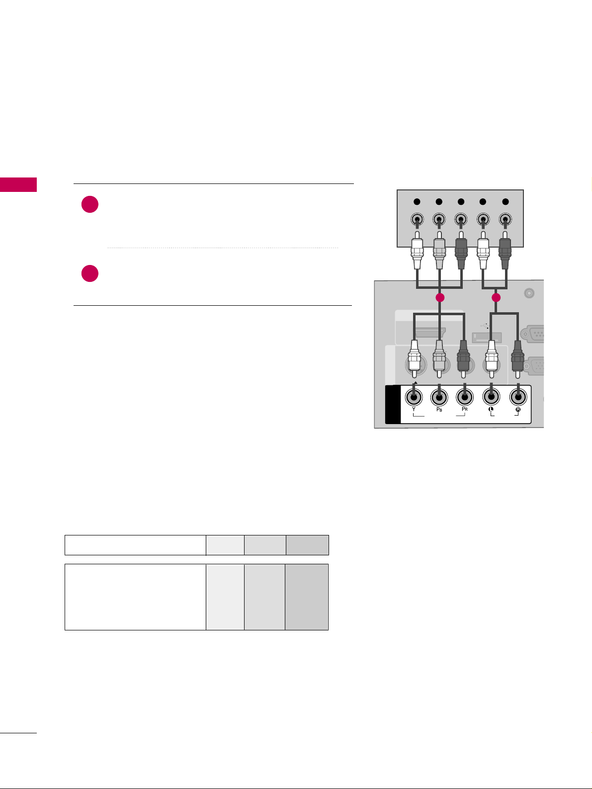
Component Connection
(Except 22LG3DCH)
1. How to connect
Connect the video outputs
(
Y, PB, PR
)
of the digital set-
top box to the
CCOOMMPPOONNEENNTT IINN VVIIDDEEOO
jacks on
the TV. Match the jack colors (Y = green, P
B = blue, and
P
R = red).
Connect the audio output of the digital set-top box to
the
CCOOMMPPOONNEENNTT IINN AAUUDDIIOO
jacks on the TV.
2
1
2. How to use
■
Turn on the digital set-top box.
(
Refer to the owner’s manual for the digital set-top box.
)
■
Select
CCoommppoonneenntt
input source using the
IINNPPUUTT
button
on the remote control.
( )
( )
AUDIO
(RGB/D
AUDIO IN
(RGB/DVI)
HDMI/DVI IN
USB IN
SERVUCE ONLY
VIDEO
MONO
( )
AUDIO
S-VIDEOS-VIDEO
RGB IN (PCRGB IN (PC)
RESET
UPDATE
RS-232C I
(SERVICE O
RS-232C IN
(SERVICE ONLY)
REMOTE
CONTROL OUT
SPEAKER OUT
8
AV IN 1AV IN 1
VIDEO
AUDIO
COMPONENT
IN
Y L RP
B
P
R
RESET
UPDATE
1
2
Y, CB/PB, CR/PR
Supported Resolutions
Horizontal Vertical
Frequency
(
KHz
)
Frequency
(
Hz
)
15.73 59.94
15.73 60.00
31.47 59.94
31.50 60.00
44.96 59.94
45.00 60.00
33.72 59.94
33.75 60.00
Resolution
720x480i
720x480p
1280x720p
1920x1080i
Signal
480i
480p
720p
1080 i
1080 p
Component
Yes
Yes
Yes
Yes
No
HDMI
Yes
Yes
Yes
Yes
Yes
EXTERNAL EQUIPMENT SETUP
22
EXTERNAL EQUIPMENT SETUP
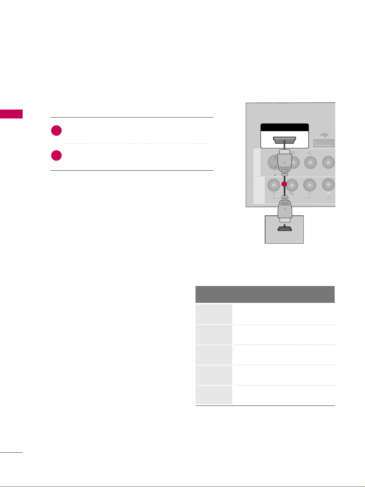
HDMI Connection
Connect the digital set-top box to
HHDDMMII//DDVVII IINN
jack on the TV.
No separate audio connection is necessary.
HDMI supports both audio and video.
1. How to connect
2. How to use
■
Turn on the digital set-top box.
(
Refer to the owner’s manual for the digital set-top box.
)
■
Select
HHDDMMII
input source with using the
IINNPPUUTT
button
on the remote control.
2
1
HDMI-DTV
Horizontal Vertical
Frequency
(
KHz
)
Frequency
(
Hz
)
15.73 59.94
15.73 60.00
31.469 59.94
31.500 60.00
44.96 59.94
45.00 60.00
33.72 59.94
33.75 60.00
67.50 60.00
Resolution
720x480p
1280x720p
1920x1080i
1920x1080p
( )
( )
AUDIO IN
(RGB/DVI)
( )
RGB IN (PC)
RESET
UPDATE
RS-232C IN
(SERVICE ONLY)
REMOTE
CONTROL OUT
SPEAKER OUT
8
HDMI/DVI IN
USB IN
SERVUCE ONL
VIDEO
MONO
( )
AUDIO
S-VIDEOS-VIDEO
RESET
UPUPDATE
AV IN 1AV IN 1
VIDEO
AU
COMPONENT
IN
HDMI-DTV OUTPUT
1
720x480i

EXTERNAL EQUIPMENT SETUP
23
DVI to HDMI Connection
( )
( )
AUDIO IN
(RGB/DVI)
( )
RGB IN (PC)
RESET
UPDATE
RS-232C IN
(SERVICE ONLY)
REMOTE
CONTROL OUT
SPEAKER OUT
8
RESET
UPDATE
AUDIO IN
(RGB/DVI)
AUDIO IN
(RGB/DVI)
HDMI/DVI IN
USB IN
SERVUCE ONLY
VIDEO
MONO
( )
AUDIO
S-VIDEOS-VIDEO
RGB IN (PC)
RS-232C IN
(SERVICE ONLY)
RS-232C IN
(SERVICE ONLY)
AV IN 1AV IN 1
VIDEO
AUDIO
COMPONENT
IN
LR
DVI-DTV OUTPUT
L
R
1
2
GG
A DVI to HDMI cable or adapter is required for this
connection. DVI doesn't support audio, so a separate
audio connection is necessary.
NOTE
!
Connect the DVI output of the digital set-top box to
the
HHDDMMII//DDVVII IINN
jack on the TV.
Connect the audio output of the digital set-top box to
the
AAUUDDIIOO IINN((RRGGBB//DDVVII))
or
AAVV IINN AAUUDDIIOO
jack
on the TV.
1. How to connect
2. How to use
■
Turn on the digital set-top box.
(
Refer to the owner’s man-
ual for the digital set-top box.
)
■
Select the
HHDDMMII
input source on the TV using the
IINNPPUUTT
button on the remote control.
2
1
PILLOW
SPEAKER
RS-232C INRS-232C IN
(SERVICE ONLY)(SERVICE ONLY)
USB INUSB IN
SERVUCE ONLYSERVUCE ONLY
REMOTEREMOTE
CONTROL OUTCONTROL OUT
AV IN 1AV IN 1
AUDIOAUDIO
MONOMONO
( )
RESETRESET
UPDATEUPDATE
AUDIOAUDIO
MONOMONO
( )
LR
DVI-DTV OUTPUT
L
R
ALNORMAL
ERSPEAKER
PILLOW
SPEAKER
HSPEAKER SWITCH
DVI AUDIO INDVI AUDIO IN
AV IN AV IN
VIDEOVIDEO
HDMI/DVI INHDMI/DVI IN
1
2
22LG3DCH model
26/32LG3DCH,
32LG3DC model
EXTERNAL EQUIPMENT SETUP
24
EXTERNAL EQUIPMENT SETUP
DVD SETUP
Component Connection
(Except 22LG3DCH)
Component Input ports
To get better picture quality, connect a DVD player to the component input ports as shown below.
Component ports on the TV
YP
B
P
R
Video output ports
on DVD player
Y
Y
Y
Y
PB
B-Y
Cb
Pb
PR
R-Y
Cr
Pr
Connect the video outputs
(
Y, PB
, PR
)
of the DVD to the
CCOOMMPPOONNEENNTT IINN VVIIDDEEOO
jacks on the TV.
Match the jack colors
(
Y = green, P
B = blue, and PR = red
)
.
Connect the audio outputs of the DVD to the
CCOOMMPPOONNEENNTT IINN AAUUDDIIOO
jacks on the TV.
1. How to connect
2. How to use
■
Turn on the DVD player, insert a DVD.
■
Select the
CCoommppoonneenntt
input source on the TV using the
IINNPPUUTT
button on the remote control.
■
Refer to the DVD player's manual for operating instructions.
2
1
( )
( )
AU
(RG
AUDIO IN
(RGB/DVI)
HDMI/DVI IN
USB IN
SERVUCE ONLY
VIDEO
MONO
( )
AUDIO
S-VIDEOS-VIDEO
RGB INRGB IN (PC)
RESET
UPDATEUPDATE
RS-23
(SERVIC
RS-232C IN
(SERVICE ONLY)
REMOTE
CONTROL OUT
SPEAKER OUT
8
AV IN 1AV IN 1
VIDEO
AUDIO
COMPONENT
IN
Y L RP
B
P
R
RESET
UPDATE
1 2
EXTERNAL EQUIPMENT SETUP
25
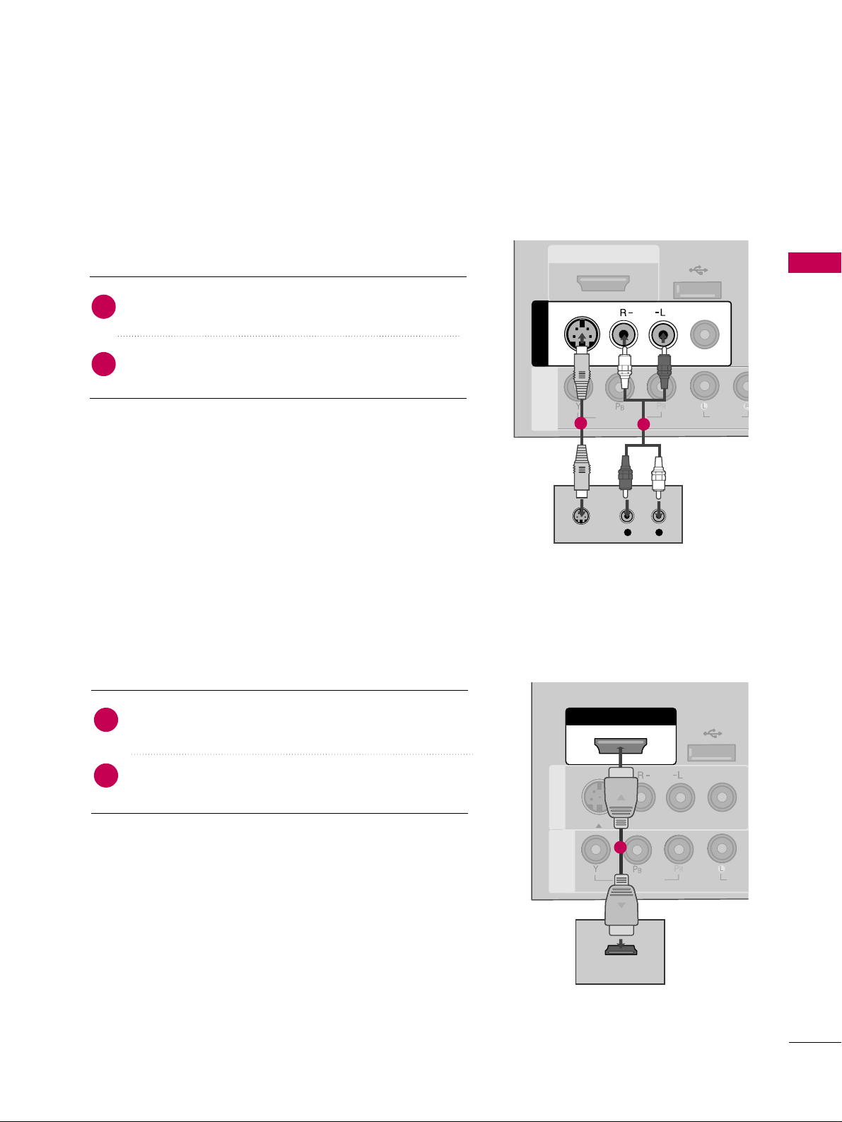
S-Video Connection
(Except 22LG3DCH)
HDMI Connection
Connect the HDMI output of the DVD to the
HHDDMMII//DDVVII IINN
jack on the TV.
No separate audio connection is necessary.
HDMI supports both audio and video.
1. How to connect
2. How to use
■
Select the
HHDDMMII
input source on the TV using the
IINNPPUUTT
button on the remote control.
■
Refer to the DVD player's manual for operating instructions.
2
1
( )
( )
( )
L
R
S-VIDEO
AUDIO
HDMI/DVI IN
USB IN
SERVUCE ONLY
VIDEO
MONO
( )
AUDIO
AV IN 1AV IN 1
VIDEO
AUDIO
COMPONENT
IN
S-VIDEO
1
2
HDMI/DVI IN
USB IN
SERVUCE ONLY
VIDEO
MONO
( )
AUDIO
S-VIDEOS-VIDEO
RESET
UPDUPDATE
AV IN 1AV IN 1
VIDEO
AUDI
COMPONENT
IN
HDMI OUTPUT
1
Connect the S-VIDEO output of the DVD to the
SS --VVIIDDEEOO
input on the TV.
Connect the audio outputs of the DVD to the
AAUUDDIIOO
input jacks on the TV.
1. How to connect
2. How to use
■
Turn on the DVD player, insert a DVD.
■
Select the
AAVV11
input source on the TV using the
IINNPPUUTT
button on the remote control.
■
Refer to the DVD player's manual for operating instructions.
2
1

EXTERNAL EQUIPMENT SETUP
26
EXTERNAL EQUIPMENT SETUP
VCR SETUP
Antenna Connection
■
To avoid picture noise
(
interference
)
, leave an adequate distance between the VCR and TV.
■
If the 4:3 picture format is used; the fixed images on the sides of the screen may remain visible on the
screen. This phenomenon is common to all TVs and is not covered by warranty.
L R
S-VIDEO VIDEO
OUTPUT
SWITCH
ANT IN
ANT OUT
ANTENNA IN
M.P.I.
( )
( )
Wall Jack
Antenna
1
2
Connect the RF antenna out socket of the
VCR to the
AANNTTEENNNNAA IINN
socket on the
TV.
Connect the antenna cable to the RF
antenna in socket of the VCR.
1. How to connect
2. How to use
■
Set VCR output switch to 3 or 4 and then
tune TV to the same channel number.
■
Insert a video tape into the VCR and press
PLAY on the VCR.
(
Refer to the VCR owner’s
manual.
)
2
1
EXTERNAL EQUIPMENT SETUP
27
Composite (RCA) Connection
Connect the
AAUUDDIIOO
/
VVIIDDEEOO
jacks between TV and
VCR. Match the jack colors (Video = yellow, Audio Left
= white, and Audio Right = red)
1. How to connect
2. How to use
■
Insert a video tape into the VCR and press PLAY on the
VCR.
(
Refer to the VCR owner’s manual.
)
■
Select the
AAVV
or
AAVV11
input source on the TV using the
IINNPPUUTT
button on the remote control.
■
If connected to
AAVV IINN22
, select
AAVV22
input source on the TV
(Except 22LG3DCH)
.
1
2. How to use
■
Insert a video tape into the VCR and press PLAY on the
VCR.
(
Refer to the VCR owner’s manual.
)
■
Select the
AAVV11
input source on the TV using the
IINNPPUUTT
button on the remote control.
GG
If you have a mono VCR, connect the audio cable
from the VCR to the
AAUUDDIIOO LL((MMOONNOO))
jack of
the TV.
NOTE
!
ANTENNA IN
M.P.I.
AUDIO
(RGB/
VIDEO
MONO
( )
AUDIO
RGB IN (P
AV IN 1
AV IN 1
VIDEO
AUDIO
COMPONENT
IN
S-VIDEO
L
R
S-VIDEO
VIDEO
OUTPUT
SWITCH
ANT IN
ANT OUT
1
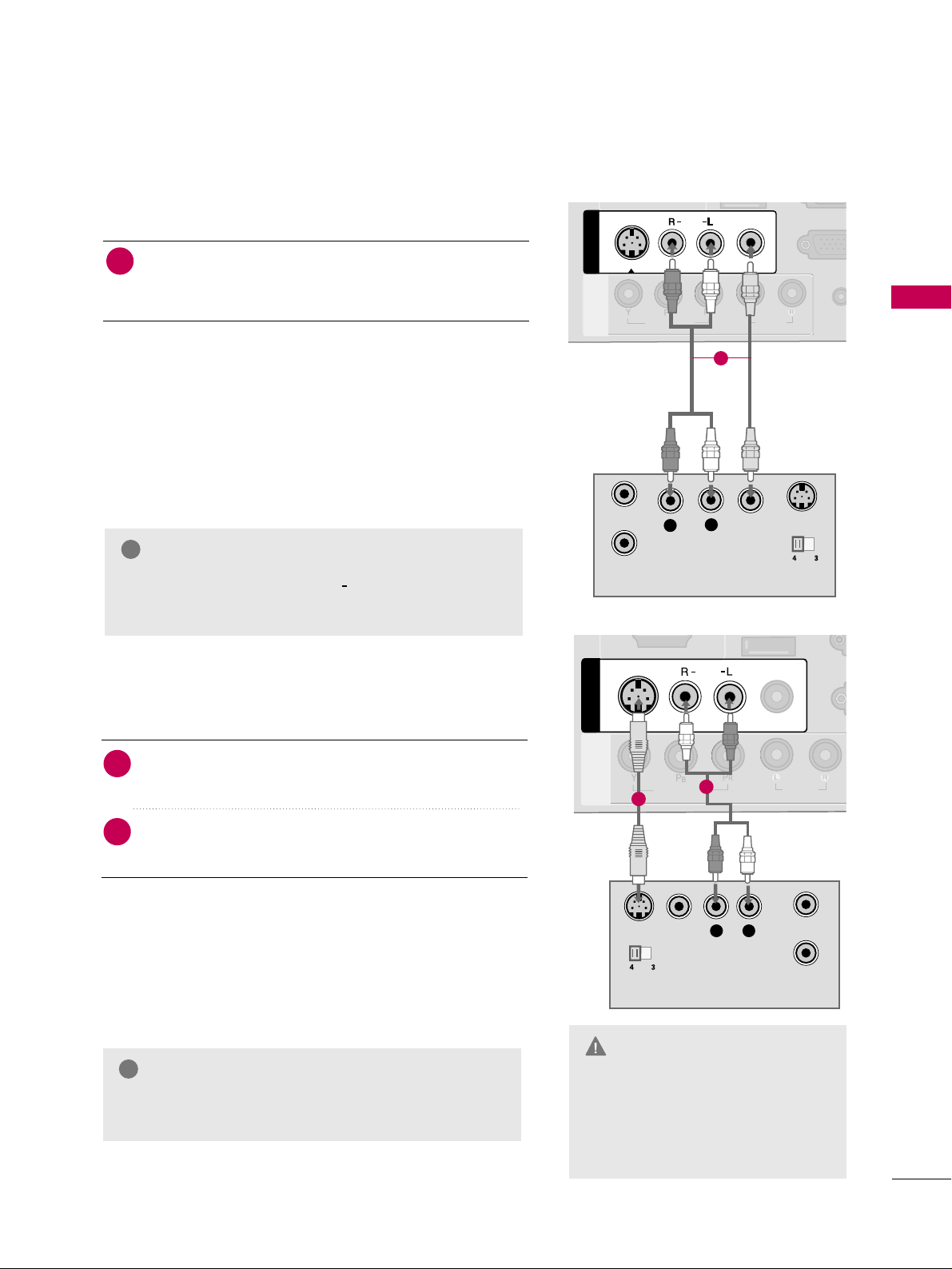
S-Video Connection
(Except 22LG3DCH)
Connect the
SS --VVIIDDEEOO
output of the VCR to the
SS --VVIIDDEEOO
input on the TV.
Connect the audio outputs of the VCR to the
AAUUDDIIOO
input jacks on the TV.
1. How to connect
2
1
ANTENNA IN
M.P.I.
VIDEO
MONO
( )
AUDIO
R
AV IN 1AV IN 1
VIDEO
AUDIO
COMPONENT
IN
S-VIDEO
( )
L
R
S-VIDEO VIDEO
OUTPUT
SWITCH
ANT IN
ANT OUT
1
2
GG
Do not connect to both Video
and S-Video at the same time. In
the event that you connect both
Video and the S-Video cables,
only the S-Video will work.
CAUTION
GG
S-Video provides better quality than composite. Use
it when available.
NOTE
!
EXTERNAL EQUIPMENT SETUP
28
EXTERNAL EQUIPMENT SETUP
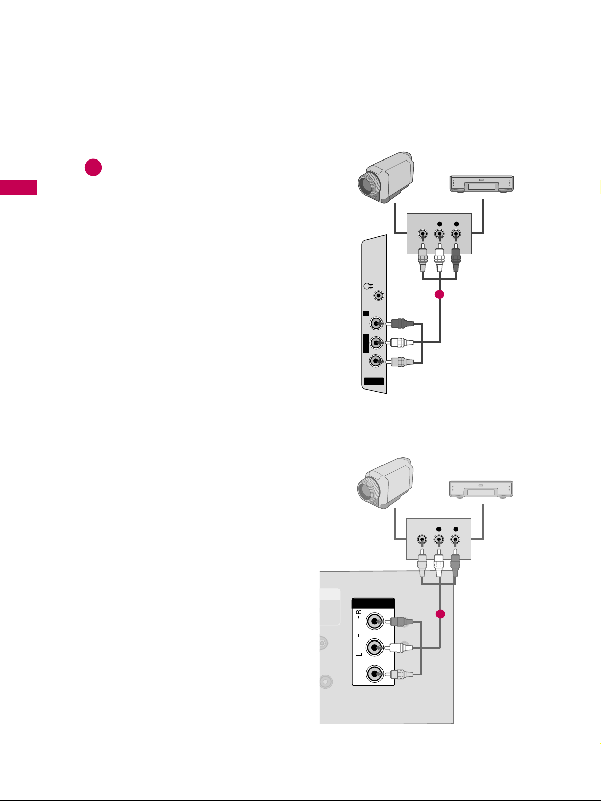
OTHER A/V SOURCE SETUP
R
AV IN 2
L/MONO
R
AUDIO
VIDEO
H/P
L R
VIDEO
Camcorder
Video Game Set
Connect the
AAUUDDIIOO
/
VVIIDDEEOO
jacks
between TV and external equipment.
Match the jack colors
.
(
Video = yellow, Audio Left = white, and
Audio Right = red
)
1. How to connect
2. How to use
■
Select the
AAVV22
input source on the TV using the
IINNPPUUTT
button on the remote control.
(Except
22LG3DCH)
■
If connected to
AAVV IINN
or
AAVV IINN11
input, select
the
AAVV
or
AAVV11
input source on the TV.
■
Operate the corresponding external equipment.
1
1
PILLOW
SPEAKER
NRS-232C IN
Y)(SERVICE ONLY)
USB IN
SERVUCE ONLY
EMOTEREMOTE
TROL OUTCONTROL OUT
RESETRESET
UPDATEUPDATE
N
VIDEOVIDEO
AUDIOAUDIO
MONOMONO
( )
L R
VIDEO
PILLOW
SPEAKER
RS-232C IN
(SERVICE ONLY)
USB IN
SERVUCE ONLY
REMOTE
CONTROL OUT
AV IN
VIDEO
AUDIO
MONO
( )
NORMAL
SPEAKER
PILLOW
SPEAKER
SPEAKER SWITCH
RESET
UPDATE
DVI AUDIO IN
DVI AUDIO INDVI AUDIO IN
NORMAL
SPEAKER
PILLOW
SPEAKER
SPEAKER SWITCH
AV IN AV IN
Video Game Set
1
Camcorder
22LG3DCH model
26/32LG3DCH,
32LG3DC model
EXTERNAL EQUIPMENT SETUP
29
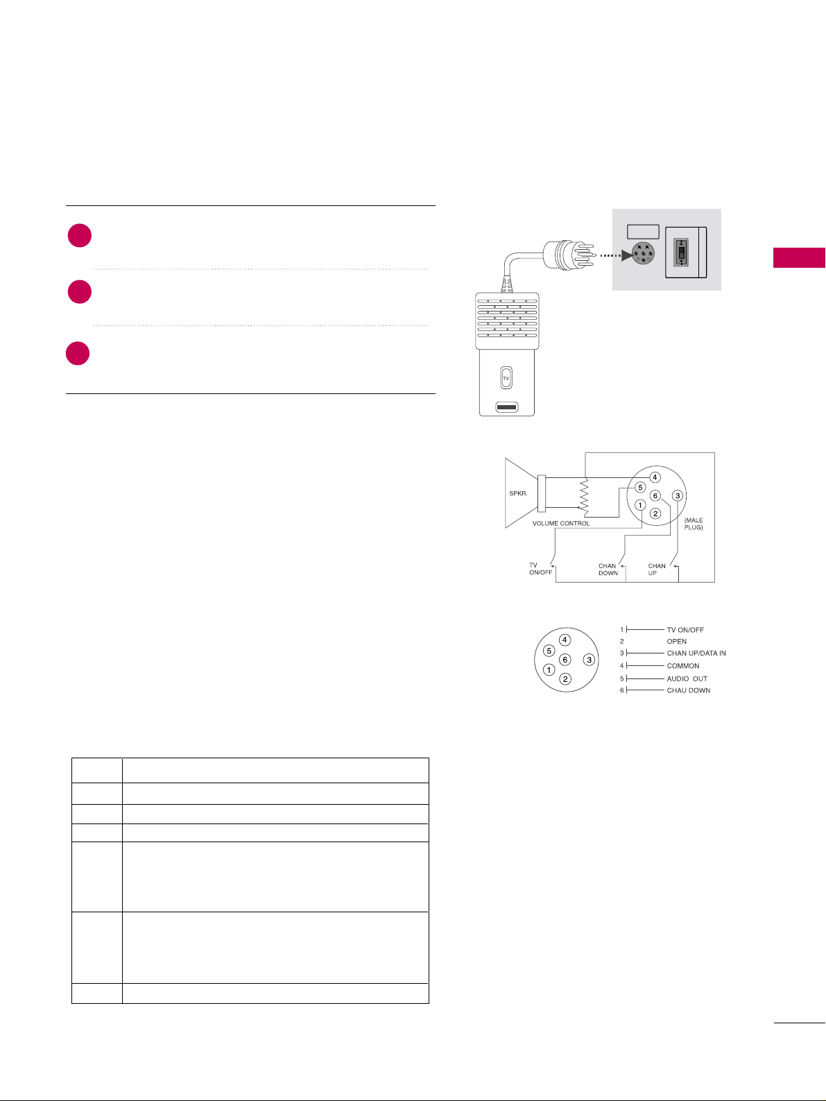
PILLOW SPEAKER SETUP
■
Connect a pillow speaker to the LCD TV/Monitor.
PILLOWPILLOW
SPEAKERSPEAKER
NORMALNORMAL
SPEAKERSPEAKER
PILLOWPILLOW
SPEAKERSPEAKER
SPEAKER SWITCHSPEAKER SWITCH
(Except 32LG3DC)
1. How to connect
Connect the
PPIILLLLOOWW SSPPEEAAKKEERR
output jack on the
back of the TV.
Connect an acccessory pillow speaker or wired remote
control unit to this 6-pin jack.
Select
PPIILLLLOOWW SSPPEEAAKKEERR
on the rear panel of the
TV.
2
1
3
■
NOTE:
If the pillow speaker switch is set to Pillow Speaker, no
sound will be heard from the TV speakers. Also, Auto Volume will
be grayed out and not accessible on the Sound menu.
Use a pillow speaker that is a UL recognized pendant control
bearing the warning:
“Risk of fire if used in oxygen enriched atmosphere. Keep pen-
dant control away from oxygen equipment.”
Controlling the TV with Serial Data
The TV is capable of being controlled by a single-wire, serial data
signal. This is a LG patented technology and is being implemented
by certain brands of “smart” pillow speakers.
Pillow Speaker Interface
This connector furnishes three control lines and an audio output.
A patient-pendant remote control, or entertainment audio and
nurse call system may be connected here. All lines are isolated
from the AC power line and earth ground. (Optoisolators isolate
the control lines, and a transformer isolates the audio. There are
no relays or inductive components in the control lines.)
Controlling the TV with Mechanical Switches
Pin 4(common) is momentarily connected to pin
1, 3, or 6 via push-action switches to control
On/Off and Channel Up/Down. These pins are
at +13volts DC(when measured from pin4) with
the switches open. Current draw is 8 mA when a
switch is closed. (This operation is identical to
previous LG models using the 5-Wire Interface
except that only +7 volts DC was supplied and
current draw was only 2.5 mA.)
pin No.
1
2
3
4
5
6
External TV On/Off switch.
(Not used.)
External Channel Up switch or Data in.
Common connection for control, data, and
audio output. Impedance to earth ground is a
10-meg resistor in parallel with a 1100 pf
capacitor.
Isolated audio output. Nominal 14-ohm source
impedance with short circuit protection.
Intended for a pillow speaker with a low-impe
ance pad-type volume control.
External Channel Down switch.
Purpose
EXTERNAL EQUIPMENT SETUP
30
EXTERNAL EQUIPMENT SETUP
PC SETUP
Horizontal Vertical
Frequency
(
KHz
)
Frequency
(
Hz
)
31.469 70.08
31.469 70.08
31.469 59.94
37.879 60.31
48.363 60.00
47.776 59.87
47.712 60.01
47.720 59.799
47.130 59.65
GG
To get the the best picture quality, adjust the PC
graphics card to 1360x768.
GG
Depending on the graphics card, DOS mode may
not work if a HDMI to DVI Cable is in use.
GG
In PC mode, there may be noise associated with the
resolution, vertical pattern, contrast or brightness.
If noise is present, change the PC output to anoth-
er resolution, change the refresh rate to another
rate or adjust the brightness and contrast on the
PICTURE menu until the picture is clear.
GG
Avoid keeping a fixed image on the screen for a
long period of time. The fixed image could become
permanently imprinted on the screen.
GG
The synchronization input form for Horizontal and
Vertical frequencies is separate.
GG
Depending on the graphics card, some resolution
settings may not allow the image to be positioned
on the screen properly.
NOTES
!
Supported Display Specifications
(RGB-PC, HDMI-PC)
Resolution
720x400
1360x768
640x350
640x480
800x600
1024x768
1366x768
1280x768
* Only RGB-PC mode
This TV provides Plug and Play capability, meaning that the PC adjusts automatically to the TV's settings.
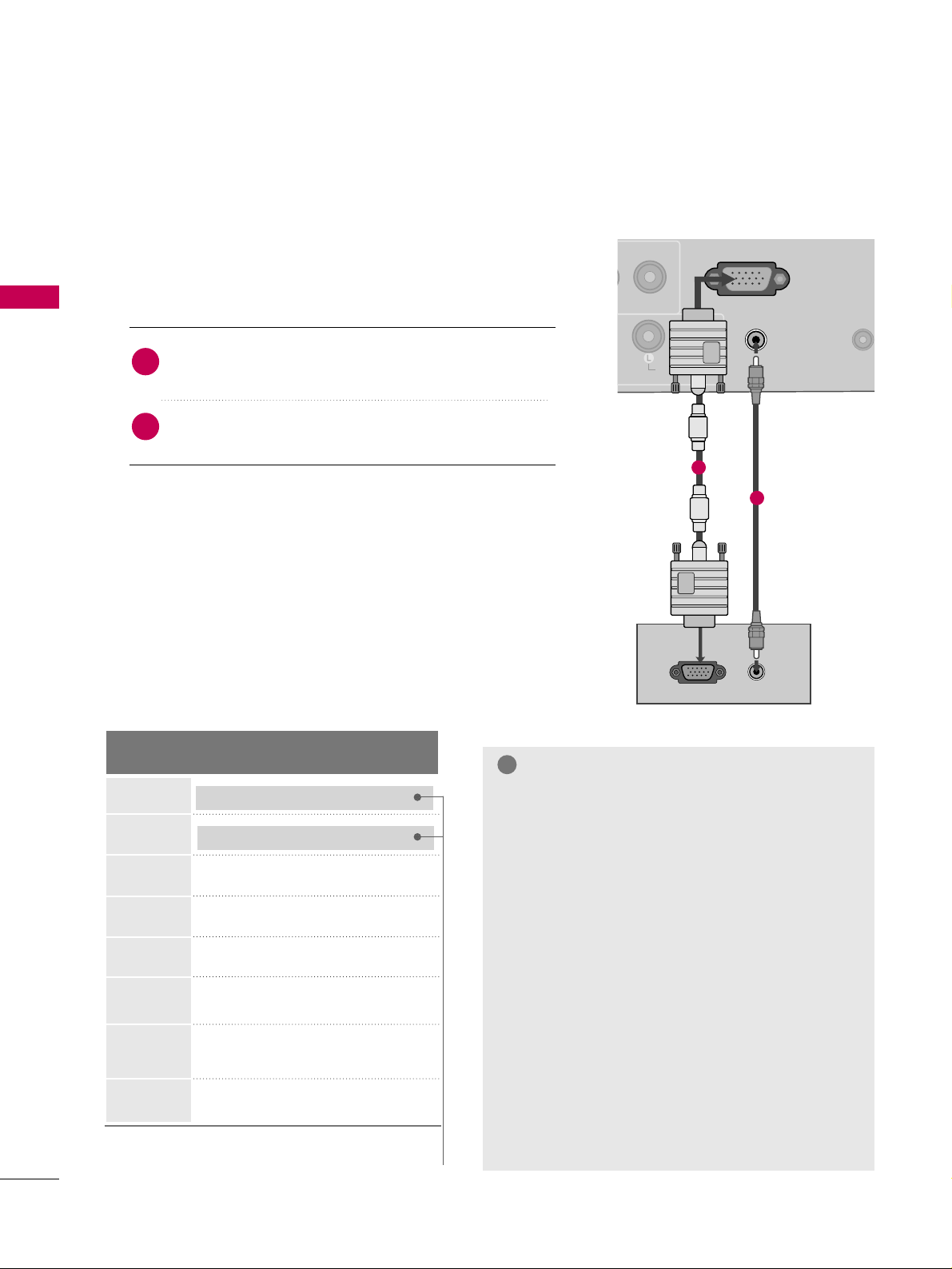
VGA (D-Sub 15 pin) Connection
(Except 22LG3DCH)
RGB OUTPUT
AUDIO
AUDIO IN
(RGB/DVI)
AUDIO IN
(RGB/DVI)
VIDEO
NO
( )
RGB IN (PC)RGB IN (PC)
REMOT
CONTROL
AUDIOAUDIO
1
2
2. How to use
■
Turn on the PC and the TV.
■
Select the
RR GGBB
input source on the TV using the
IINNPPUUTT
button on the remote control.
Connect the VGA output of the PC to the
RR GGBB
II NN
((
PPCC
))
jack on the TV.
Connect the PC audio output to the
AAUUDDIIOO IINN
((
RRGGBB//DDVVII
))
jack on the TV.
1. How to connect
2
1
EXTERNAL EQUIPMENT SETUP
31
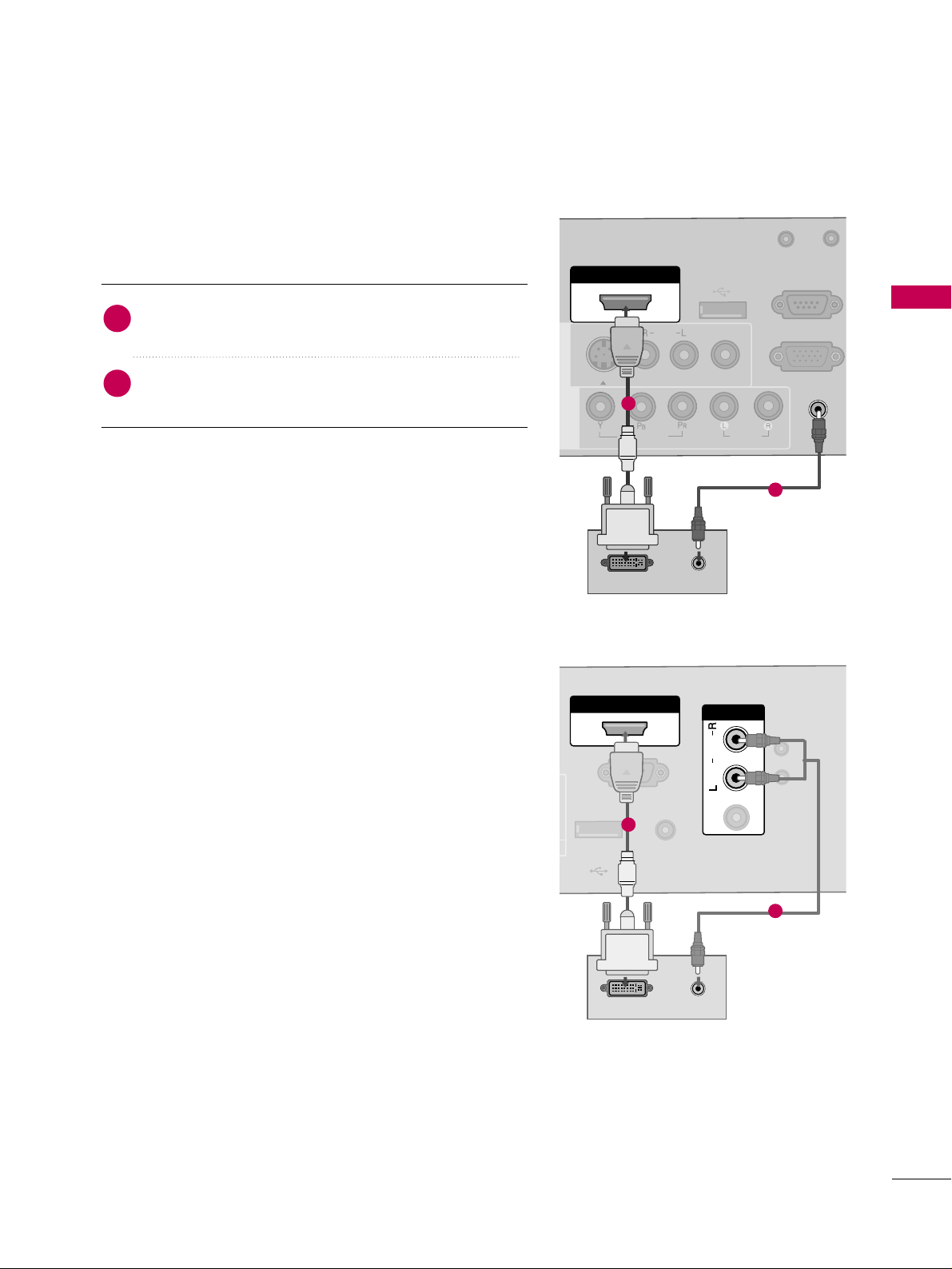
DVI to HDMI Connection
( )
( )
( )
AUDIO IN
(RGB/DVI)
AUDIO IN
(RGB/DVI)
HDMI/DVI IN
USB IN
SERVUCE ONLY
VIDEO
MONO
( )
AUDIO
S-VIDEOS-VIDEO
RGB IN (PC)
UPDATE
RS-232C IN
(SERVICE ONLY)
AV IN 1AV IN 1
VIDEOVIDEO
AUDIOAUDIO
COMPONENT
IN
DVI-PC OUTPUT AUDIO
1
2
2. How to use
■
Turn on the PC and the TV.
■
Select the
HHDDMMII
input source on the TV using the
IINNPPUUTT
button on the remote control.
Connect the DVI output of the PC to the
HHDDMMII//DDVVII
IINN
jack on the TV.
Connect the PC audio output to the
AAUUDDIIOO II NN
((RRGGBB//DDVVII))
or
AAVV IINN AAUUDDIIOO
jack on the TV.
1. How to connect
2
1
PILLOW
SPEAKER
RS-232C INRS-232C IN
(SERVICE ONLY)(SERVICE ONLY)
USB INUSB IN
SERVUCE ONLYSERVUCE ONLY
REMOTEREMOTE
CONTROL OUTCONTROL OUT
AV IN 1AV IN 1
AUDIOAUDIO
MONOMONO
( )
UPDATEUPDATE
RESETRESET
AUDIOAUDIO
MONOMONO
( )
DVI-PC OUTPUT AUDIO
DVI AUDIO INDVI AUDIO IN
LNORMAL
RSPEAKER
PILLOW
SPEAKER
SPEAKER SWITCH
HDMI/DVI INHDMI/DVI IN
AV IN AV IN
VIDEOVIDEO
1
2
22LG3DCH model
26/32LG3DCH,
32LG3DC model
EXTERNAL EQUIPMENT SETUP
32
EXTERNAL EQUIPMENT SETUP
Screen Setup for PC mode
(Except 22LG3DCH)
Select the desired resolution.
1024 x 768
1280 x 768
1360 x 768
1366 x 768
Auto config.
Resolution
G
Position
Size
Phase
Reset
Screen
Move
Prev.
MENU
1
ADJUST
3
4
2
ENTER
RETURN
Select
RReessoolluuttiioonn
.
Selecting Resolution
You can choose the resolution in RGB mode.
The
PPoossiittiioonn
,
PPhhaassee
, and
SSiizzee
can also be adjusted.
Press the
AADDJJUUSSTT
button.
Return to TV viewing.
■
You can also adjust
SSccrreeeenn((RRGGBB--PPCC))
in the
PPIICCTTUURREE
menu.
EXTERNAL EQUIPMENT SETUP
33
Auto Configure
Automatically adjusts picture position and minimizes image instability. After adjustment, if the image is still
not correct, try using the manual settings or a different resolution or refresh rate on the PC.
Select
AAuuttoo ccoonnffiigg..
.
Auto config.
G
Resolution
Position
Size
Phase
Reset
Screen
Move
Prev.
MENU
To Set
3
2
Select
YYeess
.
4
ENTER
Start Auto Configuration.
ENTER
Press the
AADDJJUUSSTT
button.
1
• If the position of the image is still not
correct, try Auto adjustment again.
• If picture needs to be adjusted again
after Auto adjustment in RGB, you can
adjust the
PPoossiittiioonn
,
SSiizzee
or
PPhhaassee
.
Yes No
ADJUST

EXTERNAL EQUIPMENT SETUP
34
EXTERNAL EQUIPMENT SETUP
Adjustment for screen Position, Size, and Phase
If the picture is not clear after auto adjustment and especially if characters are still trembling, adjust the picture
phase manually.
This feature operates only in RGB mode.
Make appropriate adjustments.
Auto config.
Resolution
Position
G
Size
Phase
Reset
GF
D
E
Screen
Move
Prev.
MENU
3
ENTER
4
RETURN
■
PPoossiittiioonn
: This function is to adjust pic-
ture to left/right and up/down as you
prefer.
■
SSiizzee
: This function is to minimize any
vertical bars or stripes visible on the
screen background. And the horizontal
screen size will also change. The
SSiizzee
adjustment range is
--3300
~
3300
.
■
PPhhaa ssee
: This function allows you to
remove any horizontal noise and clear or
sharpen the image of characters. The
PPhhaassee
adjustment range is
--3322
~
3311
.
Press the
AADDJJUUSSTT
button.
Select
PPoossiittiioonn
,
SSiizzee
, or
PPhhaassee
.
1
ADJUST
2
Return to TV viewing.

EXTERNAL EQUIPMENT SETUP
35
Screen Reset (Reset to original factory values)
Returns
PPoossiittiioonn
,
SSiizzee
, and
PPhhaassee
to the default factory settings.
This feature operates only in RGB mode.
3
ENTER
Select
RReesseett
.
1
ADJUST
2
Select
YYeess
.
4
ENTER
Auto config.
Position
Resolution
Size
Phase
Reset
G
Screen
Move
Prev.
MENU
Initialize Settings.
Yes No
Press the
AADDJJUUSSTT
button.
WATCHING TV / CHANNEL CONTROL
36
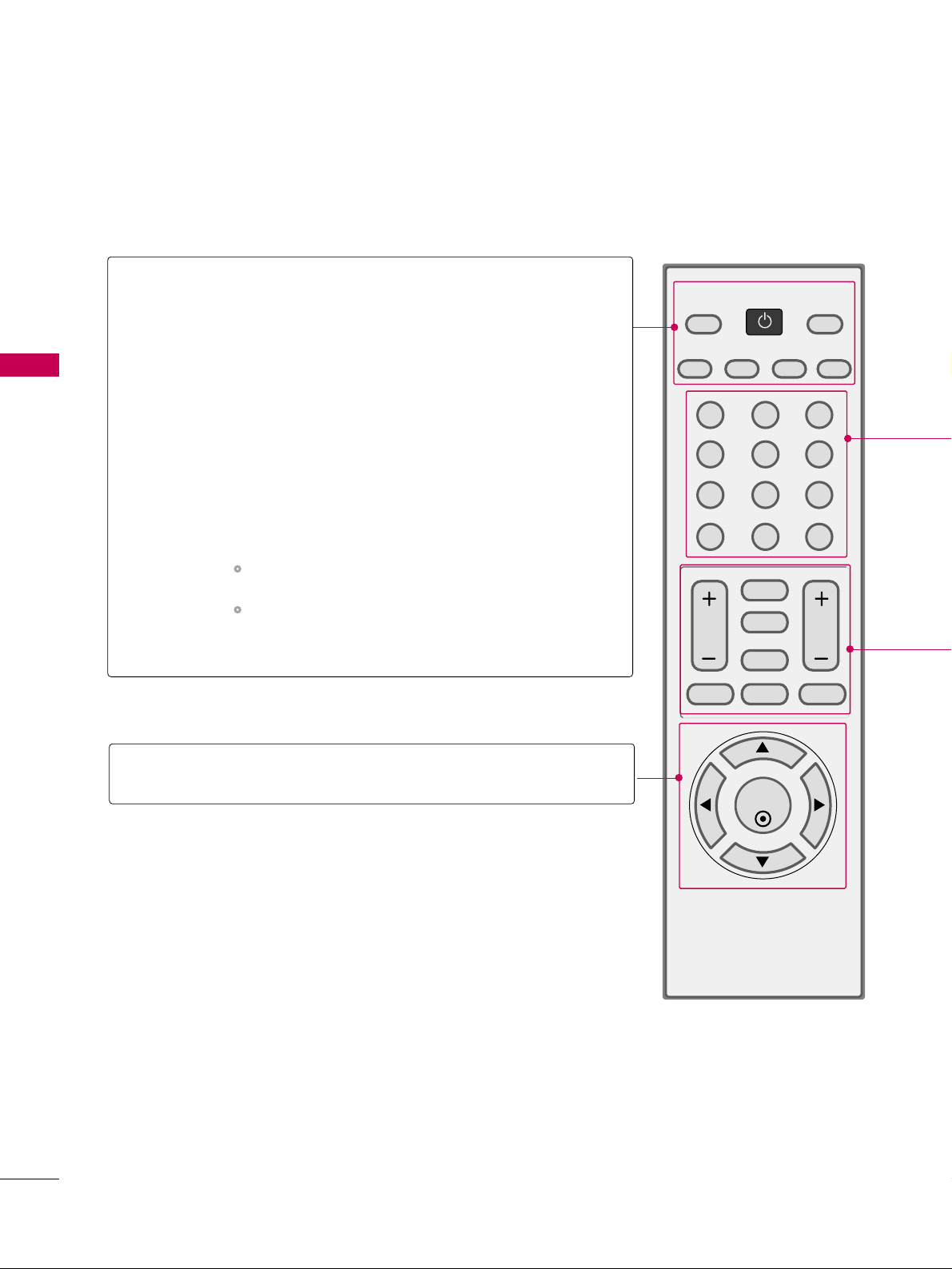
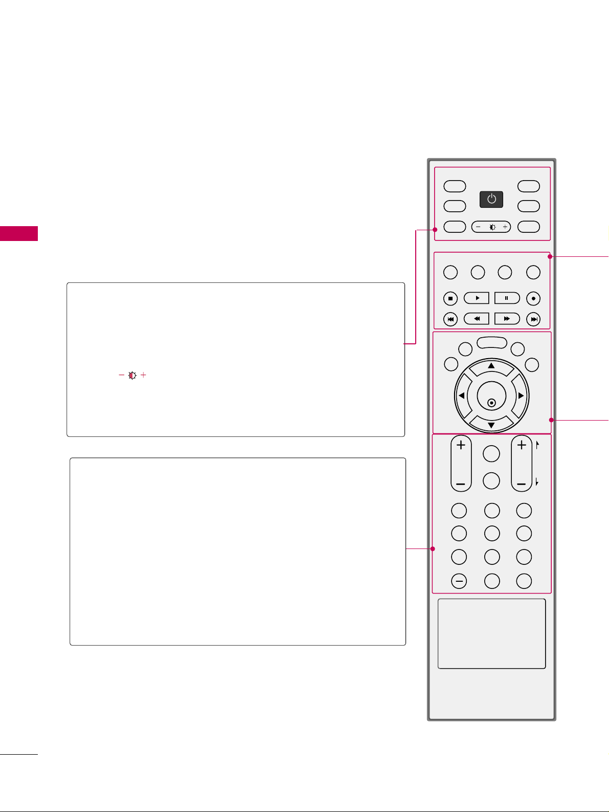
REMOTE CONTROL FUNCTIONS
WATCHING TV / CHANNEL CONTROL
When using the remote control, aim it at the remote control sensor on the TV.
123
456
78
0-
9
VOL CH
ENTER
POWER
MUTE
MENU
ADJUST
RETURN
CC
SAP
FLASHBK
PICTURE
SOUND
RATIO
TV
INPUT
TIMER
POWER
TV
INPUT
PICTURE
SOUND
SAP
RATIO
Turns your TV on or off.
In AV1-2, Component, RGB, and HDMI input sources, screen
returns to the last TV channel.
External input modes rotate in regular sequence: TV, AV1-
2, Component, RGB, and HDMI.
Selects the factory preset picture depend on the viewing
environment.
GG
pp..5511
Selects the factory preset sound for type of program.
GG
pp..6611
Analog mode: Selects MTS sound (Mono, Stereo, or a
SAP).
GG
pp..6677
DTV mode: Changes the audio language.
Change the aspect ratio.
GG
pp..4488
THUMBSTICK
(Up/Down/Left
Right/ENTER)
Navigate the on-screen menus and adjust the system set-
tings to your preference.
(Only 32LG3DC)
WATCHING TV / CHANNEL CONTROL
37
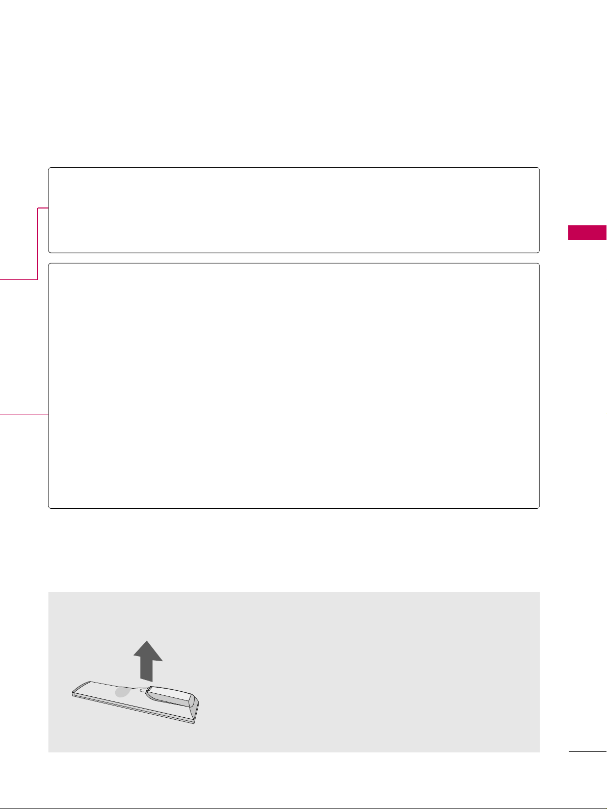
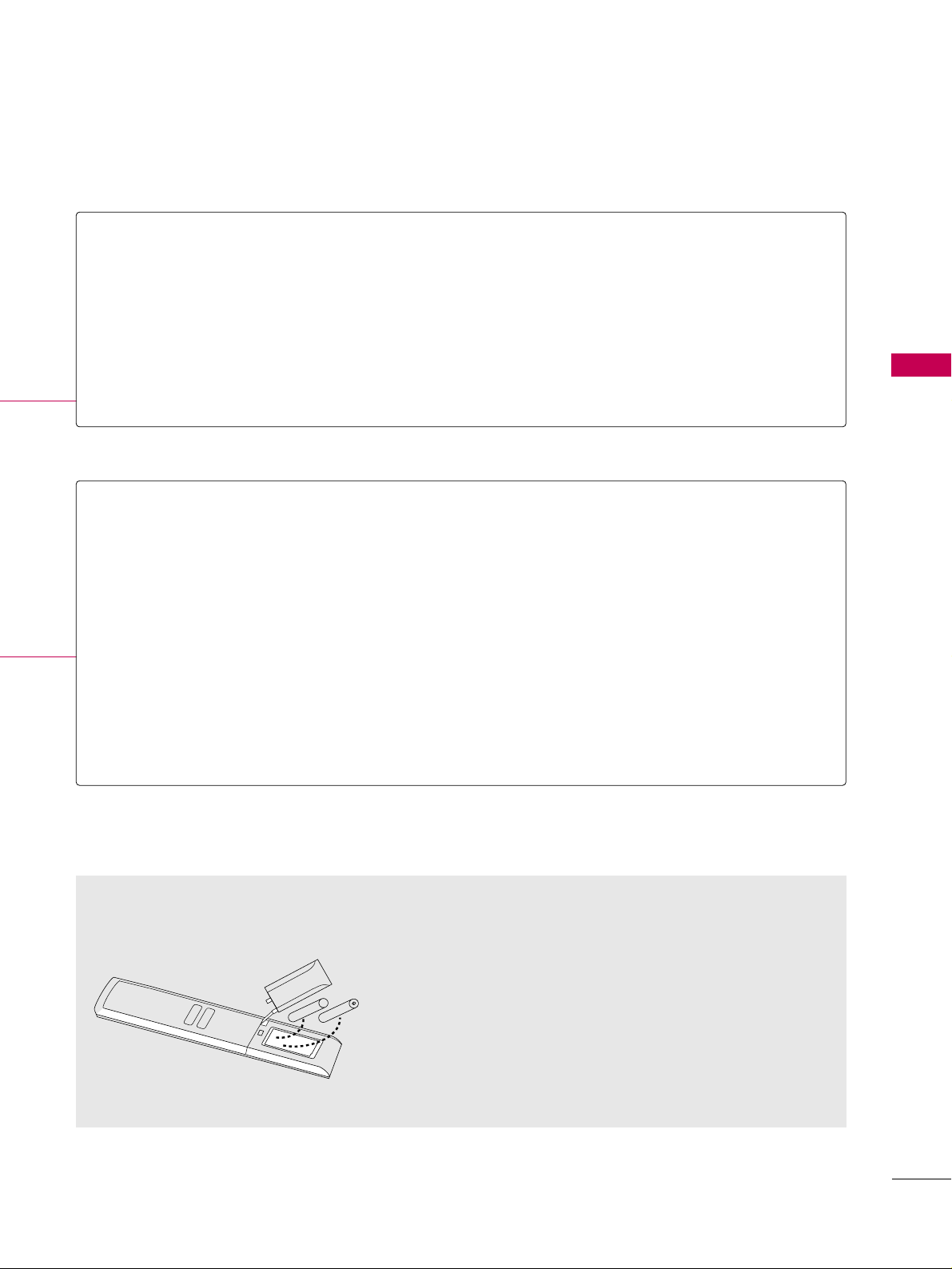
Installing Batteries
■
Open the battery compartment cover on the back side and install
the batteries matching correct polarity
(
+with +,-with -
)
.
■
Install two 1.5V AAA batteries. Don’t mix old or used batteries with
new ones.
■
Close cover.
NUMBER button
— (DASH)
FLASHBK
Used to enter a program number for multiple program channels such as 2-1, 2-2, etc.
Tune to the last channel viewed.
VOLUME UP
/DOWN
TIMER
CC
MUTE
CHANNEL
UP/DOWN
ADJUST
MENU
RETURN
Increase/decrease the sound level.
Select the amount of time before your TV turns off automatically.
GG
pp..7766
Select a closed caption.
GG
pp..7700
Switch the sound on or off.
GG
pp..4411
Select available channels.
Adjust the screen resolution, position, size and phase.
GG
pp..3322 -- pp..3355
Displays the main menu.
Allows the user to move return one step in an interactive application or other user interac-
tion function.
WATCHING TV / CHANNEL CONTROL
38
INSTALLER REMOTE CONTROL FUNCTIONS
WATCHING TV / CHANNEL CONTROL
ENTER
TVTV
INPUT
INPUT MODE
DVD
MULTI
EXIT
VOL
EZ SOUND
INFO
SWAP
EZ PIC
TIMER
MUTE
CH
SAP
CC
RATIO
MENU
VCR
POWER
123
456
789
0
FLASH
BACK
PAGE
TV INPUT/INPUT
POWER
MULTI
MODE
Select available input sources.
Turns your TV or any other programmed
equipment On or Off, depending on mode.
Selects available auxiliary input sources.
Adjusts picture brightness.
Selects remote operating mode: TV, VCR, or DVD. Select
these other operating modes for remote to operate external
devices.
VOLUME
UP/DOWN
CHANNEL
UP/DOWN/PAGE
TIMER
MUTE
NUMBER
Buttons (0 - 9)
— (DASH)
FLASHBK
Increases/decreases the sound level.
Selects available channels found with Auto tuning.
Moves to next available page.
Sets the amount of time before the TV automatically
turns itself Off.
Switches the sound on or off.
Use to enter a program number or channels.
Dash for multiple channels such as 9-1, 9-2, etc.
Returns to the previously viewed channel.
Use the MODE button to select TV and put installer remote into TV operating
mode.
Notes: This remote is not supplied with the TV. This typical LG multi-brand
remote control is shown for reference.
Follow the instructions provided in the Installer menu section to configure the
TV’s features.
All features shown may not be available on all TVs.
LG Multi-brand Remote Control
WATCHING TV / CHANNEL CONTROL
39
EZ PIC
EZ SOUND
SWAP
INFO
VCR/DVD
BUTTONS
Selects the factory preset picture appropriate for the viewing environment.
Sets the appropriate sound for the program’s content.
Exchanges the main/sub images in Twin picture mode.
While watching a TV program, will display program information on top of the screen.
Info feature is not functional for Aux sources.
Control some video cassette recorders or DVD players. (“RECORD” is not functional in DVD
mode.) Set up for VCR recording: Once, Regularly, Weekly, Off. (“RECORD” button only).
MENU
CC
EXIT
RATIO
SAP
THUMBSTICK
(Up/Down/Left
Right/ENTER)
Brings up the main menu to the screen.
Enters or exits a Panel Menu in the TV Guide on-screen menu system.
Selects a closed caption option: Off, CC1
~ 4, Text1 ~ 4.
Clears all on-screen displays and returns to TV viewing from any TV menu.
Adjusts the picture aspect ratio.
Selects MTS sound:
Mono, Stereo, and SAP in Analog mode.
Changes the audio language in DTV mode.
Use to navigate on-screen menus / adjust the system settings to your requirements.
Installing Batteries in Installer Remote Control
■
Remove the battery compartment cover on the back side by slid-
ing the cover downward until the batteries are exposed and can be
removed. Install new batteries matching correct polarity as shown
(+ with + and - with -). Slide cover back into position to close
compartment.
■
Install two high-quality 1.5V AAA batteries. Never mix old or used
batteries with new ones. Replace cover.
AAA +
+ AAA
WATCHING TV / CHANNEL CONTROL
40
WATCHING TV / CHANNEL CONTROLWATCHING TV / CHANNEL CONTROL
NOTE
!
GG
If you intend to be away on vacation, disconnect the power plug from the wall power outlet.
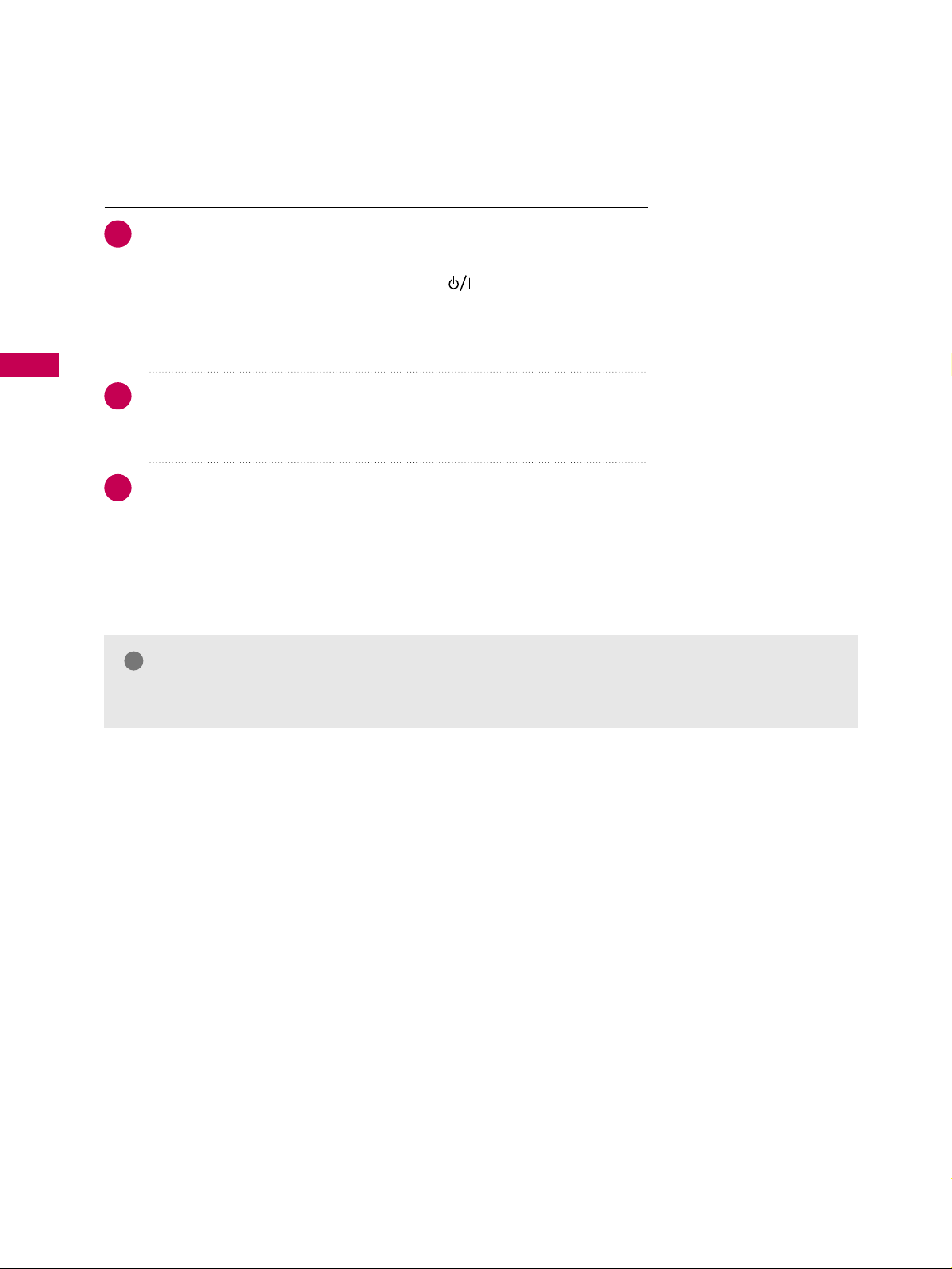
TURNING ON TV
First, connect power cord correctly.
At this moment, the TV switches to standby mode.
■
In standby mode to turn TV on, press the button on the TV or press
the
PPOOWWEERR
button on the remote control.
■
Note: Only for 32LG3DCH the TV also turn on with
CCHH ((++
or
--))
button on the remote.
Select the viewing source by using the
IINNPPUUTT
button on the remote control.
■
This TV is programmed to remember which power state it was last set to,
even if the power cord is out.
When finished using the TV, press the
PPOOWWEERR
button on the remote con-
trol. The TV reverts to standby mode.
1
2
3

WATCHING TV / CHANNEL CONTROL
41
Press the
CCHH ((++
or
--))
or
NNUUMMBBEERR
buttons to select a channel number.
1
VOLUME ADJUSTMENT
CHANNEL SELECTION
Press the
VVOOLL ((++
or
--))
button to adjust the volume.
If you want to switch the sound off, press the
MMUUTTEE
button.
You can cancel the Mute function by pressing the
MMUUTTEE
or
VVOOLL ((++
or
--))
button.
Adjust the volume to suit your personal preference.
1
2
3

WATCHING TV / CHANNEL CONTROL
42
WATCHING TV / CHANNEL CONTROL
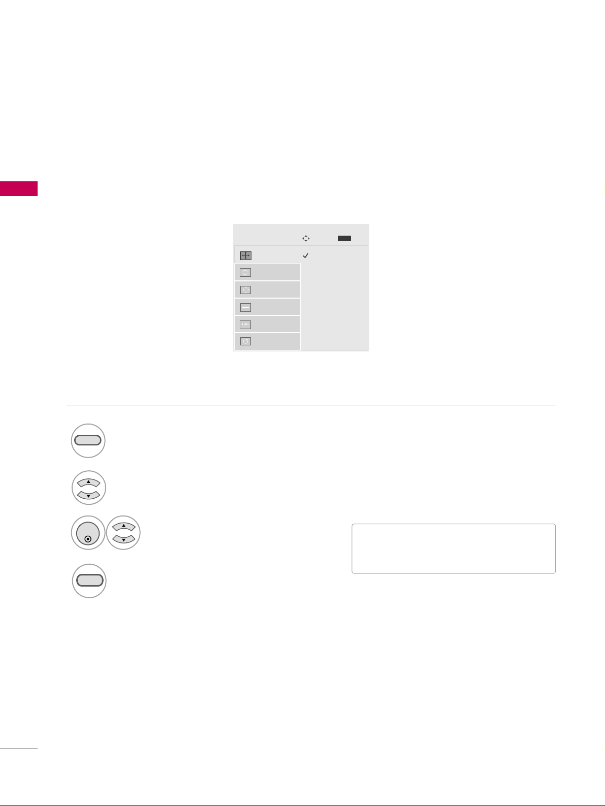
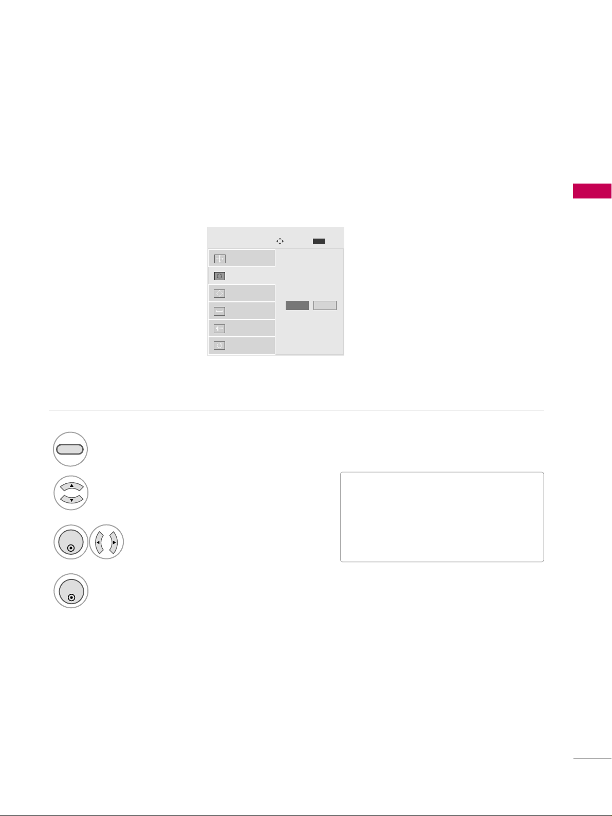
ON-SCREEN MENUS SELECTION
Your TV's OSD (On Screen Display) may differ slightly from that shown in this manual.
Display each menu.
Select a menu item.
Enter to the pop up menu.
1
MENU
3
2
ENTER
ENTER
Return to TV viewing.
4
MENU
Enter
Move
CHANNEL
CHANNEL
TIME
PICTURE
OPTION
AUDIO
LOCK
Enter
Move
Aspect Ratio : 16:9
Picture Mode : Standard
• Backlight 80
• Contrast 90
• Brightness 50
• Sharpness 60
• Color 60
• Tint 0
PICTURE
E
Enter
Move
Auto Volume : Off
Clear Voice : On
Balance 0
Sound Mode : Standard
•
SRS TruSurround XT:
Off
• Treble 50
• Bass 50
• Reset
AUDIO
E
LR
Enter
Move
Clock :
Feb/21/2008/ 2:10 AM
Off Time : Off
On Time : Off
Sleep Timer : Off
Auto Sleep : Off
TIME
Enter
Move
Lock System : Off
Set Password
Block Channel
Movie Rating
TV Rating-Children
TV Rating-General
Downloadable Rating
Input Block
LOCK
RG
Auto Tuning
Manual Tuning
Channel Edit
Channel Label
Enter
Move
Language : English
Caption : Off
OPTION
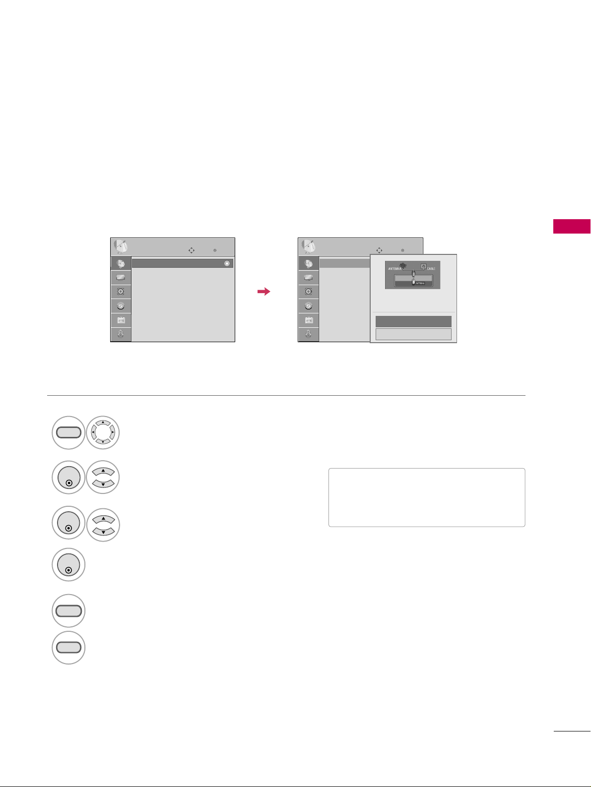
WATCHING TV / CHANNEL CONTROL
43
CHANNEL SETUP
Auto Scan (Auto Tuning)
Automatically finds all channels available through antenna or cable inputs, and stores them in memory on the
channel list.
Run Auto Tuning again after any Antenna/Cable connection changes.
Select
CCHHAANNNNEELL
.
Select
AAuuttoo TTuunniinngg
.
Select
YYeess
.
Run
AAuuttoo ttuunniinngg
.
1
MENU
3
2
ENTER
ENTER
4
ENTER
■
A password is required to gain access to
Auto Tuning menu if the Lock System is
turned on.
5
RETURN
Return to the previous menu.
MENU
Return to TV viewing.
Enter
Move
CHANNEL
Auto Tuning
Manual Tuning
Channel Edit
Channel Label
Enter
Move
CHANNEL
Auto Tuning
Manual Tuning
Channel Edit
Channel Label
Press ‘Yes’ button to begin
auto tuning.
Yes
No
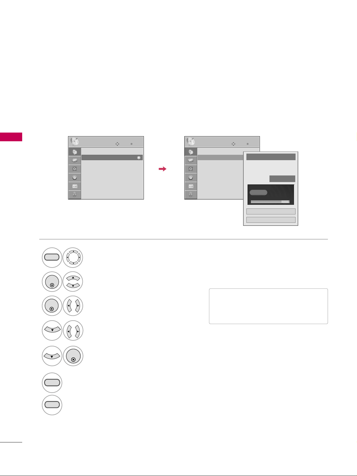
WATCHING TV / CHANNEL CONTROL
44
WATCHING TV / CHANNEL CONTROL
Select
CCHHAANNNNEELL
.
1
MENU
2
ENTER
If selecting DTV or CADTV input signal, you can view the on-screen signal strength monitor to see the quality
of the signal being received.
Add/Delete Channel (Manual Tuning)
Select
MMaannuuaall TTuunniinngg
.
Select
DDIIGGIITTAALL
or
AANNAALLOOGG
.
Select channel you want to add
or delete.
3
ENTER
4
Select
AAdddd
or
DDeelleettee
.
5
ENTER
■
A password is required to gain access to
Manual Tuning menu if the Lock System
is turned on.
6
RETURN
Return to the previous menu.
MENU
Return to TV viewing.
Enter
Move
CHANNEL
Enter
Move
CHANNEL
Auto Tuning
Manual Tuning
Channel Edit
Channel Label
Channel
Select channel type and
RF-channel number.
FF
DIGITAL
GG
FF
2
GG
Close
Delete
DIGITAL 2-1
Bad Normal Good
Auto Tuning
Manual Tuning
Channel Edit
Channel Label
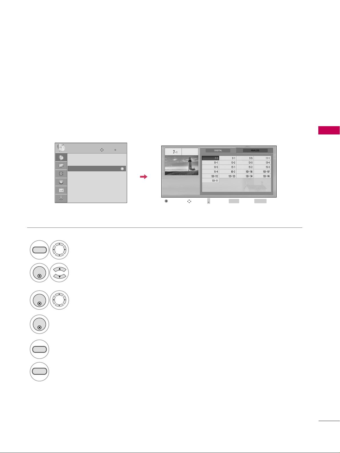
WATCHING TV / CHANNEL CONTROL
45
Select a channel.
Select channel you want to add or delete.
3
ENTER
4
ENTER
A custom list can be created by toggling each channel on or off with ENTER button. The channels in the Custom
List are displayed in black and the channels deleted from the Custom List are displayed in gray.
Once a channel is highlighted you can add or delete the channel by referring to the small window at the top-
right corner of the screen.
Channel Editing
Select
CCHHAANNNNEELL
.
1
MENU
2
ENTER
Select
CChhaannnneell EEddiitt
.
RETURN
Return to TV viewing.
Return to the previous menu.
5
MENU
Add/Delete
Move Page
CH
Move
Previous
RETURN
EXIT
MENU
Enter
Move
CHANNEL
Auto Tuning
Manual Tuning
Channel Edit
Channel Label
+

WATCHING TV / CHANNEL CONTROL
46
WATCHING TV / CHANNEL CONTROL
CHANNEL LABEL
Choose preset labels for your channels.
If a channel label is provided on the signal from the broadcasting station, the TV displays a short name for a
channel even if you didn't preset a label for the channel.
Enter
Move
CHANNEL
Auto Tuning
Manual Tuning
Channel Edit
Channel Label
Enter
Move
CHANNEL
Auto Tuning
Manual Tuning
Channel Edit
Channel Label
Logo
FF
Disney
GG
Channel
DIGITAL 2-1
Close
Select
CCHHAANNNNEELL
.
Select
CChhaannnneell LLaabbeell
.
Select Channel.
1
MENU
3
2
ENTER
ENTER
Select the appropriate logo for the channel.
5
Select a channel to set logo.
4
6
RETURN
Return to the previous menu.
MENU
Return to TV viewing.
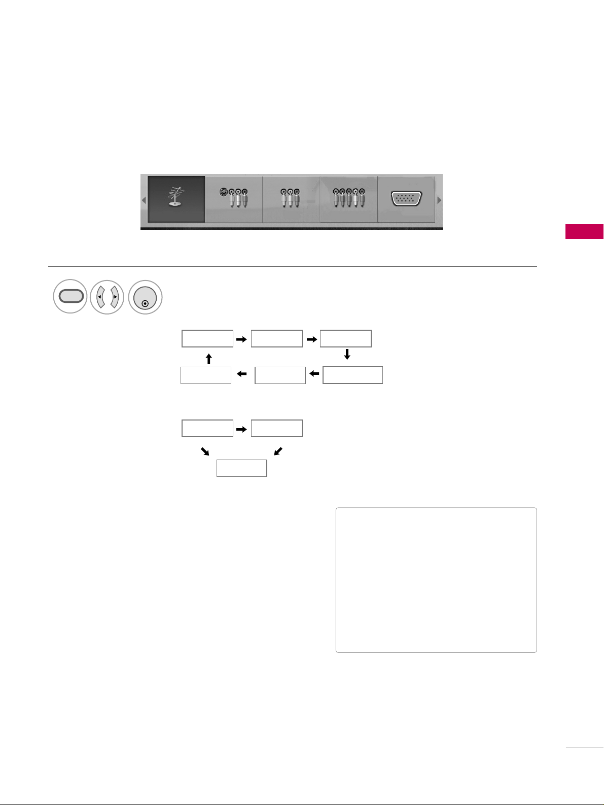
WATCHING TV / CHANNEL CONTROL
47
INPUT LIST
Select the desired input source.
1
INPUT
TV AV1 AV2
Component
HDMI RGB
TV AV1 AV2 Component RGB
ENTER
■
TT VV
: Select it to watch over-the-air, cable
and digital cable broadcasts.
■
AAVV11--22
: Select them to watch a VCR or
other external equipment.
■
CCoommppoonnee nntt
: Select them to watch
DVD or a Digital set-top box.
■
RR GGBB
: Select it to view PC input.
■
HHDDMMII
: Select them to watch high defin-
ition devices.
TV AV
HDMI
For 26/32LG3DCH
32LG3DC
For 22LG3DCH
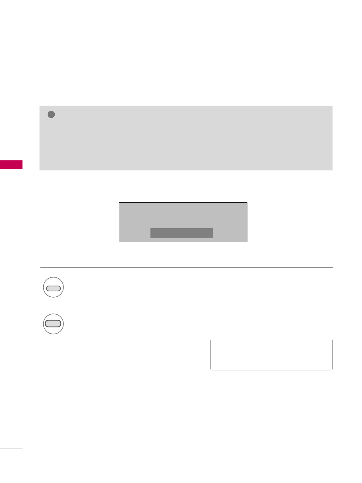
PICTURE CONTROL
48
PICTURE SIZE (ASPECT RATIO) CONTROL
PICTURE CONTROL
This feature lets you choose the way an analog picture with a 4:3 aspect ratio is displayed on your TV.
■
RGB input source use 4:3 or 16:9 aspect ratio.
NOTE
!
GG
If a fixed image is displayed on the screen for a long time, the image could become imprinted on the
screen and remain visible. This phenomenon is rare on LCDs, but is possible when the image is on the
screen for a very long time. This phenomenon is common to all manufacturers and is not covered by
warranty. When watching video that does not fill the screen, any after-image from the black bars will
normally dissipate after a few minutes.
Press the
RRAATTIIOO
button repeatedly to select the picture options
:
SSeett BByy PPrrooggrraamm,, 44::33,, 1166::99,, FFuullll
(Only 22LG3DCH)
,, ZZoooomm11,, ZZoooomm22,,
JJuusstt SSccaann
.
1
RATIO
2
RETURN
Return to TV viewing.
1166::99
■
You can also adjust
AAssppeecctt RRaattiioo
in
the
PPIICCTTUURREE
menu.
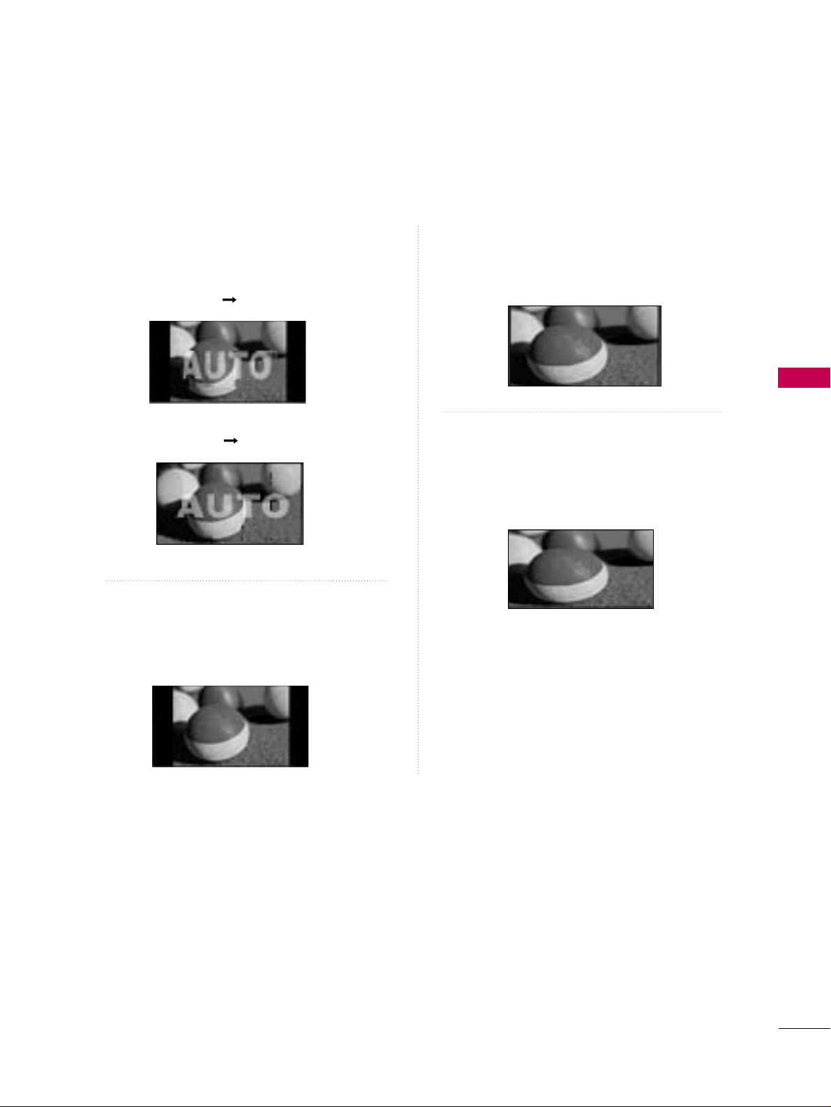
PICTURE CONTROL
49
Set by program
Selects the proper picture proportion to match
the source’s image.
4:3
Choose 4:3 when you want to view a picture
with an original 4:3 aspect ratio.
16 : 9
Adjust the picture horizontally, in a linear pro-
portion to fill the entire screen.
Full
(Only 22LG3DCH)
When TV receives the wide screen signal, it will lead
you to adjust the picture horizontally or vertically,
in a linear proportion, to fill the entire screen fully.
(4:3 4:3)
(16:9 16:9)

PICTURE CONTROL
50
PICTURE CONTROL
Zoom 1
Choose Zoom 1 when you want to view the pic-
ture without any alteration. However, the top and
bottom portions of the picture will be cropped.
Zoom 2
Choose Zoom 2 when you want the picture to be
altered, both vertically extended and cropped.
The picture taking a halfway trade off between
alteration and screen coverage.
Just Scan
Normally the edges of video signals are cropped
1-2%. Just Scan turns off this cropping and
shows the complete video.
Notes: If there is noise on the edges of the original
signal, it will be visible when Just Scan is activated.
JJuusstt SSccaann
operates only with
DTV/CADTV/HDMI-DTV/DVI-DTV
(720p/1080i/1080p),
Component(720p/1080i) input sources.

PICTURE CONTROL
51
PRESET PICTURE SETTINGS
Picture Mode - Preset
There are factory presets for picture settings available in the user menus. You can use a preset, change each
setting manually.
1
PICTURE
Press the
PPIICCTTUURREE
button repeatedly to select the picture options
:
VViivviidd
,
SSttaannddaarrdd
,
CCiinneemmaa
,
SSppoorrtt
,
GGaammee
and
EExxppeerrtt11--22
.
■
You can also adjust
PPiiccttuurree MMooddee
in
the
PPIICCTTUURREE
menu.
Return to TV viewing.
2
RETURN
VViivviidd
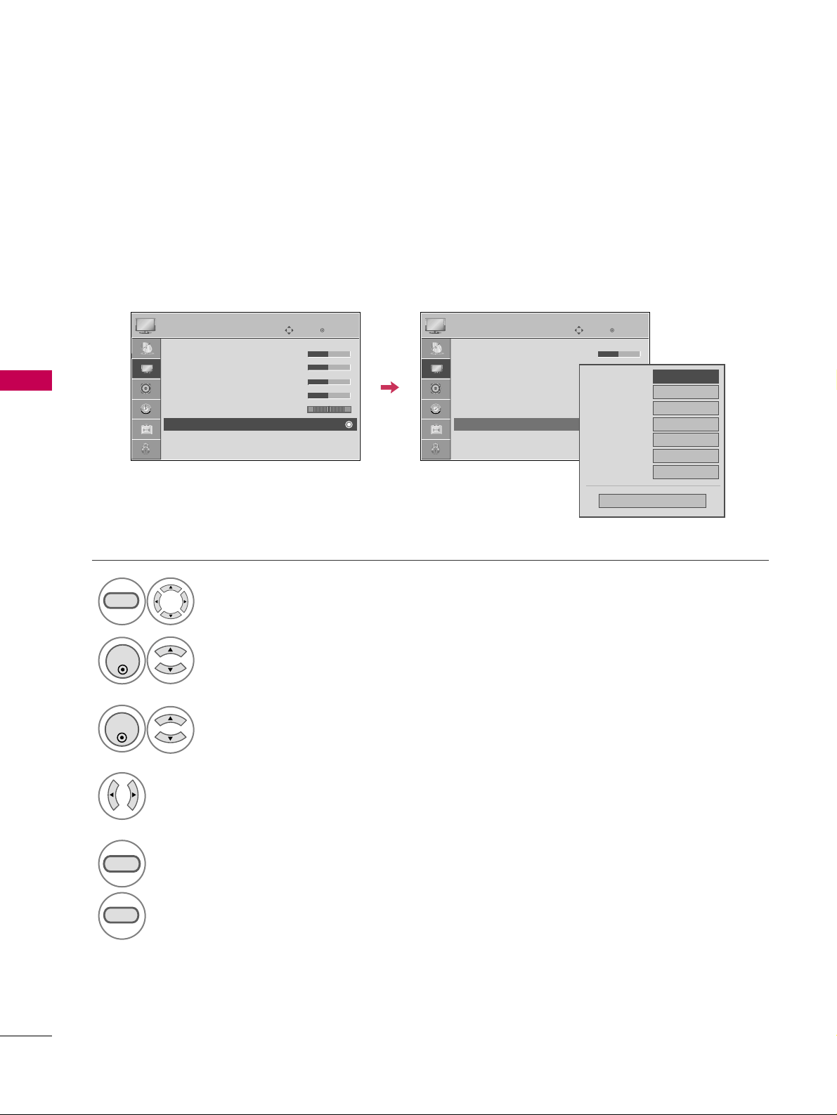
PICTURE CONTROL
52
PICTURE CONTROL
Color Tone - Preset
Choose one of three automatic color adjustments. Set to warm to enhance hotter colors such as red, or set to
cool to see less intense colors with more blue.
Select
PPIICCTTUURREE
.
Select
CCoolloorr TTeemmppeerraattuurree
.
1
MENU
3
ENTER
Select
CCooooll
,
MMeeddiiuumm
, or
WWaarrmm
.
4
Select
AAddvvaanncceedd CCoonnttrrooll
.
2
ENTER
5
RETURN
Return to the previous menu.
MENU
Return to TV viewing.
Enter
Move
PICTURE
EE
RG
• Contrast 50
• Brightness 50
• Sharpness 50
• Color 50
• Tint 0
• Advanced Control
• Reset
Screen (RGB-PC)
Enter
Move
PICTURE
E
RG
• Contrast 50
• Brightness 50
• Sharpness 50
• Color 50
• Tint 0
• Advanced Control
• Reset
Screen (RGB-PC)
Color Temperature
FF
Medium
GG
Fresh Contrast
Off
Fresh Color
Off
Noise Reduction
Auto
Gamma
Medium
Black Level
Medium
Real Cinema
Off
Close
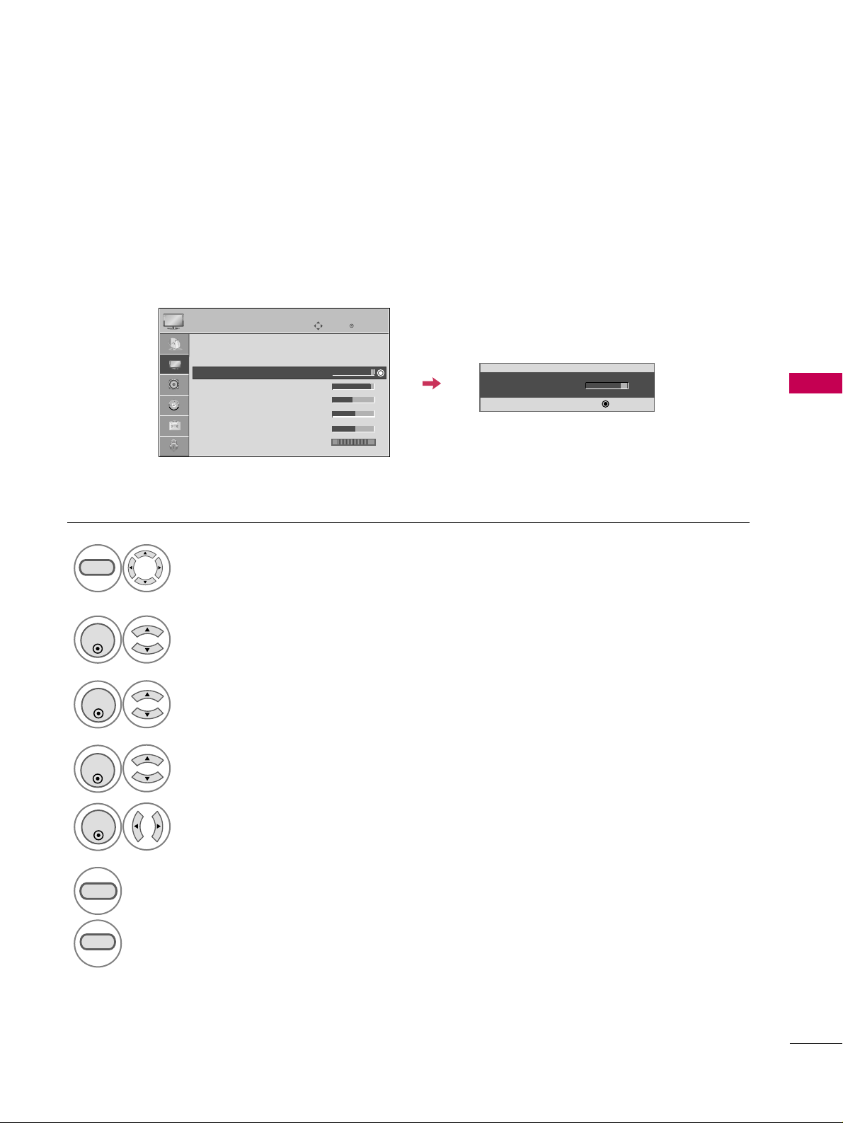
PICTURE CONTROL
53
MANUAL PICTURE ADJUSTMENT
Picture Mode - User Mode
Adjust the picture appearance to suit your preference and viewing situations.
Select
PPIICCTTUURREE
.
Make appropriate adjustments.
Select
BBllaacckklliigghhtt,, CCoonnttrraasstt,, BBrriigghhttnneessss,,
SShhaarrppnneessss,, CCoolloorr,, oorr TTiinntt..
1
MENU
Select
PPiiccttuurree MMooddee
.
2
ENTER
Select
VViivviidd
,
SSttaannddaarrdd
,
CCiinneemmaa
,
SSppoorrtt
, or
GGaammee
.
3
ENTER
4
ENTER
5
ENTER
6
RETURN
Return to the previous menu.
Return to TV viewing.
Enter
Move
PICTURE
E
Aspect Ratio : 16:9
Picture Mode : Standard
• Backlight 90
• Contrast 90
• Brightness 50
• Sharpness 60
• Color 60
• Tint 0
• Backlight 80
EE
EE
EE
EE
Enter
RG
MENU
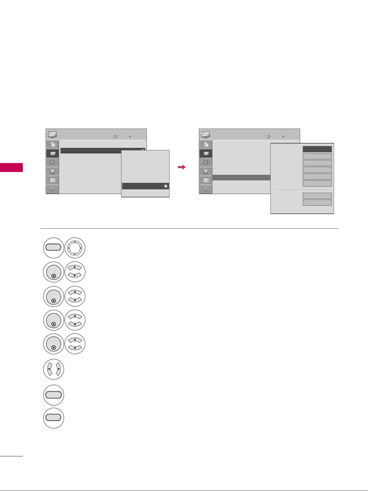
PICTURE CONTROL
54
PICTURE CONTROL
Picture Mode - Expert Control
Select your desired menu option.
Select
PPIICCTTUURREE
.
Select
PPiiccttuurree MMooddee
.
Select
EExxppeerrtt CCoonnttrrooll
.
Select
EExxppeerrtt11
or
EExxppeerrtt22
.
1
MENU
3
2
ENTER
ENTER
4
ENTER
5
ENTER
Make appropriate adjustments.
6
EExxppeerrtt11
and
EExxppeerrtt22
allow you set you own custom settings.
7
RETURN
Return to the previous menu.
Return to TV viewing.
Enter
Move
PICTURE
E
Aspect Ratio : 16:9
Picture Mode : Standard
• Backlight
• Contrast 90
• Brightness 50
• Sharpness 60
• Color 60
• Tint 0
RG
Enter
Move
PICTURE
Vivid
Standard
Cinema
Sport
Game
Expert1
Expert2
E
MENU
• Contrast 90
• Brightness 50
• Sharpness 60
• Color 60
• Tint 0
• Expert Control
• Reset
Screen (RGB-PC)
RG
FF
Off
GG
Fresh Contrast
Noise Reduction
Off
Gamma
Medium
Black Level
Auto
Off
Real Cinema
Color Standard
HD
White Balance
Normal
Red Contrast
50
E
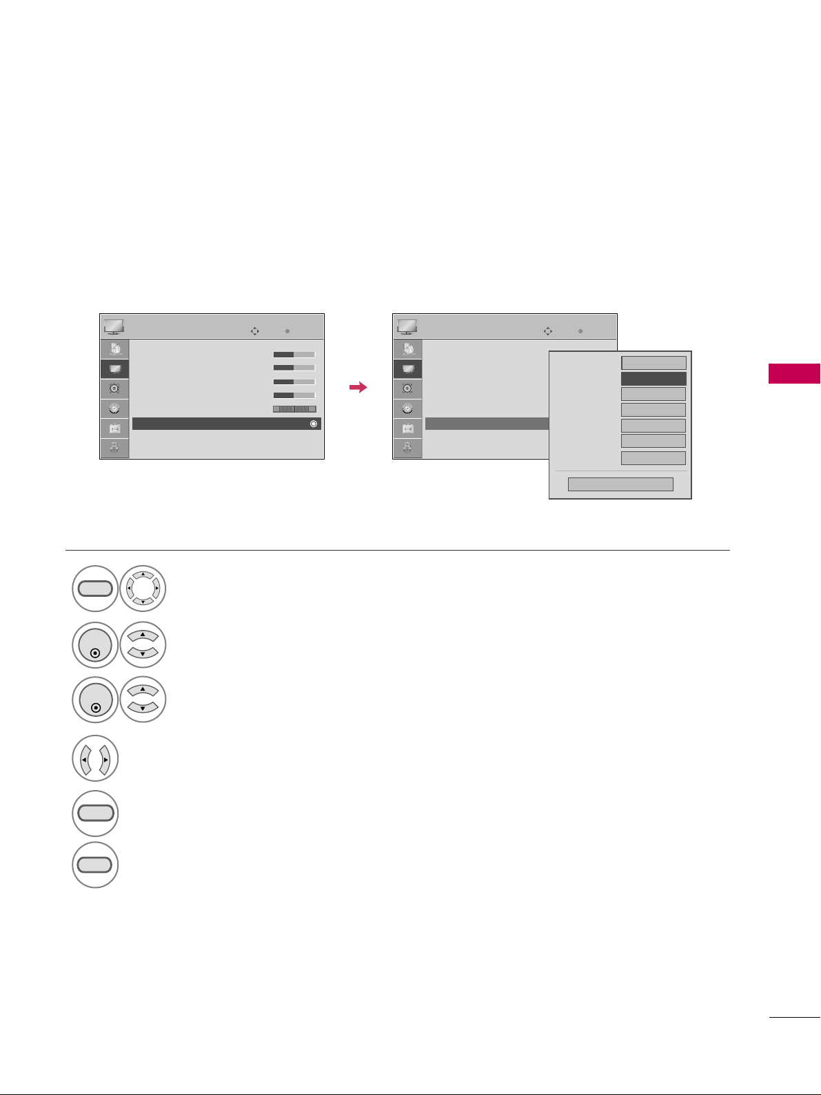
PICTURE CONTROL
55
PICTURE IMPROVEMENT SETTINGS
Fresh Contrast: Optimizes the contrast automatically according to the brightness of the reflection.
Fresh Color: Adjusts the color of the reflection automatically to reproduce as close as possible natural colors.
Noise Reduction: Removes interference up to the point where it does not damage the original picture.
Gamma: High gamma values display whitish images and low gamma values display high contrast images.
Select
PPIICCTTUURREE
.
Select
AAddvvaanncceedd CCoonnttrrooll
.
Select
FFrreesshh CCoonnttrraasstt
,
FFrreesshh CCoolloorr
,
NNooiissee RReedduuccttiioonn
, or
GGaammmmaa
.
1
MENU
3
2
ENTER
ENTER
5
RETURN
Return to the previous menu.
Return to TV viewing.
Select your desired options.
4
Enter
Move
PICTURE
E
RG
• Contrast 50
• Brightness 50
• Sharpness 50
• Color 50
• Tint 0
• Advanced Control
• Reset
Screen (RGB-PC)
Enter
Move
PICTURE
E
RG
• Contrast 50
• Brightness 50
• Sharpness 50
• Color 50
• Tint 0
• Advanced Control
• Reset
Screen (RGB-PC)
MENU
Color Temperature
FF
Medium
GG
Fresh Contrast
Off
Fresh Color
Off
Noise Reduction
Auto
Gamma
Medium
Black Level
Medium
Real Cinema
Off
Close
Medium
FF
Off
GG
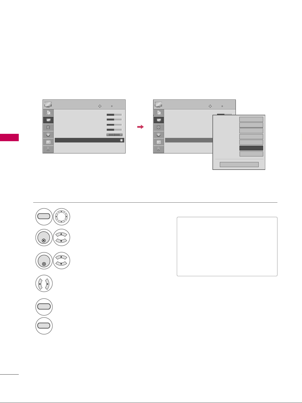
PICTURE CONTROL
56
PICTURE CONTROL
ADVANCED CONTROL - BLACK (DARKNESS) LEVEL
Adjusting the contrast and the brightness of the screen using the black level of the screen.
This feature is disable in DTV and RGB mode.
Select
PPIICCTTUURREE
.
Select
AAddvvaanncceedd CCoonnttrrooll
.
Select
BBllaacckk LLeevveell
.
1
MENU
3
2
ENTER
ENTER
Select
LLooww
or
HHiigghh
.
4
■
LLooww
: The reflection of the screen gets
darker.
■
HHiigghh
: The reflection of the screen gets
brighter.
■
AAuuttoo
: Realizing the black level of the
screen and set it to High or Low auto-
matically.
5
RETURN
Return to the previous menu.
MENU
Return to TV viewing.
Enter
Move
PICTURE
E
RG
• Contrast 50
• Brightness 50
• Sharpness 50
• Color 50
• Tint 0
• Advanced Control
• Reset
Screen (RGB-PC)
Enter
Move
PICTURE
E
RG
• Contrast 50
• Brightness 50
• Sharpness 50
• Color 50
• Tint 0
• Advanced Control
• Reset
Screen (RGB-PC)
Medium
Off
Off
Color Temperature
Fresh Contrast
Off
Fresh Color
Off
Noise Reduction
Auto
Gamma
Medium
Black Level
Close
Real Cinema
Off
FF
Low
GG
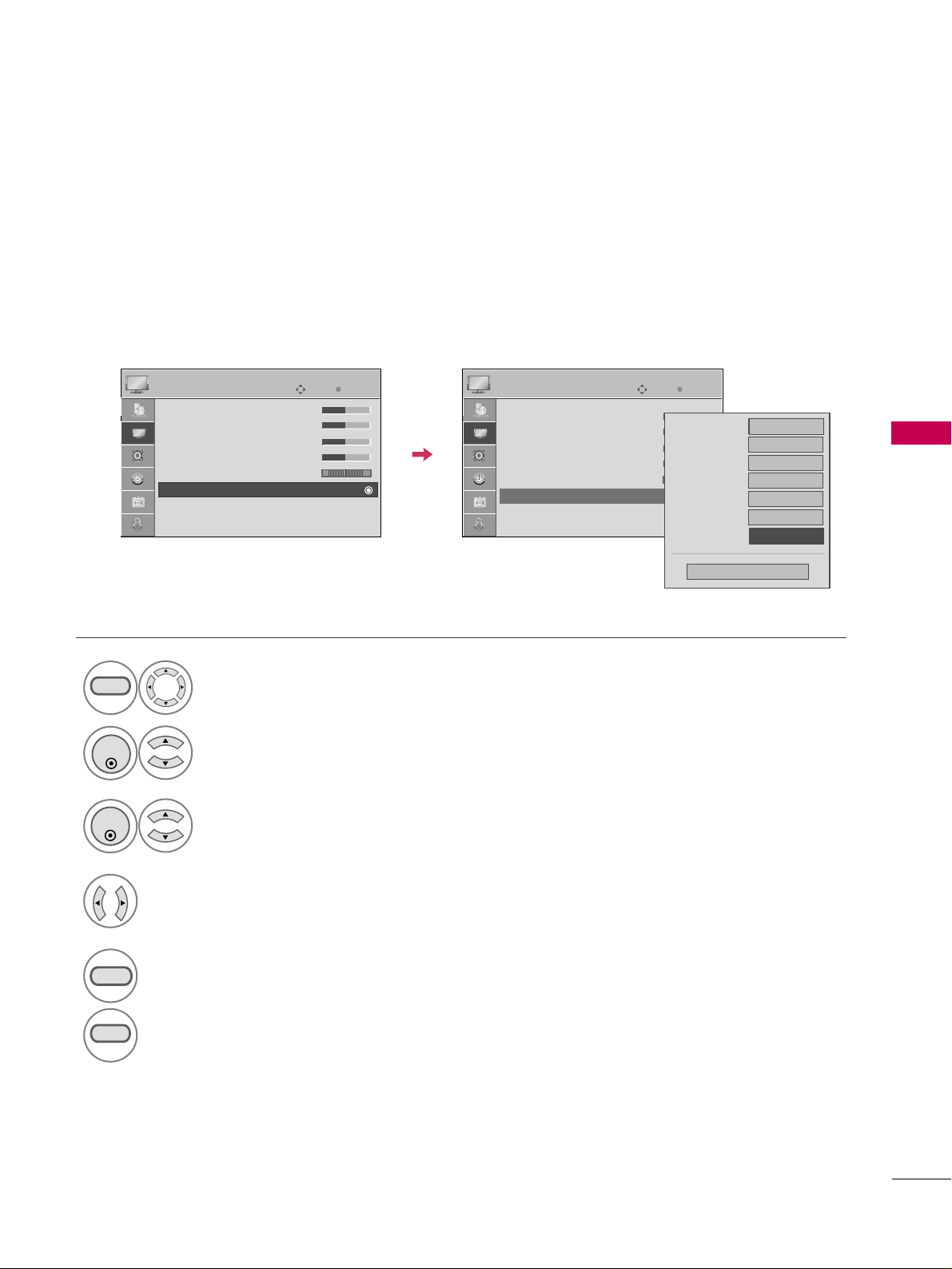
PICTURE CONTROL
57
ADVANCED CONTROL - REAL CINEMA
Set up the TV for the best picture appearance for viewing movies.
When you operate Real Cinema (3:2 Pull-Down Mode or Cinema Correction Mode), the TV will adjust 24 fps
video from movies to 30 fps video for display.
This feature operates only in TV (Analog TV/CATV, Digital DTV/CADTV), AV/AV1-2, Component 480i/1080i,
and HDMI 480i/1080i mode.
Select
PPIICCTTUURREE
.
Select
AAddvvaanncceedd CCoonnttrrooll
.
Select
RReeaall CCiinneemmaa
.
1
MENU
3
2
ENTER
ENTER
Select
OOnn
or
OOffff
.
4
5
RETURN
Return to the previous menu.
MENU
Return to TV viewing.
Enter
Move
PICTURE
E
RG
• Contrast 50
• Brightness 50
• Sharpness 50
• Color 50
• Tint 0
• Advanced Control
• Reset
Screen (RGB-PC)
Enter
Move
PICTURE
E
RG
• Contrast 50
• Brightness 50
• Sharpness 50
• Color 50
• Tint 0
• Advanced Control
• Reset
Screen (RGB-PC)
Color Temperature
FF
Medium
GG
Fresh Contrast
Off
Fresh Color
Off
Noise Reduction
Auto
Gamma
Medium
Black Level
Medium
Close
Real Cinema
Off
Medium
FF
Off
GG

PICTURE CONTROL
58
PICTURE CONTROL
PICTURE RESET
Settings of the selected picture modes return to the default factory settings.
Select
PPIICCTTUURREE
.
Select
RReesseett
.
Initialize the adjusted value.
1
MENU
3
2
ENTER
ENTER
MENU
Return to TV viewing.
Enter
Move
PICTURE
E
RG
• Contrast 50
• Brightness 50
• Sharpness 50
• Color 50
• Tint 0
• Advanced Control
• Reset
Screen (RGB-PC)
Enter
Move
PICTURE
E
RG
• Contrast 50
• Brightness 50
• Sharpness 50
• Color 50
• Tint 0
• Advanced Control
• Reset
Screen (RGB-PC)
Resetting video configuration...
ii

SOUND & LANGUAGE CONTROL
59
SOUND & LANGUAGE CONTROL
AUTO VOLUME LEVELER (AUTO VOLUME)
Auto Volume makes sure that the volume level remains consistent whether you are watching a commercial or a
regular TV program.
Select
AAUUDDIIOO
.
Select
AAuuttoo VVoolluummee
.
Select
OOnn
or
OOffff
.
1
MENU
3
2
ENTER
ENTER
4
RETURN
Return to the previous menu.
MENU
Return to TV viewing.
Enter
Move
AUDIO
Auto Volume : Off
Clear Voice : On
Balance 0
Sound Mode : Standard
•
SRS TruSurround XT:
Off
• Treble 50
• Bass 50
• Reset
Enter
Move
AUDIO
Auto Volume : Off
Clear Voice : On
Balance 0
Sound Mode : Standard
•
SRS TruSurround XT:
Off
• Treble 50
• Bass 50
• Reset
LR
LR
Off
On
E
E

SOUND & LANGUAGE CONTROL
60
SOUND & LANGUAGE CONTROL
CLEAR VOICE
By differentiating the human sound range from others, it improves the sound quality of voices.
■
If you select “
CClleeaarr VVooiiccee--OOnn
”,
SSRR SS
TTrruuSSuurrrroouunndd XXTT
feature will not work.
Select
AAUUDDIIOO
.
Select
CClleeaarr VVooiiccee
.
Select
OOnn
or
OOffff
.
1
MENU
3
2
ENTER
ENTER
4
RETURN
Return to the previous menu.
MENU
Return to TV viewing.
Enter
Move
AUDIO
Auto Volume : Off
Clear Voice : On
Balance 0
Sound Mode : Standard
•
SRS TruSurround XT:
Off
• Treble 50
• Bass 50
• Reset
Enter
Move
AUDIO
Auto Volume : Off
Clear Voice : On
Balance 0
Sound Mode : Standard
•
SRS TruSurround XT:
Off
• Treble 50
• Bass 50
• Reset
LR
LR
Off
On
E
E
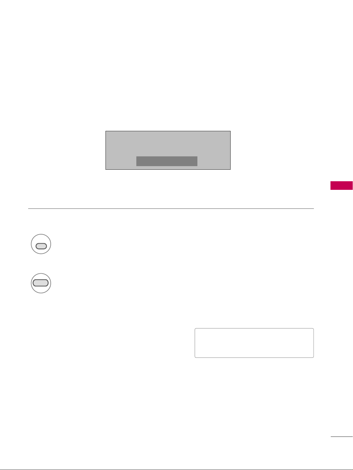
SOUND & LANGUAGE CONTROL
61
PRESET SOUND SETTINGS (SOUND MODE)
Sound Mode lets you enjoy the best sound without any special adjustment as the TV sets the appropriate
sound options based on the program content.
SSttaannddaarrdd
,
MMuussiicc
,
CCiinneemmaa
,
SSppoorrtt
, and
GGaa mmee
are preset for optimum sound quality at the factory and are
not adjustable.
1
SOUND
Press the
SSOOUUNNDD
button repeatedly to select the sound options
:
SSttaannddaarrdd
,
MMuussiicc
,
CCiinneemmaa
,
SSppoorrtt
, and
GGaammee
.
■
You can also adjust
SSoouunndd MMooddee
in
the
AAUUDDIIOO
menu.
Return to TV viewing.
2
RETURN
SSttaannddaarrdd
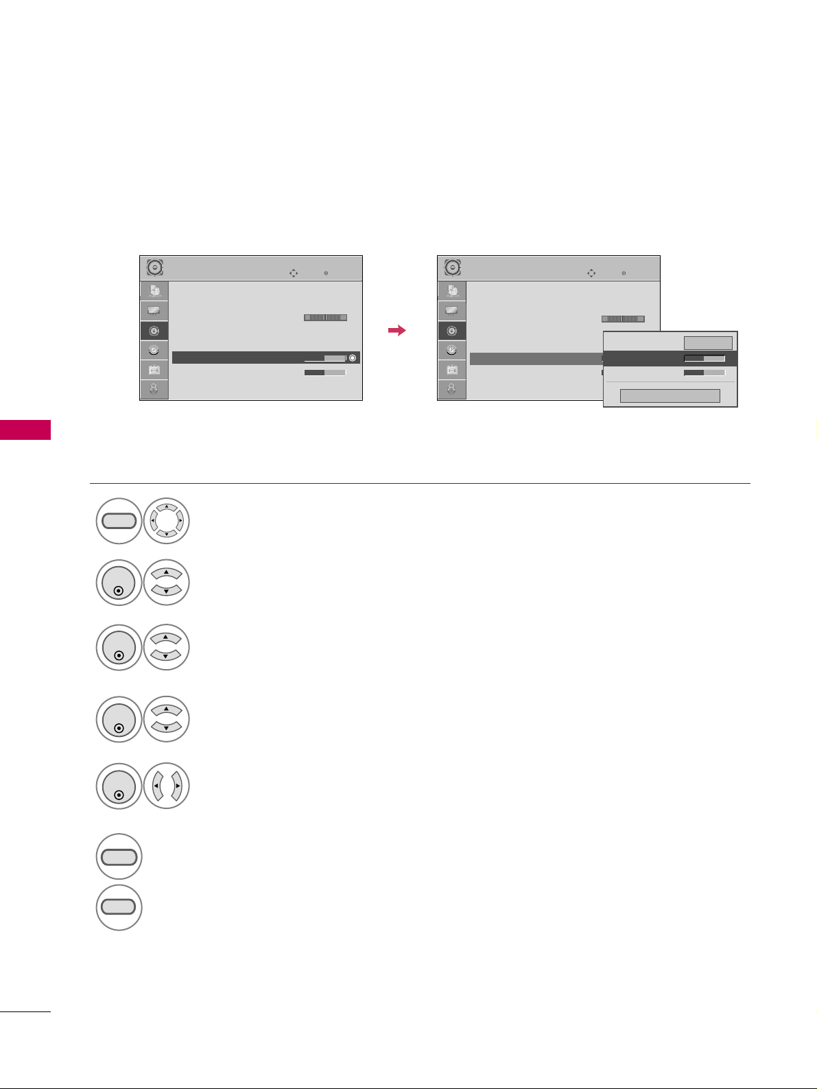
SOUND & LANGUAGE CONTROL
62
SOUND & LANGUAGE CONTROL
SOUND SETTING ADJUSTMENT - USER MODE
Adjust the sound to suit your taste and room situations.
Select
AAUUDDIIOO
.
Select
SSoouunndd MMooddee
.
Select
TTrreebbllee
or
BBaassss
.
1
MENU
4
2
ENTER
Select
SSttaannddaarrdd
,
MMuussiicc
,
CCiinneemmaa
,
SSppoorrtt
, or
GGaammee
.
3
ENTER
ENTER
Make appropriate adjustments.
5
ENTER
6
RETURN
Return to the previous menu.
MENU
Return to TV viewing.
Enter
Move
AUDIO
Auto Volume : Off
Clear Voice : On
Balance 0
Sound Mode : Standard
•
SRS TruSurround XT:
Off
• Treble 50
• Bass 50
• Reset
Enter
Move
AUDIO
Auto Volume : Off
Clear Voice : On
Balance 0
Sound Mode : Standard
•
SRS TruSurround XT:
Off
• Treble 50
• Bass 50
• Reset
LR
LR
Close
EE
EE
Treble 50
Bass 50
SRS TruSurround XT
Off
E
E
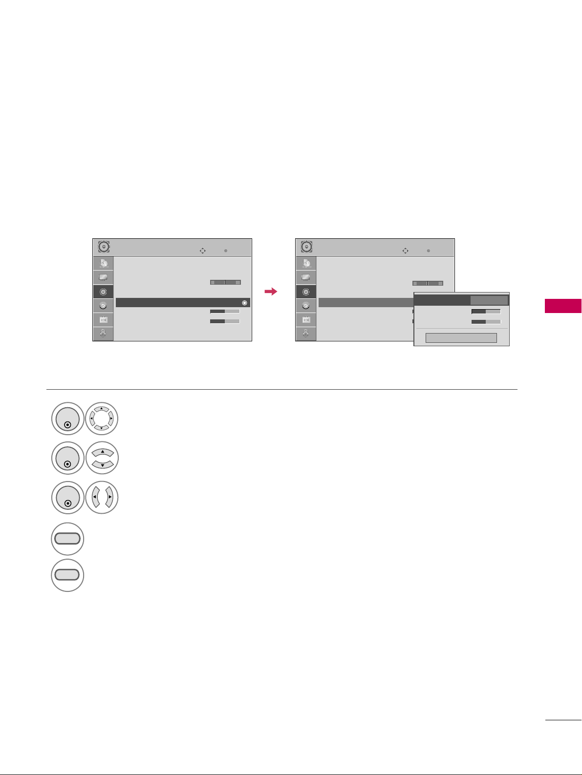
SOUND & LANGUAGE CONTROL
63
Enter
Move
AUDIO
LR
SRS TRUSURROUND XT
Select
AAUUDDIIOO
.
Select
SSRRSS TTrruuSSuurrrroouunndd XXTT
.
Select
OOnn
or
OOffff
.
1
ENTER
3
2
ENTER
ENTER
4
RETURN
Return to the previous menu.
MENU
Return to TV viewing.
Enter
Move
AUDIO
Auto Volume : Off
Clear Voice : On
Balance 0
Sound Mode : Standard
•
SRS TruSurround XT:
Off
• Treble 50
• Bass 50
• Reset
LR
E
E
Auto Volume : Off
Clear Voice : On
Balance 0
Sound Mode : Standard
•
SRS TruSurround XT:
Off
• Treble 50
• Bass 50
• Reset
Treble 50
Bass 50
Close
SRS TruSurround XT
Off
FF
Off
GG
Takes advantage of any multi-channel format without needing to add extra speakers or equipment. Dialog
clarity, bass enrichment, and the addition of stereo audio enhancement produces an immersive sound experi-
ence from standard stereo material.
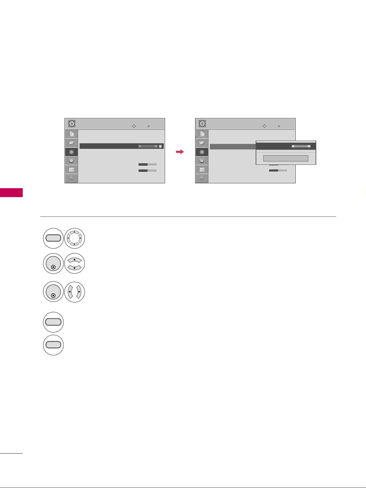
SOUND & LANGUAGE CONTROL
64
SOUND & LANGUAGE CONTROL
BALANCE
Select
AAUUDDIIOO
.
Select
BBaallaannccee
.
Make appropriate adjustments.
1
MENU
3
2
ENTER
ENTER
Adjust the left/right sound of speaker to suit your taste and room situations.
4
RETURN
Return to the previous menu.
MENU
Return to TV viewing.
Enter
Move
AUDIO
Auto Volume : Off
Clear Voice : On
Balance 0
Sound Mode : Standard
•
SRS TruSurround XT:
Off
• Treble 50
• Bass 50
• Reset
Enter
Move
AUDIO
Auto Volume : Off
Clear Voice : On
Balance 0
Sound Mode : Standard
•
SRS TruSurround XT:
Off
• Treble 50
• Bass 50
• Reset
LR
LR
Close
EE
EE
Balance 0
LR
E
E
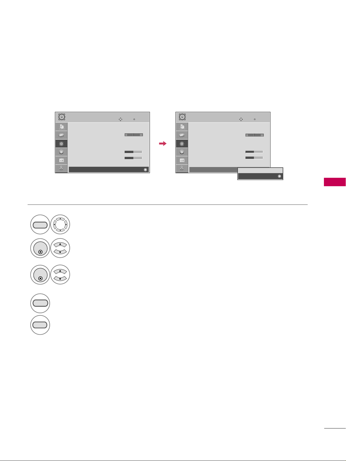
SOUND & LANGUAGE CONTROL
65
TV SPEAKERS ON/OFF SETUP
Turn the TV speakers off if using external audio equipment.
Select
AAUUDDIIOO
.
Select
TTVV SSppeeaakkeerr
.
Select
OOnn
or
OOffff
.
1
MENU
3
2
ENTER
ENTER
4
RETURN
Return to the previous menu.
MENU
Return to TV viewing.
Enter
Move
AUDIO
Clear Voice : On
Balance 0
Sound Mode : Standard
•
SRS TruSurround XT:
Off
• Treble 50
• Bass 50
• Reset
TV Speaker : On
Enter
Move
AUDIO
Clear Voice : On
Balance 0
Sound Mode : Standard
•
SRS TruSurround XT:
Off
• Treble 50
• Bass 50
• Reset
TV Speaker : On
LR
LR
EE
Off
On
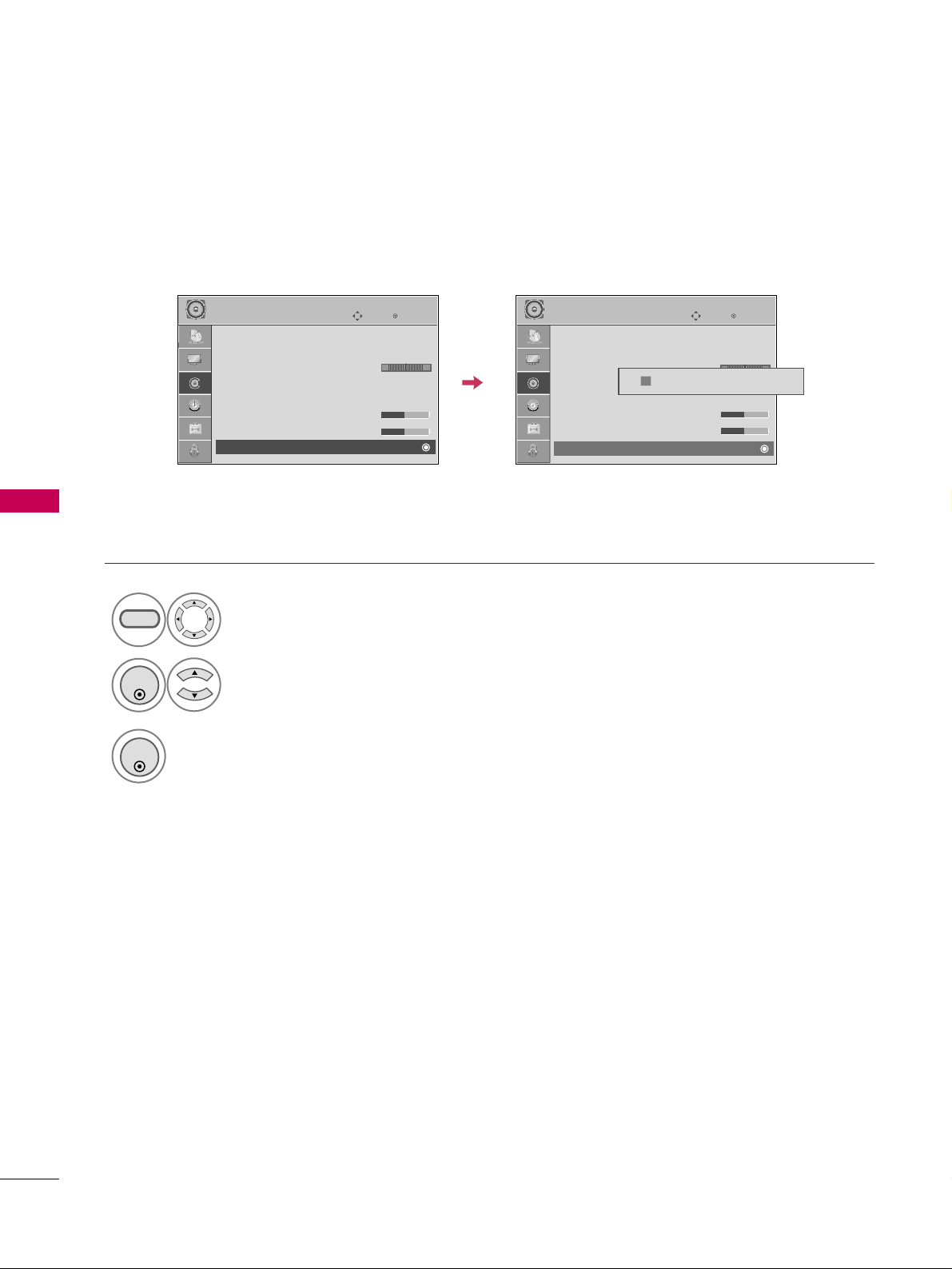
SOUND & LANGUAGE CONTROL
66
SOUND & LANGUAGE CONTROL
AUDIO RESET
Settings of the selected Sound Mode return to the default factory settings.
Select
AAUUDDIIOO
.
Select
RReesseett
.
1
MENU
2
ENTER
Initialize the adjusted value.
3
ENTER
Enter
Move
AUDIO
Auto Volume : Off
Clear Voice : On
Balance 0
Sound Mode : Standard
•
SRS TruSurround XT:
Off
• Treble 50
• Bass 50
• Reset
Enter
Move
AUDIO
Auto Volume : Off
Clear Voice : On
Balance 0
Sound Mode : Standard
•
SRS TruSurround XT:
Off
• Treble 50
• Bass 50
• Reset
LR
LR
E E
Resetting audio configuration...
ii
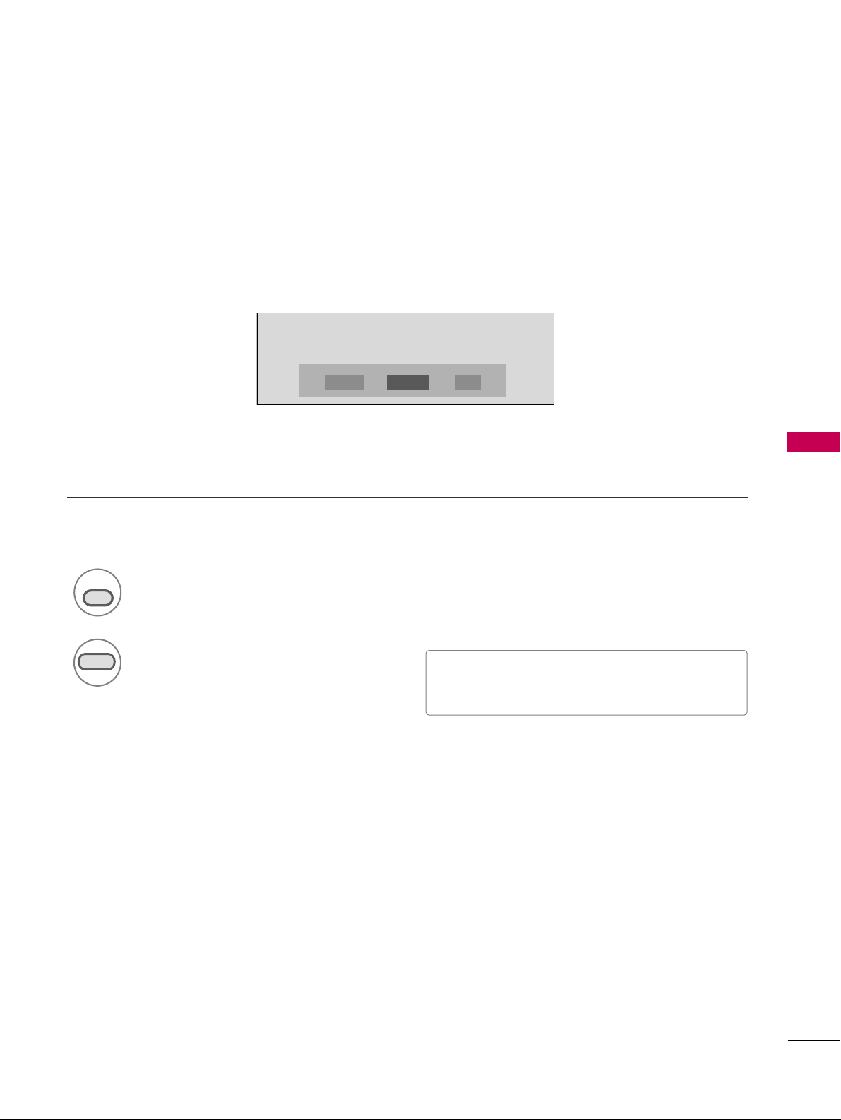
SOUND & LANGUAGE CONTROL
67
Each time you press the
SSAAPP
button,
MMoonnoo
,
SStteerreeoo
, or
SSAAPP
appear in turn.
Return to TV viewing.
1
SAP
2
STEREO/SAP BROADCAST SETUP
For Analog only: This TV can receive MTS stereo programs and any SAP (Secondary Audio Program) that accom-
panies the stereo program if the station transmits an additional sound signal. Mono sound is automatically used
if the broadcast is only in Mono.
■
If other languages available on the digital signal,
select them with the
SSAAPP
button.
RETURN
MONO SAPSTEREO
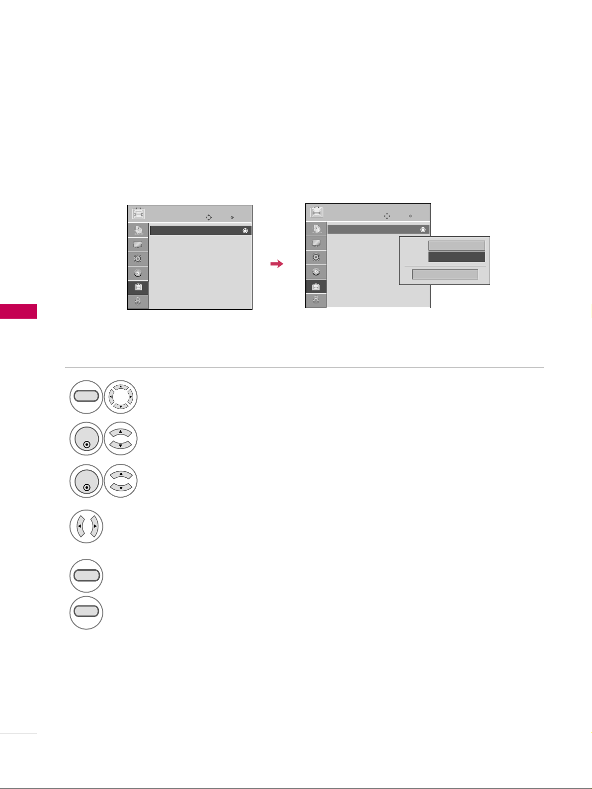
SOUND & LANGUAGE CONTROL
68
SOUND & LANGUAGE CONTROL
Enter
Move
OPTION
Enter
Move
OPTION
AUDIO LANGUAGE
Other languages may be available if a digital signal is provided by the broadcasting station.
This feature operates only in DTV/CADTV mode.
Select
OOPPTTIIOONN
.
Select
LLaanngguuaaggee
.
Select
AAuuddiioo
.
1
MENU
3
2
ENTER
ENTER
Select your desired language:
EEnngglliisshh
,
SSppaanniisshh
, or
FFrreenncchh
4
5
RETURN
Return to the previous menu.
MENU
Return to TV viewing.
Language : English
Caption : Off
Menu
English
Audio
FF
English
GG
Close
Language : English
Caption : Off
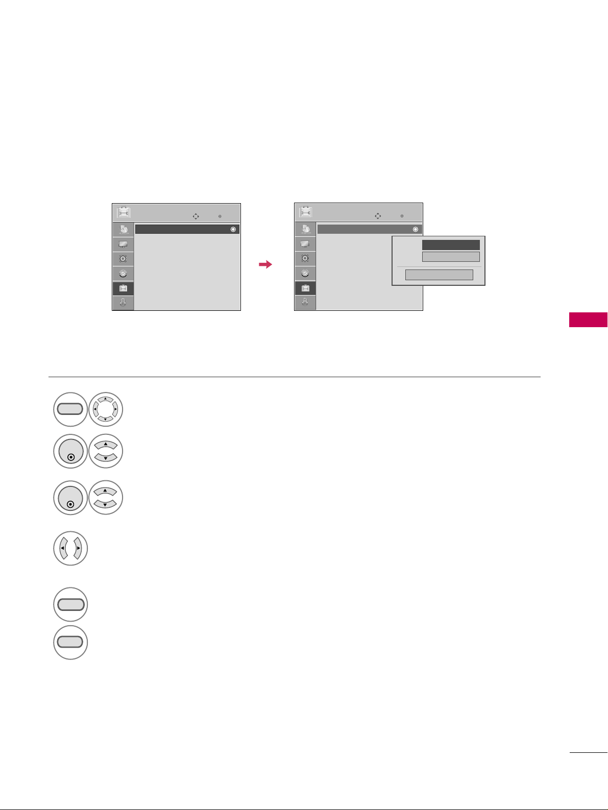
SOUND & LANGUAGE CONTROL
69
Enter
Move
OPTION
Enter
Move
OPTION
ON-SCREEN MENUS LANGUAGE SELECTION
The menus can be shown on the screen in the selected language.
Select
OOPPTTIIOONN
.
Select
LLaanngguuaaggee
.
Select
MMeennuu
.
1
MENU
3
2
ENTER
ENTER
Select your desired language.
From this point on, the on-screen menus
will be shown in the selected language.
4
5
RETURN
Return to the previous menu.
MENU
Return to TV viewing.
Language : English
Caption : Off
Language : English
Caption : Off
Menu
FF
English
GG
Audio
English
Close

SOUND & LANGUAGE CONTROL
70
SOUND & LANGUAGE CONTROL
CAPTION MODE
Caption must be provided to help people with hearing loss watch TV.
This feature operates only in TV, AV/AV1-2 mode.
Select Caption
OOnn
or
OOffff
.
1
cc
■
When selecting
OOffff
, Sub-menus for
Analog, DTV, and Digital Option
become disabled.
Caption must be provided to help people with hearing loss watch TV. Select a caption mode for displaying cap-
tioning information if provided on a program. Analog caption displays information at any position on the screen
and is usually the program's dialog. Caption/Text, if provided by the broadcaster, would be available for both
digital and analog channels on the Antenna/Cable.
Analog Broadcasting System Captions
Select
OOPPTTIIOONN
.
Select
CCaappttiioonn
.
Select
OOnn
.
1
MENU
3
2
ENTER
ENTER
Select
CCCC11
-
44
or
TTeexxtt11
-
44
.
4
■
CCAAPPTTIIOONN
The term for the words that scroll
across the bottom of the TV screen;
usually the audio portion of the pro-
gram provided for the hearing impaired.
■
TTEEXXTT
The term for the words that appear in a
large black frame and almost cover the
entire screen; usually messages provid-
ed by the broadcaster.
5
RETURN
Return to the previous menu.
MENU
Return to TV viewing.
Enter
Move
OPTION
Mode
CC1
Close
Digital Option
FF
On
GG
Language : English
Caption : CC1
Enter
Move
OPTION
Language : English
Caption : Off
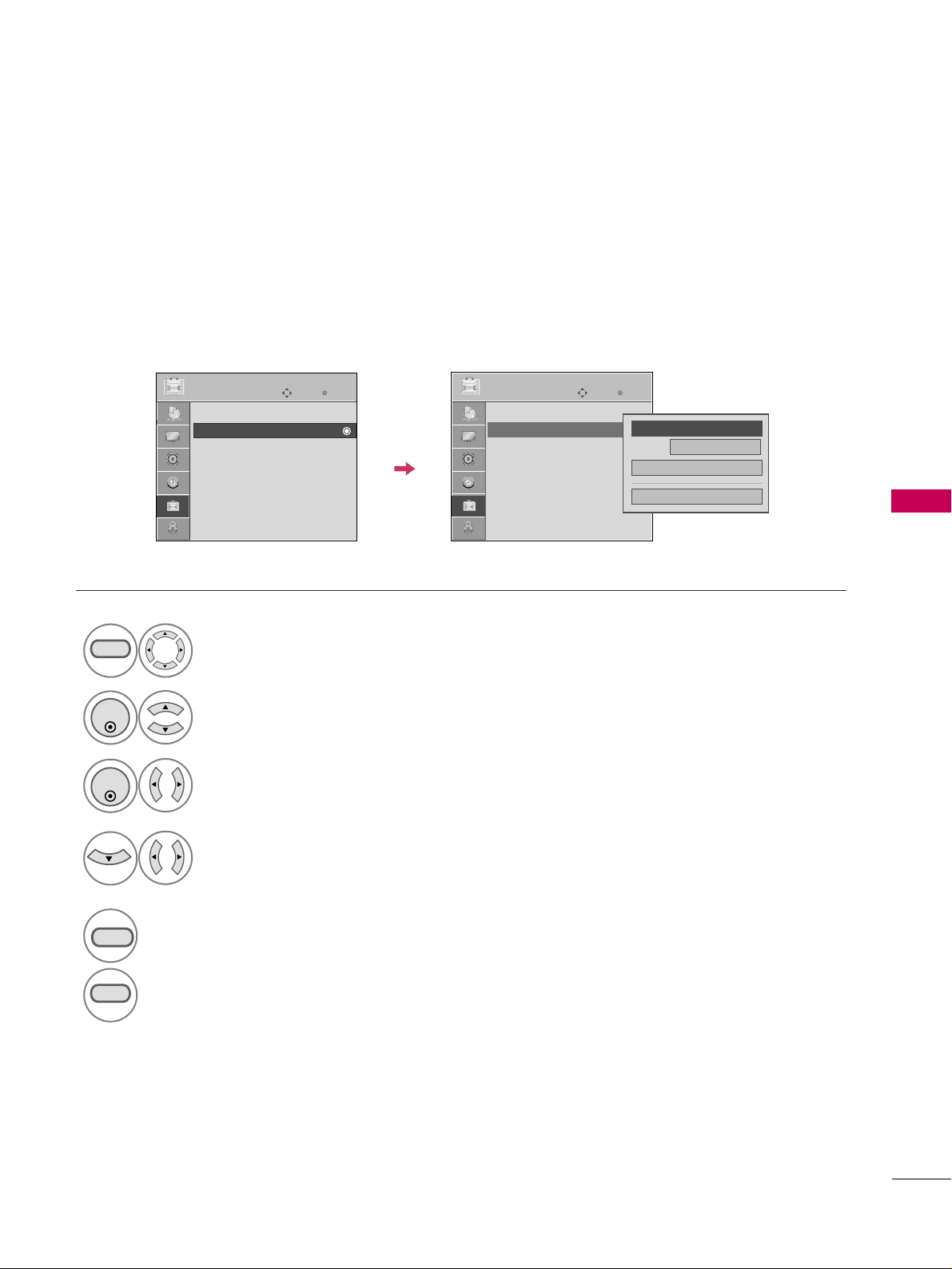
SOUND & LANGUAGE CONTROL
71
Digital Broadcasting System Captions
Choose the language you want the DTV/CADTV Captions to appear in.
Other Languages can be chosen for digital sources only if they are included on the program.
This function in only available when Caption Mode is set On.
Enter
Move
OPTION
Select
OOPPTTIIOONN
.
Select
CCaappttiioonn
.
Select
OOnn
.
1
MENU
3
2
ENTER
ENTER
Select
CCCC11
-
44
,
TTeexxtt11
-
44
, or
SSeerrvviiccee11
-
66
.
4
5
RETURN
Return to the previous menu.
MENU
Return to TV viewing.
Enter
Move
OPTION
Language : English
Caption : CC1
Language : English
Caption : Off
Mode
CC1
Close
Digital Option
FF
On
GG
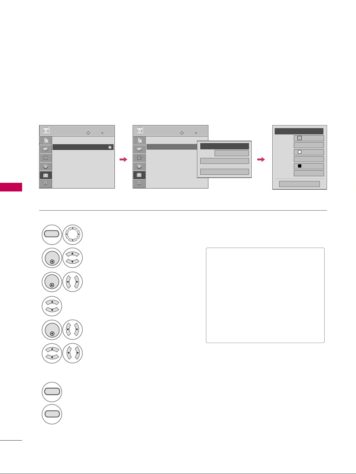
SOUND & LANGUAGE CONTROL
72
SOUND & LANGUAGE CONTROL
Enter
Move
OPTION
Caption Option
Customize the DTV/CADTV captions that appear on your screen.
This function in only available when Caption Mode is set On.
Select
OOPPTTIIOONN
.
Select
CCaappttiioonn
.
Select
OOnn
.
1
MENU
3
2
ENTER
ENTER
Select
CCuussttoomm
.
5
ENTER
Customize the
SSttyyllee
,
FFoonntt
, etc., to your
preference. A preview icon is provided at
the bottom of the screen, use it to see the
caption language.
6
Select
DDiiggiittaall OOppttiioonn
.
4
■
SSiizzee
: Set the word size.
■
FFoonntt
: Select a typeface for the text.
■
TTeexxtt CCoolloorr
: Choose a color for the
text.
■
TTeexxtt OOppaacciittyy
: Specify the opacity
for the text color.
■
BBgg ((BBaacckkggrroouunndd)) CCoolloorr
: Select a
background color.
■
BBgg ((BBaacckkggrroouunndd)) OOppaacciittyy
: Select
the opacity for the background color.
7
RETURN
Return to the previous menu.
MENU
Return to TV viewing.
Size
A Standard
Font
Font 1
Text Color
White
Text Opacity
Solid
Bg Color
Black
Bg Opacity
Solid
Close
FF
Custom
GG
Mode
CC1
Close
Digital Option
FF
On
GG
Enter
Move
OPTION
Language : English
Caption : Off
Language : English
Caption : CC1

TIME SETTING
73
CLOCK SETTING
TIME SETTING
Auto Clock Setup
The time is set automatically from a digital channel signal.
The digital channel signal includes information for the current time provided by the broadcasting station.
Set the clock manually if the current time is set incorrectly by the auto clock function.
Select
TTIIMMEE
.
Select
CClloocckk
.
Select
AAuuttoo
.
1
MENU
3
2
ENTER
ENTER
Select your viewing area time zone.
:
EEaasstteerrnn
,
CCeennttrraall
,
MMoouunnttaaiinn
,
PPaacciiffiicc
,
AAllaasskkaa
, or
HHaawwaaiiii
.
4
Select
AAuuttoo
,
OOnn
, or
OOffff
(depending on
whether or not your viewing area observes
Daylight Saving time).
5
6
RETURN
Return to the previous menu.
MENU
Return to TV viewing.
Enter
Move
TIME
Clock :
Feb/21/2008/ 2:10 AM
Off Time : Off
On Time : Off
Sleep Timer : Off
Auto Sleep : Off
Enter
Move
TIME
Clock :
Feb/21/2008/ 2:10 AM
Off Time : Off
On Time : Off
Sleep Timer : Off
Auto Sleep : Off
Year
Month
2
Date
21
Hour
2 AM
2008
Minute
10
Time Zone
Eastern
Daylight
Saving
Auto
Close
FF
Auto
GG
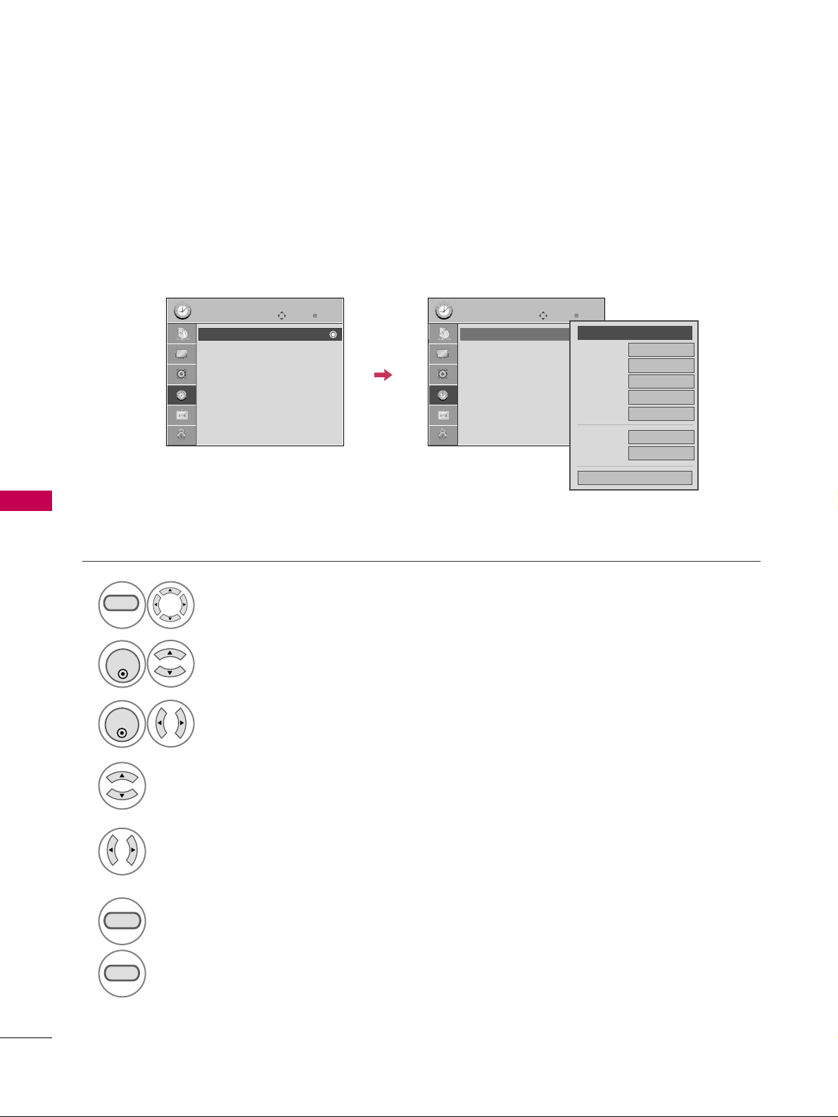
TIME SETTING
74
TIME SETTINGTIME SETTING
Manual Clock Setup
If the current time setting is wrong, set the clock manually.
Select
TTIIMMEE
.
Select
CClloocckk
.
Select
MMaannuuaall
.
1
MENU
3
2
ENTER
ENTER
Select the Year, Month, Date, Hour, or Minute option.
4
Set the Year, Month, Date, Hour, or Minute option.
5
6
RETURN
Return to the previous menu.
MENU
Return to TV viewing.
Enter
Move
TIME
Clock :
Feb/21/2008/ 2:10 AM
Off Time : Off
On Time : Off
Sleep Timer : Off
Auto Sleep : Off
Enter
Move
TIME
Clock :
Feb/21/2008/ 2:10 AM
Off Time : Off
On Time : Off
Sleep Timer : Off
Auto Sleep : Off
Year
Month
2
Date
21
Hour
2 AM
2008
Minute
10
Time Zone
Eastern
Daylight
Saving
Auto
Close
FF
Manual
GG
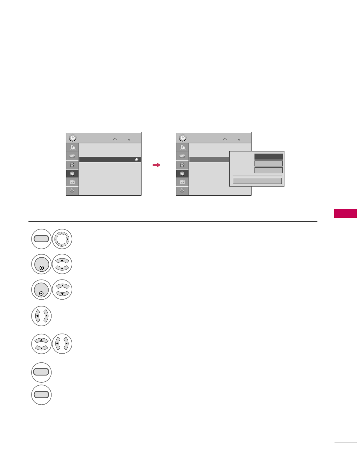
TIME SETTING
75
AUTO ON/OFF TIME SETTING
This function operates only if the current time has been set.
The
OOffff TTiimmee
function overrides the
OOnn TTiimmee
function if they are both set to the same time.
The TV must be in standby mode for the
OOnn TTiimmee
to work.
Select
TTIIMMEE
.
Select
OOffff TTiimmee
or
OOnn TTiimmee
.
Select
RReeppeeaatt
.
1
MENU
3
2
ENTER
ENTER
Select
OOffff
,
OOnnccee
,
EEvveerryyddaayy
,
MMoo nn
~
FF rrii
,
MMoo nn
~
SSaa tt
,
WWeeeekkeenndd
, or
SSuunnddaayy
.
4
Select and set
HHoouurr
or
MMiinnuuttee
.
5
6
RETURN
Return to the previous menu.
MENU
Return to TV viewing.
Enter
Move
TIME
Clock :
Feb/21/2008/ 2:10 AM
Off Time : Off
On Time : Off
Sleep Timer : Off
Auto Sleep : Off
Enter
Move
TIME
Clock :
Feb/21/2008/ 2:10 AM
Off Time : Off
On Time : 6:30 AM (Once)
Sleep Timer : Off
Auto Sleep : Off
Repeat
FF
Once
GG
Hour
6 AM
Minute
30
Close
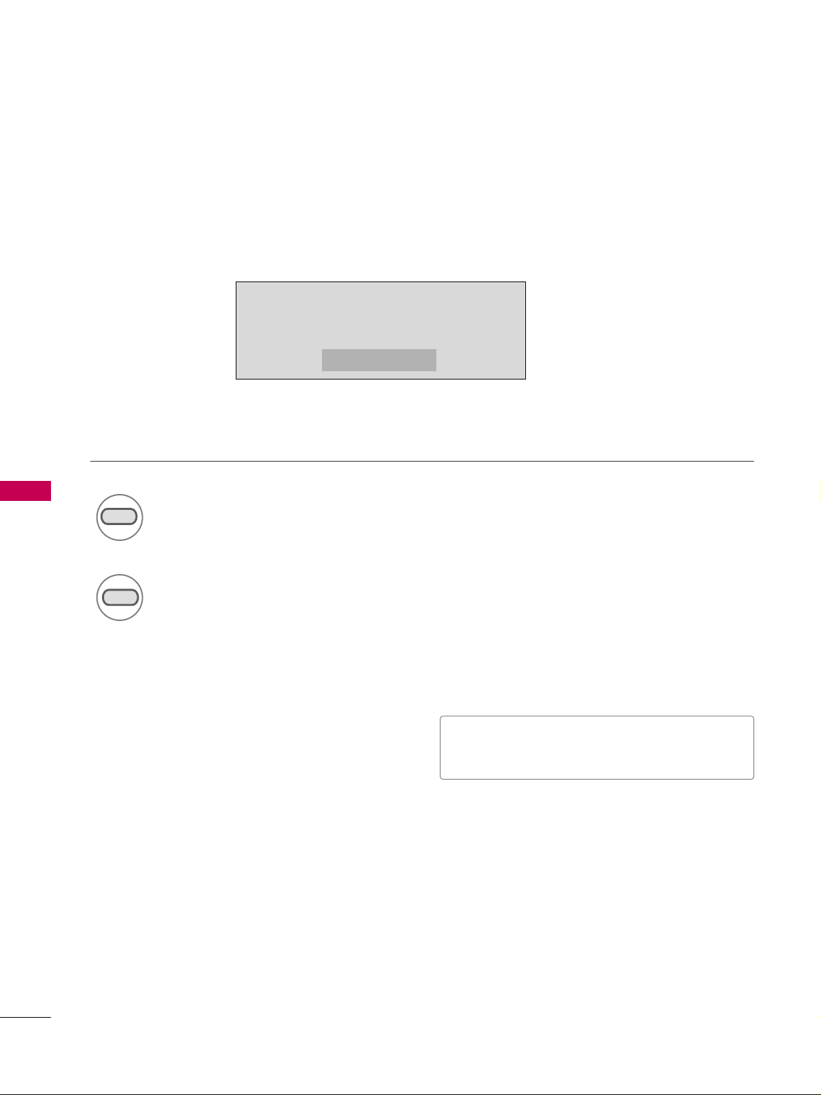
TIME SETTING
76
TIME SETTINGTIME SETTING
SLEEP TIMER SETTING
The Sleep Time turns the TV off at the preset time.
Note that this setting is cleared when the TV is turned off.
Press the
TTIIMMEERR
button repeatedly to select the number of minutes.
Sleep timer options: Off, 10, 20, 30, 60, 90, 120, 180, and 240 minutes.
1
TIMER
2
RETURN
■
You can also adjust
SSlleeeepp TTiimmeerr
in the
TTIIMMEE
menu.
10min
Return to TV viewing.
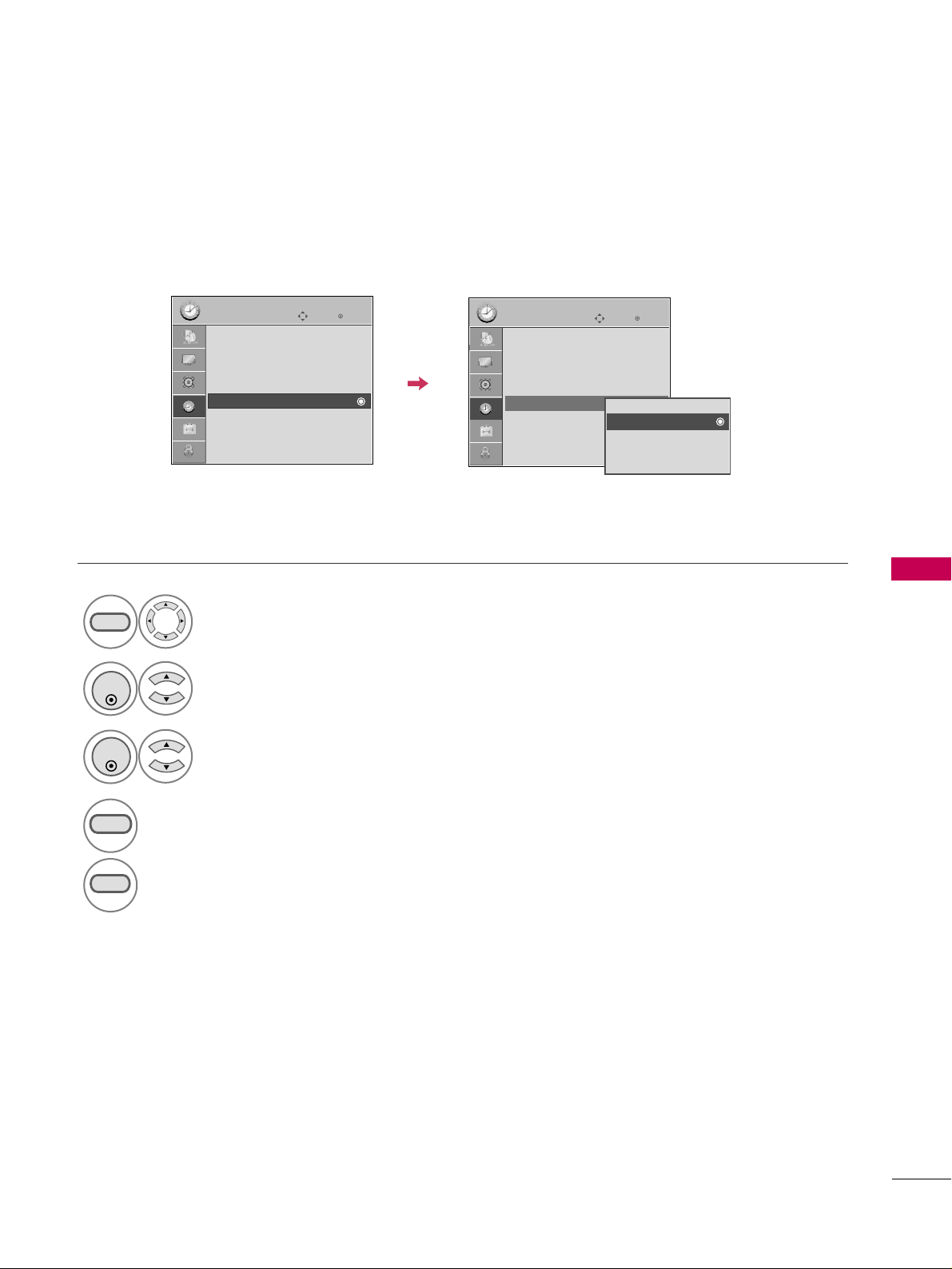
TIME SETTING
77
AUTO SHUT-OFF SETTING
TV will be automatically turned off, in case of no signal for 10 minutes.
Select
TTIIMMEE
.
Select
AAuuttoo SSlleeeepp
.
Select
OOnn
or
OOffff
.
1
MENU
3
2
ENTER
ENTER
4
RETURN
Return to the previous menu.
MENU
Return to TV viewing.
Enter
Move
TIME
Clock :
Feb/21/2008/ 2:10 AM
Off Time : Off
On Time : Off
Sleep Timer : Off
Auto Sleep : Off
Enter
Move
TIME
Clock :
Feb/21/2008/ 2:10 AM
Off Time : Off
On Time : Off
Sleep Timer : Off
Auto Sleep : Off
Off
On
TV will be automatically turned off,
in case of No Signal for 10 minutes.
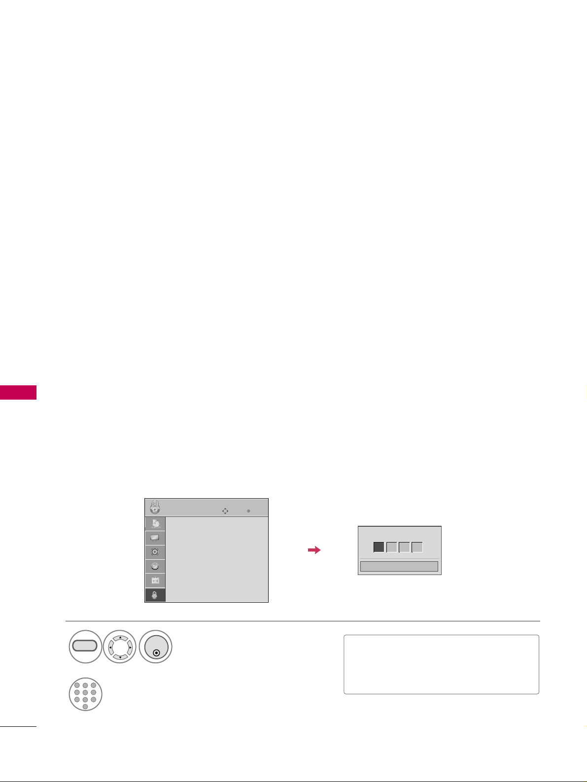
PARENTAL CONTROL / RATINGS
78
PARENTAL CONTROL / RATINGS
Parental Control can be used to block specific channels, ratings and other viewing sources.
The Parental Control Function (V-Chip) is used to block program viewing based on the ratings sent by the broad-
casting station. The default setting is to allow all programs to be viewed. Viewing can be blocked by choosing the
type of the program and the categories. It is also possible to block all program viewing for a time period. To use
this function, the following must be done :
1. Set ratings and categories to be blocked.
2. Specify a password
3. Enable the lock
V-Chip rating and categories
Rating guidelines are provided by broadcasting stations. Most television programs and television movies can be
blocked by TV Rating and/or Individual Categories. Movies that have been shown at the theaters or direct-to-
video movies use the Movie Rating System
(
MPAA
)
only.
Ratings for Television programs including made-for-TV movies :
■
TV-G
(
General audience
)
■
TV-PG
(
Parental guidance suggested
)
■
TV-14
(
Parents strongly cautioned
)
■
TV-MA
(
Mature audience only
)
■
TV-Y
(
All children
)
■
TV-Y7
(
Children 7 years older
)
Set up blocking schemes to block specific channels, ratings, and external viewing sources.
A password is required to gain access to this menu.
Setting up Your Password
Close
Enter Password
* * * *
Select
LLOOCCKK
.
1
MENU
ENTER
Input the password.
2
1
456
78
0
9
23
■
Enter the password as requested.
■
The TV is set up with the initial pass-
word “0-0-0-0”.
SET PASSWORD & LOCK SYSTEM
Enter
Move
LOCK
Lock System : Off
Set Password
Block Channel
Movie Rating
TV Rating-Children
TV Rating-General
Downloadable Rating
Input Block
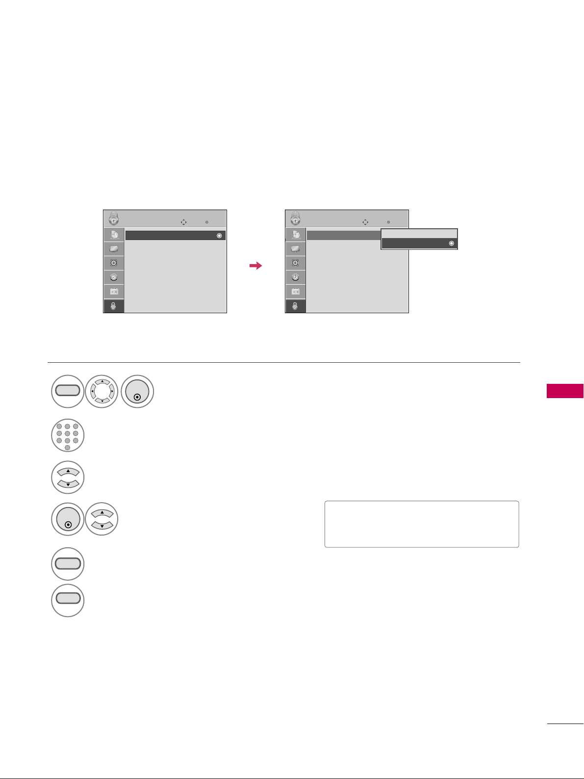
PARENTAL CONTROL / RATINGS
79
Enables or disables the blocking scheme you set up previously.
Lock System
Select
LLoocckk SSyysstteemm
.
Select
OOnn
or
OOffff
.
4
3
ENTER
■
When you select
OO nn
, the Lock System
is enable.
Select
LLOOCCKK
.
1
MENU
ENTER
Input the password.
2
1
456
78
0
9
23
5
RETURN
Return to the previous menu.
MENU
Return to TV viewing.
Enter
Move
LOCK
Lock System : Off
Set Password
Block Channel
Movie Rating
TV Rating-Children
TV Rating-General
Downloadable Rating
Input Block
Enter
Move
LOCK
Lock System : On
Set Password
Block Channel
Movie Rating
TV Rating-Children
TV Rating-General
Downloadable Rating
Input Block
Off
On
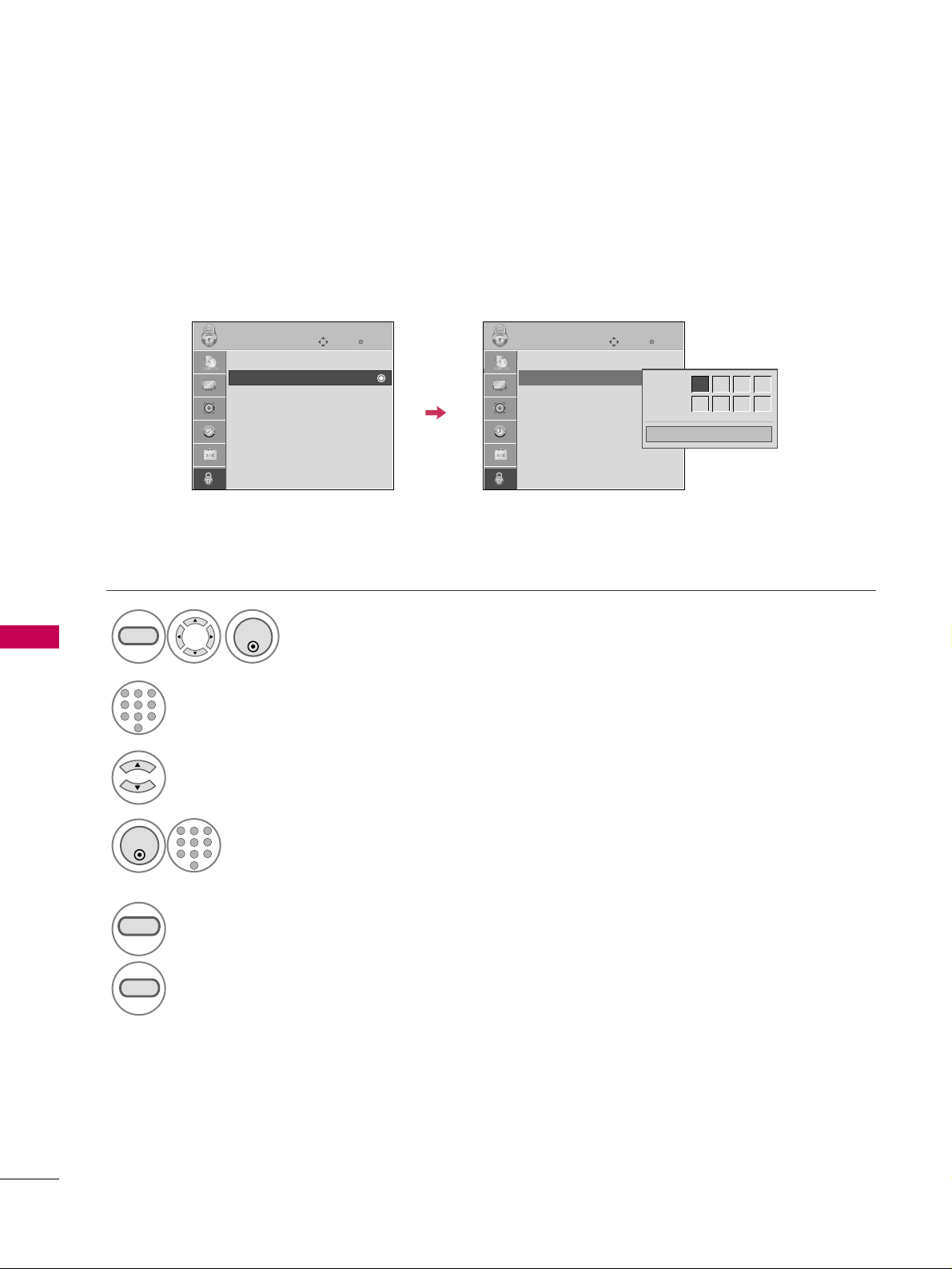
PARENTAL CONTROL / RATINGS
80
PARENTAL CONTROL /RATINGS
Change the password by inputting a new password twice.
Set Password
Select
SSeett ppaasssswwoorrdd
.
Choose any 4 digits for your new password.
As soon as the 4 digits are entered, re-enter
the same 4 digits on the
CCoonnffiirrmm
.
4
3
ENTER
1
456
78
0
9
23
Select
LLOOCCKK
.
1
MENU
ENTER
Input the password.
2
1
456
78
0
9
23
5
RETURN
Return to the previous menu.
MENU
Return to TV viewing.
Enter
Move
LOCK
Lock System : Off
Set Password
Block Channel
Movie Rating
TV Rating-Children
TV Rating-General
Downloadable Rating
Input Block
Enter
Move
LOCK
Lock System : Off
Set Password
Block Channel
Movie Rating
TV Rating-Children
TV Rating-General
Downloadable Rating
Input Block
Close
New
* * * *
Confirm
* * * *
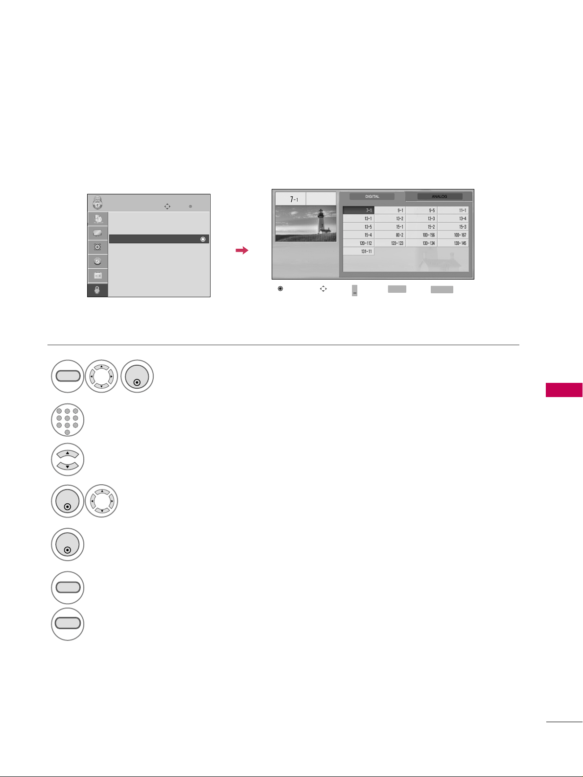
PARENTAL CONTROL / RATINGS
81
CHANNEL BLOCKING
Select
BBlloocckk CChhaannnneell
.
Select a channel to block or unblock.
4
3
ENTER
Block or unblock a channel.
5
ENTER
Blocks any channels that you do not want to watch or that you do not want your children to watch.
Select
LLOOCCKK
.
1
MENU
ENTER
Input the password.
2
1
456
78
0
9
23
6
MENU
Return to the previous menu.
RETURN
Return to TV viewing.
Block/Unblock
Move Page
CH
Move
Previous
RETURN
EXIT
MENU
Enter
Move
LOCK
Lock System : Off
Set Password
Block Channel
Movie Rating
TV Rating-Children
TV Rating-General
Downloadable Rating
Input Block
+
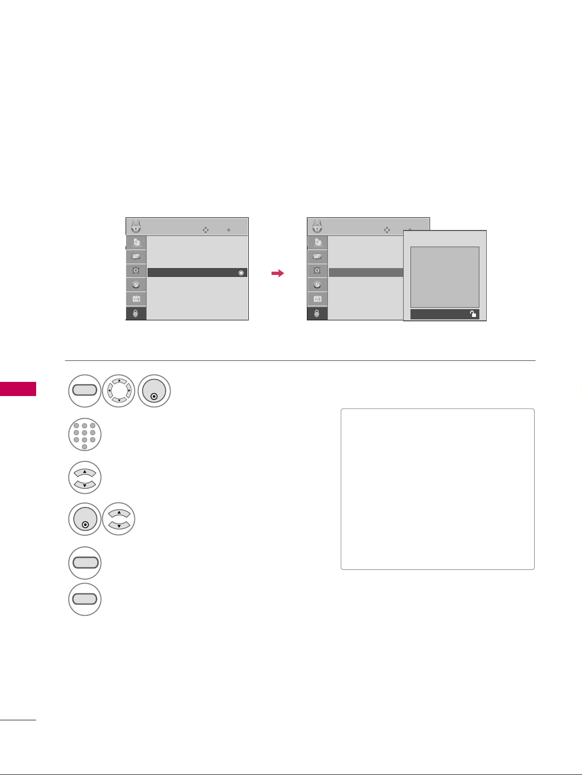
PARENTAL CONTROL / RATINGS
82
PARENTAL CONTROL /RATINGSPARENTAL CONTROL /RATINGS
MOVIE & TV RATING
Movie Rating (MPAA)
Blocks movies according to the movie ratings limits specified, so children cannot view certain movies. You can
set the ratings limit by blocking out all the movies with the ratings above a specified level. Keep in mind that
the movie ratings limit only applies to movies shown on TV, not TV programs, such as soap operas.
Select
MMoovviiee RRaattiinngg
.
Select
GG
,
PPGG
,
PPGG--1133
,
RR
,
NNCC--1177
,
XX
, or
BBlloocckkiinngg OOffff
.
4
3
ENTER
■
G (General audience)
■
PG (Parental guidance suggested)
■
PG-13 (Parents strongly cautioned)
■
R (Restricted)
■
NC-17 (No one 17 and under admitted)
■
X (Adult only)
■
Blocking Off (Permits all programs)
GG
If you set PG-13: G and PG movies will
be available, PG-13, R, NC-17 and X will
be blocked.
Select
LLOOCCKK
.
1
MENU
ENTER
Input the password.
2
1
456
78
0
9
23
5
RETURN
Return to the previous menu.
MENU
Return to TV viewing.
Enter
Move
LOCK
Lock System : Off
Set Password
Block Channel
Movie Rating
TV Rating-Children
TV Rating-General
Downloadable Rating
Input Block
Enter
Move
LOCK
Lock System : Off
Set Password
Block Channel
Movie Rating
TV Rating-Children
TV Rating-General
Downloadable Rating
Input Block
G
PG
PG-13
R
NC-17
X
Blocking Off
Blocking off : Permits all
programs
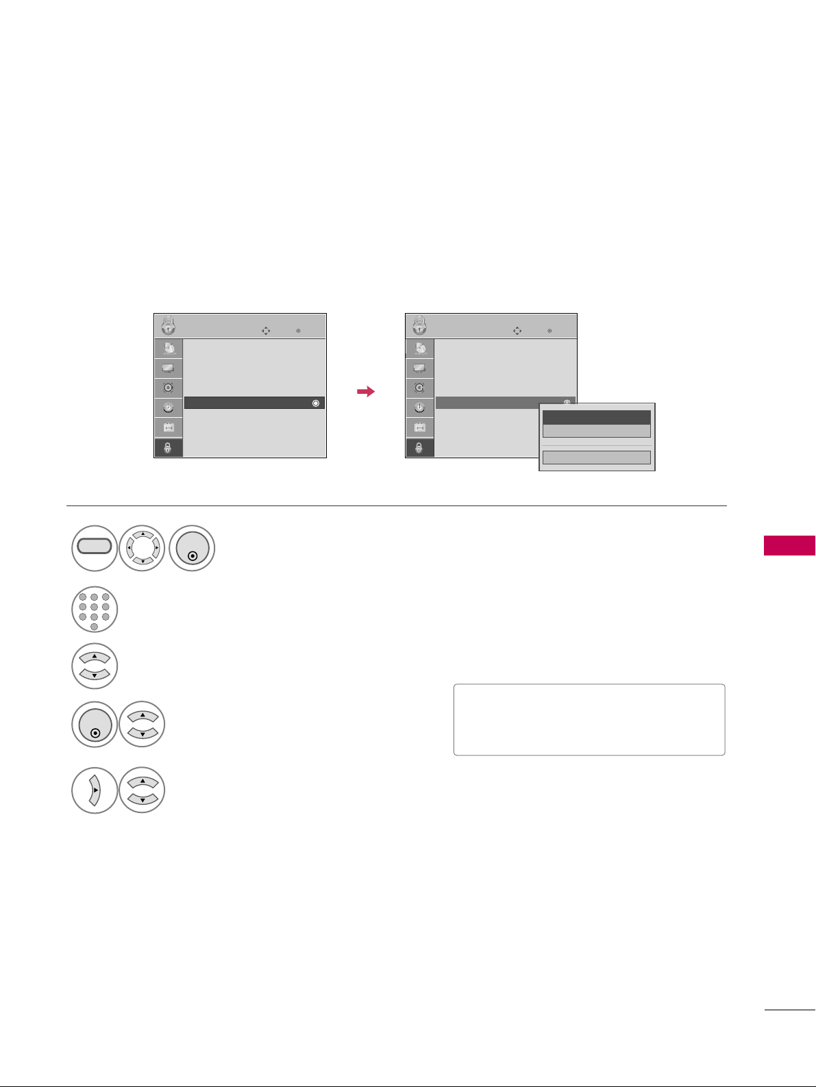
PARENTAL CONTROL / RATINGS
83
Select
TTVV RRaattiinngg--CChhiillddrreenn
.
Select
AAggee
or
FFaannttaassyy VViioolleennccee
.
4
3
ENTER
Select block options.
5
■
Age (applies to TV-Y, TV-Y7)
■
Fantasy Violence (applies to TV-Y7)
TV Rating Children
Prevents children from watching certain children's TV programs, according to the ratings limit set. The children
rating does not apply to other TV programs. Unless you block certain TV programs intended for mature audi-
ences in the TV Rating - sub menu, your children can view those programs.
Select
LLOOCCKK
.
1
MENU
ENTER
Input the password.
2
1
456
78
0
9
23
Enter
Move
LOCK
Lock System : Off
Set Password
Block Channel
Movie Rating
TV Rating-Children
TV Rating-General
Downloadable Rating
Input Block
Enter
Move
LOCK
Lock System : Off
Set Password
Block Channel
Movie Rating
TV Rating-Children
TV Rating-General
Downloadable Rating
Input Block
Close
Age
GG
Fantasy Violence
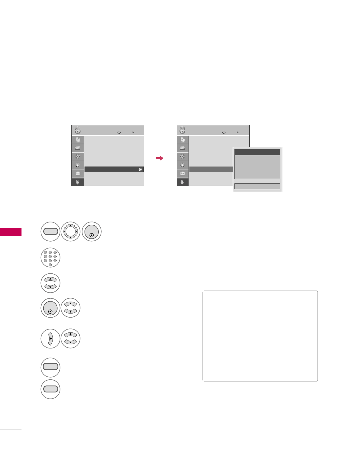
PARENTAL CONTROL / RATINGS
84
PARENTAL CONTROL /RATINGS
TV Rating General
Based on the ratings, blocks certain TV programs that you and your family do not want to view.
Select
AAgg ee
,
DDiiaalloogguuee
,
LLaanngguuaaggee
,
SSee xx
or
VViioolleennccee
.
4
3
ENTER
Select block options.
5
■
Age (applies to TV-G,TV-PG,TV-14,TV-
MA).
■
Dialogue-sexual dialogue (applies to
TV-PG,TV-14).
■
Language-adult language (applies to
TV-PG, TV-14, TV-MA).
■
Sex-sexual situations (applies to TV-PG,
TV-14, TV-MA).
■
Violence (applies to TV-PG, TV-14, TV-
MA).
Select
LLOOCCKK
.
1
MENU
ENTER
Input the password.
2
1
456
78
0
9
23
6
RETURN
Return to the previous menu.
MENU
Return to TV viewing.
Enter
Move
LOCK
Lock System : Off
Set Password
Block Channel
Movie Rating
TV Rating-Children
TV Rating-General
Downloadable Rating
Input Block
Enter
Move
LOCK
Lock System : Off
Set Password
Block Channel
Movie Rating
TV Rating-Children
TV Rating-General
Downloadable Rating
Input Block
Close
Age
GG
Dialogue
Language
Sex
Violence
PARENTAL CONTROL /RATINGS
Select
TTVV RRaattiinngg--GGeenneerraall
.

PARENTAL CONTROL / RATINGS
85
DOWNLOADABLE RATING
■
Based on rating table, your TV's OSD
(On Screen Display) may differ slightly
from what is shown in this manual.
This function may become available in the future and will be available only for digital channels.
This function operates only when TV has received Region5 Rating data.
Select
DDoowwnnllooaaddaabbllee RRaattiinngg
.
Select desired
DDoowwnnllooaaddaabbllee
RRaattiinngg
option.
4
3
ENTER
Select desired option and block it.
5
ENTER
Select
LLOOCCKK
.
1
MENU
ENTER
Input the password.
2
1
456
78
0
9
23
6
RETURN
Return to the previous menu.
MENU
Return to TV viewing.
Enter
Move
LOCK
Lock System : Off
Set Password
Block Channel
Movie Rating
TV Rating-Children
TV Rating-General
Downloadable Rating
Input Block
Enter
Move
LOCK
Lock System : Off
Set Password
Block Channel
Movie Rating
TV Rating-Children
TV Rating-General
Downloadable Rating
Input Block
Humor
Sport
Cruelty
Language
Sadness
Genre
Age
Close
E
E
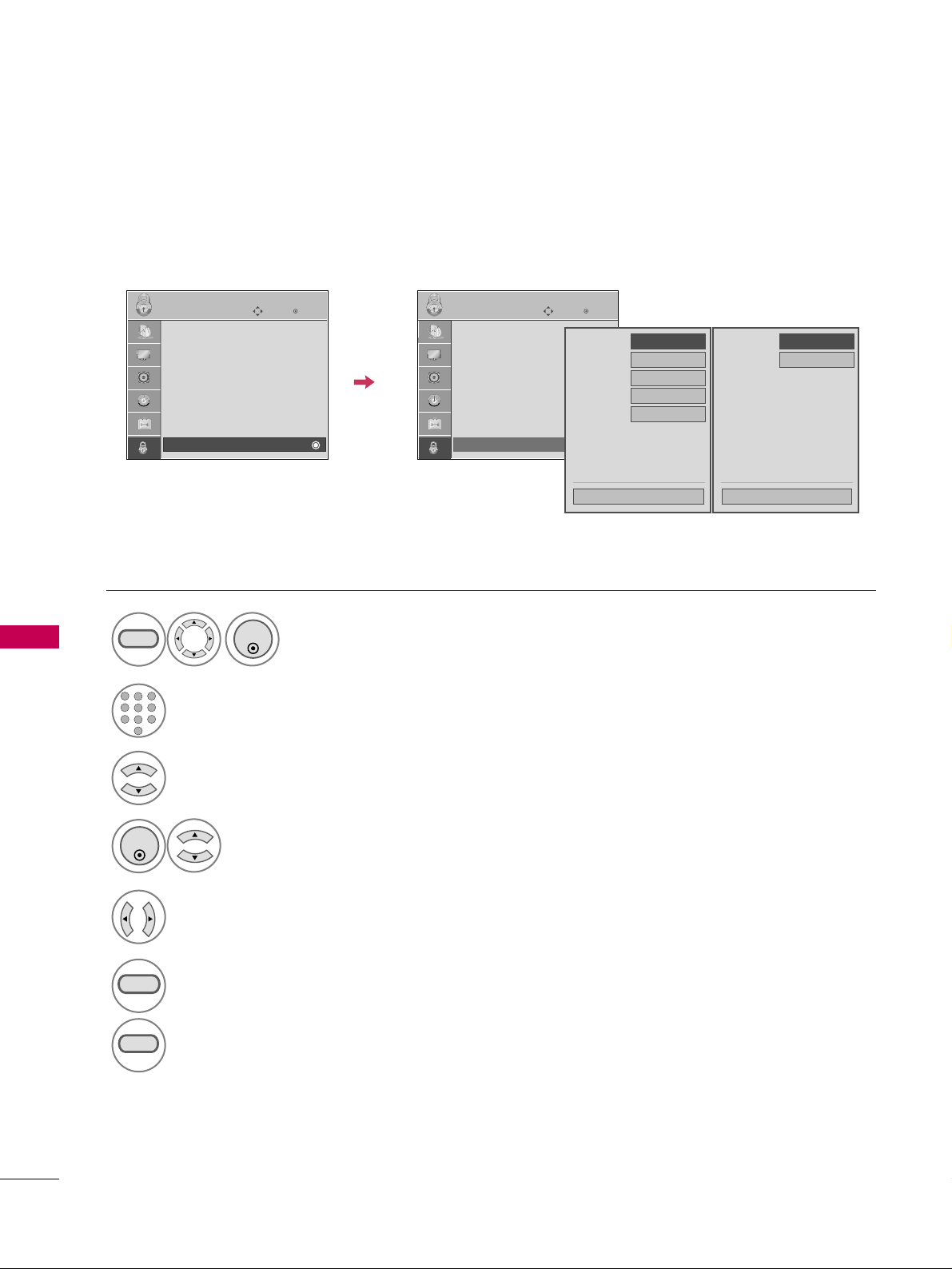
PARENTAL CONTROL / RATINGS
86
PARENTAL CONTROL /RATINGSPARENTAL CONTROL /RATINGS
EXTERNAL INPUT BLOCKING
Enables you to block an input.
Select
IInnppuutt BBlloocckk
.
Select input source.
4
3
Select
OO nn
or
OOffff
.
5
ENTER
Select
LLOOCCKK
.
1
MENU
ENTER
Input the password.
2
1
456
78
0
9
23
6
RETURN
Return to the previous menu.
MENU
Return to TV viewing.
Enter
Move
LOCK
Lock System : Off
Set Password
Block Channel
Movie Rating
TV Rating-Children
TV Rating-General
Downloadable Rating
Input Block
Enter
Move
LOCK
Lock System : Off
Set Password
Block Channel
Movie Rating
TV Rating-Children
TV Rating-General
Downloadable Rating
Input Block
AV1
FF
Off
GG
AV2
Off
Component
Off
HDMI
Off
RGB
Off
Close
FF
Off
GG
Off
Close
AV
HDMI
For 22LG3DCH For 26/32LG3DCH
32LG3DC
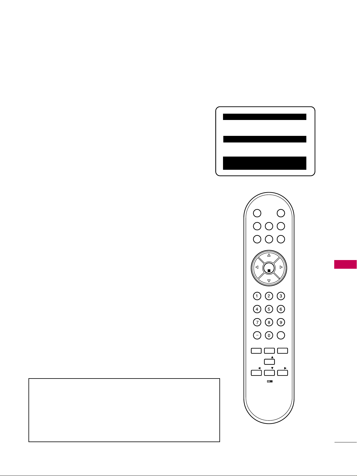
CHANNEL BANKS
87
CHANNEL BANKS
CHANNEL BANKS OVERVIEW (Except 32LG3DC)
Channel Banks Note: Disable all Aux sources in the Installer menu that will not be made available to the end
user.
CH 011-001 NORMAL-ADDED
Enter -> Change
CC ->VCHIP Menu Ch. Preview -> Exit
CHANNEL PREVIEW - BANK 1
CChhaannnneell BBaannkk SSeettuupp MMeennuu
Channel Banks Overview
Purpose of Channel Banks: Allows the institution administrator to control
access to patient in-room TV programming. A channel bank can be enabled
for a patient for a pre-determined fee. For Banks 1-2 and 3, the institution
can create programming levels. Each level would offer a custom channel line-
up. Top tier would be the most programming (premium etc.), 2nd tier=lesser
programming, 3rd tier=basic programming etc. Channel Bank 4 would dis-
play the ‘Inactive TV Call Attendant’ message when the TV is turned on. The
administrator could activate Banks 1-2 or 3 depending on the programming
tier selected by the patient. When the patient leaves the hospital, the admin-
istrator can then select Bank 4 to reinstate the Inactive TV message.
Channels Available Charts
All channels found in the channel search are included in all channel banks.
Default is for all channels to be active in channel banks 1-2-3 and 4. Create
channel banks charts similar to the examples on the following pages. Show on
the channel bank chart, the status for each channel in all channel banks. This
then becomes the patient entertainment programming offerings plan.
Channel Banks Setup
Operating the Channel Banks menu.
Note: Channel banks can only be set up after the 2-5-5+Menu procedure
has been completed. See remote key functions for channel banks menu on
the following page.
Channel Status Options Available for Channel Banks
In the Ch Preview-Channel Banks menu, use the channel up-down arrows to
go to a channel and the Left-Right arrows to select the channel status. See
channel status chart.
Inactive TV Setup
Go to Channel Bank 4. Select ‘Normal Delete’ for all channels. When the TV
is powered on by the patient, the ‘Inactive TV Call Attendant’ message will
appear on the screen and after a few moments the TV will turn itself off.
With the Installer remote, the administrator can activate Banks 1, 2 or 3
depending on the entertainment programming tier selected by the patient.
When the patient leaves the hospital, the administrator can then select Bank
4 to reinstate the ‘Inactive TV’ message.
Note: Default setting for Aux sources is to be active in the Installer menu. The Aux
sources will appear between the highest Analog and lowest Digital channel number
in the channel scan with Channel Up/Down. If the Aux sources will not be used, it
is advisable to set them to 000 (Off) before doing 2-5-5 + Menu. After doing 2-
5-5 + Menu, the only way to turn the Aux sources off so they will not appear in
the channel scan, is to go to the Channel Bank menus and select ‘Normal Delete’.
Refer to Installer menu items: 35 and 39.
3140OSKZ003AR6
MUTE
POWER
BANK
GUIDE
CH
PREVIEW
SAP
INFO
CC
OK
VOL
CH
CH
VOL
FLASHBK
TIMER
ALARM
MENU
ADJ
ADJ
ADJ
ADJ
BED1
BED2
Use to access Ch Preview Menu
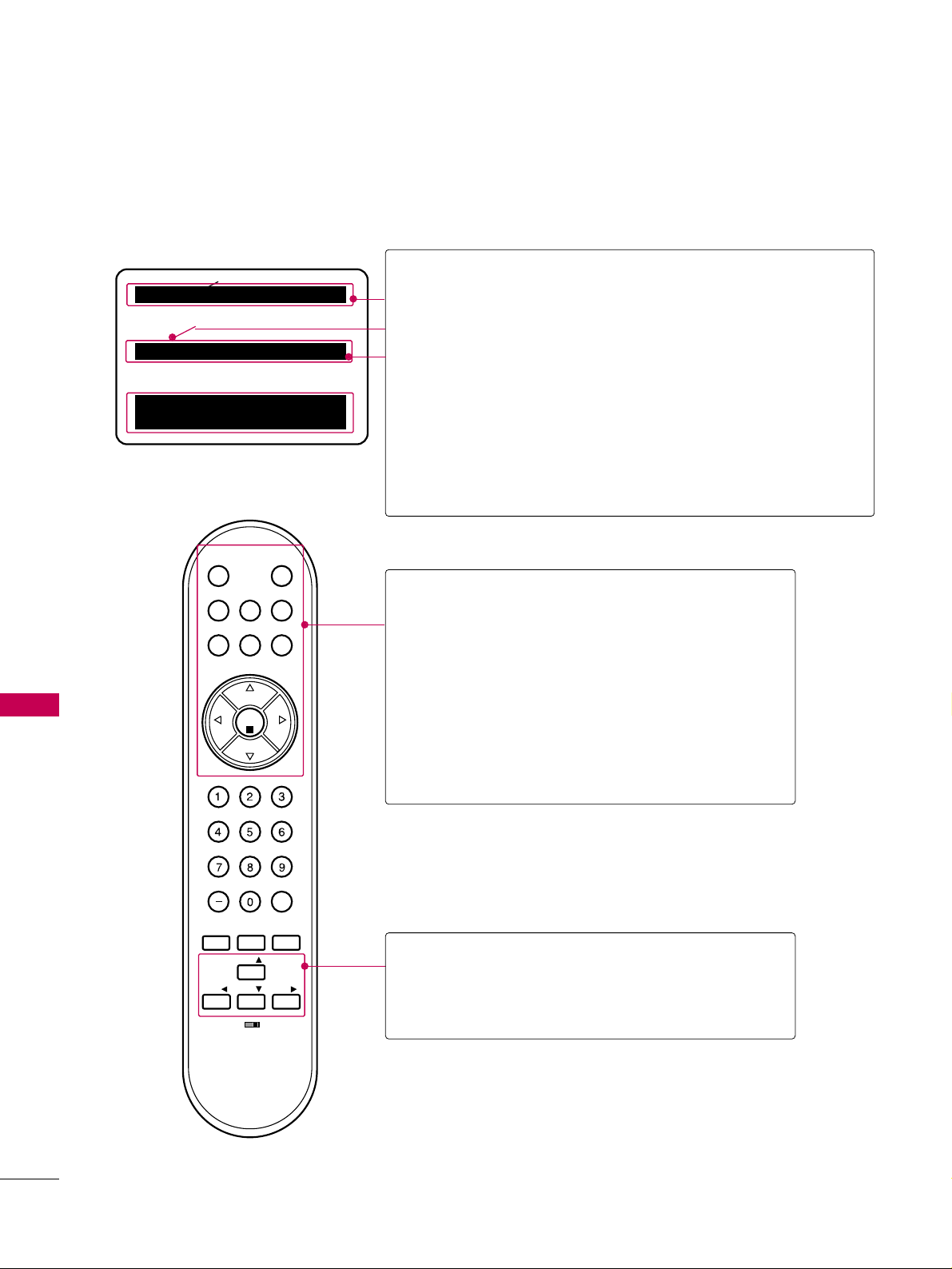
CHANNEL BANKS
88
CHANNEL BANKS
CHANNEL BANKS SETUP INSTALLER REMOTE CONTROL KEY
FUNCTIONS (Except 32LG3DC)
Channel Banks Setup Remote Control Key Functions
After doing 2-5-5 + Menu, select a channel bank with the
input/source or Banks button. After desired bank is selected, press Ch
Preview to display the Channel Banks editing menu.
Shows currently selected Channel Bank.
Shows currently selected Channel.
Shows channel status in selected bank.
IInn CChhaannnneell BBaannkkss mmeennuu,, uussee tthhee LLeefftt--RRiigghhtt aarrrroowwss ttoo sseelleecctt::
Normal-Added Channel will appear in channel scan.
Normal-Deleted Channel will not appear in channel scan.
Blank-Added Channel will appear in all channel banks,
video will be black, no picture.
Blank-Deleted Channel will be blanked in all channel banks.
Bank
Ch Preview
Channel Up
OK (Enter)
Channel Down
Selects channel banks 1-2-3-4.
Selects channel banks setup menu.
Exits menu.
Selects next higher channel number.
Tunes in deleted channels in scan.
Selects next lower channel number.
3140OSKZ003AR6
MUTE
POWER
BANK
GUIDE
CH
PREVIEW
SAP
INFO
CC
OK
VOL
CH
CH
VOL
FLASHBK
TIMER
ALARM
MENU
ADJ
ADJ
ADJ
ADJ
BED1
BED2
CH 011-001 NORMAL-ADDED
Enter -> Change
CC ->VCHIP Menu Ch. Preview -> Exit
CHANNEL PREVIEW - BANK 1
Channel Bank Setup Menu
Typical Installer Remote Control
Up-Down
Left-Right
Tune to added channels in menu.
Choose menu options.
Up/Down Left/Right ADJ Arrows
Note: Pressing CC Displays V-Chip menu.

CHANNEL BANKS
89
CHANNEL BANKS SETUP (Except 32LG3DC)
Use the Channel Banks to format the channel lineup programming package options for the end user
Each channel bank is capable of storing broadcast digital and analog channels
Figure 1. Typical channel banks after running Auto Tuning
B
A
N
K
1
2
3
4
A
A
A
A
A
A
A
A
A
A
A
A
A
A
A
A
A
A
A
A
A
A
A
A
A
A
A
A
A
A
A
A
A
A
A
A
A
A
A
A
A
A
A
A
A
A
A
A
A
A
A
A
A
A
A
A
A
A
A
A
Purpose
Channel Number
123 4 5 6 7 8 9 1011121314151617181920212223242
A = Active - - Channel was found during AU TO TUNING
Figure 2. Typical channel banks after running Auto Tuning, and customizing with Add/Del/Blnk
B
A
N
K
1
2
3
4
Basic
Extend
All CTV
Oth
er
A
A
A
A
BC
BC
BC
BC
A
A
A
A
A
A
A
A
A
A
A
A
A
A
A
A
D
A
A
A
D
D
D
A
D
A
A
A
D
D
D
A
D
A
A
A
D
A
A
A
D
A
A
A
D
D
A
A
D
D
D
A
D
D
A
A
D
D
A
A
Purpose
Channel Number
1234 5 6 7 8 9 10 11 12 13 14 15 16 17 18 19 20 21 22 23 24 2
A = Active Channel was found during AUTO TUNING
D = Delete Channel was deleted using Add/Del option.
BC = Blanked Channel Channel was blanked using BLANK channel option (ADD/DEL/BLNK).
5
5
Adding / Deleting / Blanking Channels
It is best to do ADD / DEL customizing before doing
“BLANK.” Auto Tuning (channel search) enters the
same channel numbers in channel banks 1, 2, 3 and 4.
Auto Tuning removes any channels previously cus-
tomized with ADD / DEL / BLANK. The channels found
in the channel search on your antenna / cable will be
included, and any channels previously found but not
currently available will not be included. ADD and DEL
(not BLANK) can be used independently for channel
banks 1, 2, 3 and 4. (If a channel is not found in the
channel search, it can be added see the Channel Menu
Manual Tuning option.)
NNootteess::
A channel blanked, is blanked in all channel
banks.
Selecting Deleted Channels
To tune to a Normal Delete channel: Select a Channel
Bank where the channel is added. Or, direct enter the
channel number then go to the bank where the chan-
nel is set as ‘Normal
Delete’ and reconfigure the channel status.
Note: Ch Override must be set to 001 to allow access
to the channel scan.
Channel allocations in tuning bands:
• Broadcast and Broadcast Digital: 2 - 69
• CABLE - CATV, HRC or ICC: 1 - 125
Inactive TV Setup for Channel Bank 4
To create an inactive TV display on Channel Bank 4,
select ‘Normal Delete’ for every channel in Bank 4.
When Bank 4 is selected with the bank button on
installer remote, the ‘Inactive TV, call attendant’ mes-
sage will be shown on the TV screen. The TV will turn
itself off afterward. This will prompt the patient to
arrange for an available programming package on
Banks 1, 2 or 3.
CHANNEL BANKS
90
CHANNEL BANKS
REFERENCE: CHANNEL BANKS WORKSHEET (Except 32LG3DC)
Use the Channel Banks worksheet provided below to plan your program packages. Photocopy additional
worksheets as needed.
PLAN YOUR CHANNEL BANKS BY FILLING IN THESE CHARTS (or use photocopies)
B
A
N
K
1
2
3
4
Purpose
Channel Number
1234 5 6 7 8 9 10 11 12 13 14 15 16 17 18 19 20 21 22 23 24
2
B
A
N
K
1
2
3
4
Purpose
Channel Number
26 27 28 29 30 31 32 33 34 35 36 37 38 39 40 41 42 43 44 45 46 47 48 49
B
A
N
K
1
2
3
4
Purpose
Channel Number
51 52 53 54 55 56 57 58 59 60 61 62 63 64 65 66 67 68 69 70 71 72 73 74
B
A
N
K
1
2
3
4
Purpose
Channel Number
76 77 78 79 80 81 82 83 84 85 86 87 88 89 90 91 92 93 94 95 96 97 98 99 100
B
A
N
K
1
2
3
4
Purpose
Channel Number
101 102 103 104 105 106 107 108 109 110 111 112 113 114 115 116 117 118 119 120 121 122 123 124 125
5
50
75
Date _____________ Installer _____________________________________ Page ___ of ____
Location ______________________________________________________________________
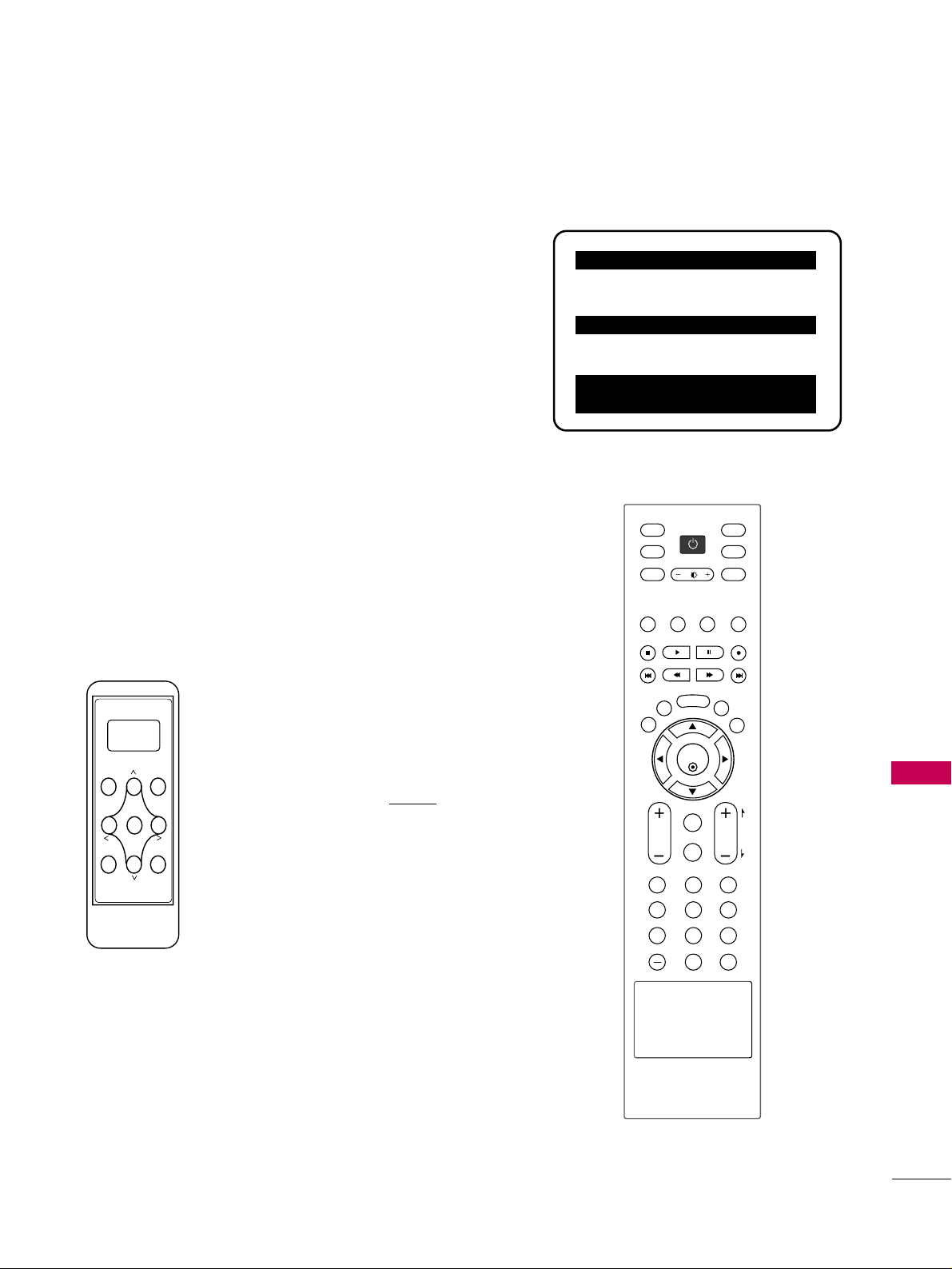
COMMERCIAL MODE SETUP
91
COMMERCIAL MODE SETUP
INSTALLER OVERVIEW
OOppeerraattiinngg IInnssttaalllleerr MMeennuu
To set up the controls for the TV you will need to know how to
enter the TV Installer menu and make changes to the default val-
ues. If necessary, familiarize yourself with the TV Installer menu
and how to make and save changes to the items in the menu.
LLGG IInnssttaalllleerr RReemmoottee
You will need an
LLGG IInnssttaalllleerr rreemmoottee
control similar to the
one shown to the right. The installer remote must have a “Source”
button or its equivalent. The remote shown for reference in this
manual has “INPUT” -- this button serves the purpose of a Source
button.
The TV’s clonable features need to be set up. This is a critical
step. If the Master TV display panel’s clonable features like added
channel icons or channel labels are not done correctly, then the
cloned TVs will all have problems. Refer to the TV menus for
other TV features: Picture, Audio, Option, Closed captions, Lock
(V-Chip), etc.
TTLLLL--11110000AA CClloonnee PPrrooggrraammmmeerr
The TLL-1100A is a very simple cloner to use. It
can be set up to clone a master TV setup and
transfer it into a target TV. Cloning is possible
using MPI protocol. Be sure the Master TV is
set up completely. Cloning is only possible
when the signal source is an Analog
channel,
not a digital channel. Refer to TLL-1100A
instruction manual supplied with the cloner.
Typical Installer Menu
TV Link
Loader-Demo
TLL1100A
Ready
TLL1100A
ENTER
RECEIVE SEND
MENU
MODE
ENTER
TVTV
INPUT
INPUT MODE
DVD
MULTI
EXIT
VOL
EZ SOUND
INFO
SWAP
EZ PIC
TIMER
MUTE
CH
SAP
CC
RATIO
MENU
VCR
POWER
123
456
789
0
FLASH
BACK
PAG E
000 INSTALLER SEQ 000
UPN 000-000-000-000 FPGA E0F1
PTC V1.00.000 CPU V3.06.00
HOSPITAL PTC INSTALLER MENU

COMMERCIAL MODE SETUP
92
COMMERCIAL MODE SETUP
TV OVERVIEW
Using a Hospital Grade TV, the patient has available the following entertainment options.
• Pillow Speaker control of TV.
• Auxiliary inputs connections panel, if enabled.
• Analog and Digital programming entertainment as provided by hospital:
VHF, UHF, DTV, CATV, CADTV.
• 22 Inch screen size.
• 16:9 Aspect Ratio.
• Auto Volume sound control
• Digital Captions
• Tier programming as available through Channel Banks setup, RF delivered programming
content options for premium as well as basic entertainment packages.
• Headphone(s) output jack.
NNootteess
• See the Installer’s menus to set up the operational features of the TV. The Installer’s section content is intended
to be used primarily by qualified TV electronics technicians.
• Reference is made to installer remote controls used for menu operation within the manual. The remote informa-
tion is provided for reference only. The typical installer remote control shown for reference in this manual may
be different than the actual remote control used to configure the TV.
• For any additional information, contact your LG representative.
Note: Design and specifications are subject to change without prior notice.

COMMERCIAL MODE SETUP
93
COMMERCIAL MODE SETUP FOR MASTER TV
This page provides an overview of the TV configuration. See the pages referenced for more specific, detailed
instructions at each step; how to access and use the Installer menu etc.
NNoottee 11::
Disconnect all Aux inputs. Under certain conditions, Auto Tuning
(Channel search) is disabled if there is an Aux input active.
OOvveerrvviieeww:: CCoommmmeerrcciiaall MMooddee SSeettuupp PPrroocceedduurree
11.. SSeett IInnssttaalllleerr MMeennuu IItteemmss
(Enter TV Installer Menu, see Installer menus for detailed instructions.)
a. Set Installer menu item
111177 FFAACCTT DDEEFFAAUULLTT
,to
000011
and press
EENNTTEERR
on Installer remote. (This clears all installer menu custom set-
tings, channel labels / icons etc. and reloads the factory default settings.)
b. Set Item
000033 BBAANNDD//AAFFCC
.
-
BBrrooaaddccaasstt
: set to
000000
.-
HHRRCC
: set to
000022
-
CCAATTVV
: set to
000011
.-
IIRRCC
: set to
000033
c. Set item
002288 CCHH OOVVEERRIIDDEE
to
000011
. This allows access to Auto Tuning,
Manual Tuning and Channel Edit submenus in the Channel Menu.
d. Set other particular installer items that affect your TV programming net-
work. Enable/Disable Aux sources etc. See Installer menu pages.
Note: Disable all Aux sources that will not be active.
e. After all required installer menu item settings have been adjusted, press
ENTER on the remote to remove Installer Menu.
22.. SSeett UUpp TTVV FFeeaattuurreess ((SSeeee TTVV MMeennuuss sseeccttiioonn))
Channel, Picture, Sound, Lock, Time, Option (Digital Captions etc).
See TV Clonable Options page.
33.. RRuunn AAuuttoo TTuunniinngg ((CChhaannnneell SSeeaarrcchh))
(Search for all available channels.) Go to the Channel menu and access
the Auto Tuning option, follow onscreen instructions.
a. Edit Channel Scan. In the Channel Menu, access Channel Edit.
• Add/Delete channels per your system requirements.
Note: Physical channel numbers are used to identify Virtual channels.
• Add familiar Channel Trademarks/Logos like ABC, CBS, NBC etc. to the
Channel-Time onscreen display. In the Setup menu, select the Channel
Label option. Add identifiable labels for the end user to readily know what
common networks are available.
44.. TTrraannssffeerr TTVV SSeettuupp ttoo IInntteerrnnaall TTVV CCoonnttrroolllleerr:: 22--55--55 ++ MMeennuu MMooddee
After the TV channel scan has been edited and channel label icons added,
enter the Installer menu. Once in the Installer menu, press 2-5-5 and MENU
on the remote. This transfers the TV setup to the internal controller box.
Note: The maximum number of channels including Aux sources that can be
transferred to the TV controller is 140.
55.. AAdddd CCuussttoomm CChhaannnneell LLaabbeellss ffoorr aannaalloogg cchhaannnneellss:: 22--55--44 ++ MMeennuu MMooddee
Enter Installer menu, press 2-5-4 and Menu. Add your own custom text
labels to channel onscreen displays. Note: Digital Channels often have a
broadcaster generated text label. When done to exit mode, press
MMEENNUU
.
66.. VVeerriiffyy TTVV SSeettuupp
At this point, verify that the channel lineup, channel icons and custom labels
are correct. Make sure the TV features are set per your requirements. Set
Installer menu item
002288 CChh OOvveerriiddee
to
000000
to lock the channel scan.
After the preceding has been completed, the Master TV setup is ready to be
copied to a Clone Programmer, see Clone programmer pages.
003 BAND/AFC 00X
028 CH. OVERIDE 001
117 FACT DEFAULT 00X
Typical TV Installer Menu
Review the settings for these
Installer Menu Items
DIGITAL 19-3
WXYZ
MONO
STEREO SAP
Custom Channel Label ‘WXYZ’ created in
2-5-4 + Menu (Add Channel Label) Mode
028 CH. OVERIDE 000
After Master TV setup has been completed,
set Installer menu item 028 Ch Overide to
000. This action locks the channel scan.
000 INSTALLER SEQ 000
UPN 000-000-000-000 FPGA E0F1
PTC V1.00.000 CPU V3.06.00
HOSPITAL PTC INSTALLER MENU
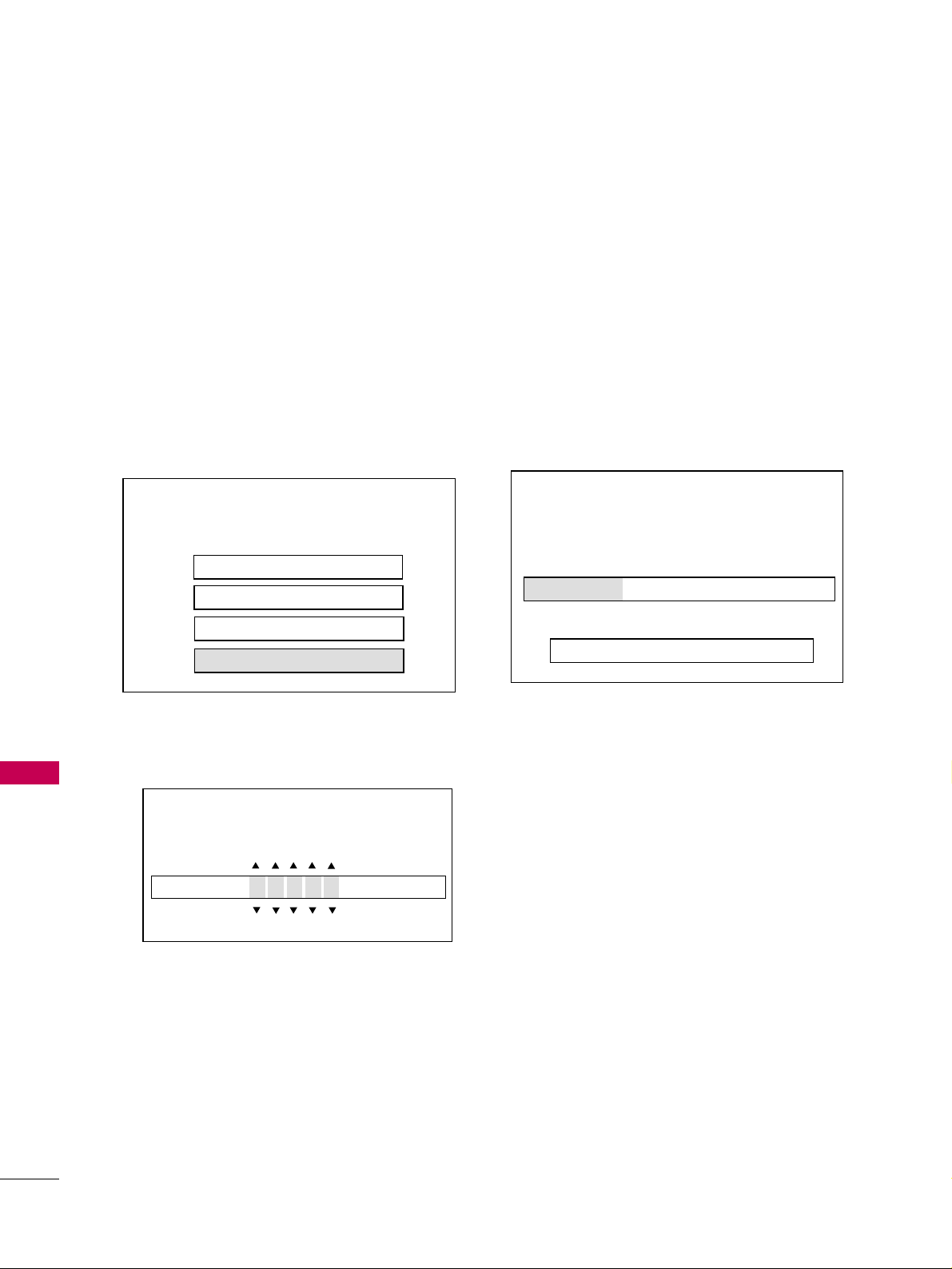
COMMERCIAL MODE SETUP
94
COMMERCIAL MODE SETUP
Upgrade TV Software
Select a type of sofware to be downloaded:
Upgrade TV Software
Upgrade PTC Software
Teach To TV
Learn From TV
On Master TV, Create Profile and Learn
MASTER TV PROFILE SETUP LEARNING/TEACHING WITH USB
MEMORY CARD
Optional: Edit/Change File Name
If necessary, the file name can be edited or changed.
Notes
• Do not remove TV power cord or USB memory card
while Learning, doing so might harm your USB memory
card.
• Do not remove TV power cord or USB memory card
while Teaching, doing so may cause the TV to malfunc-
tion.
• You are allowed to edit the file name, however, a file with
edited contents will not be recognized.
• Since clock data is copied into USB memory card as
numeric data, the time difference between teaching and
learning is not automatically adjusted. Either set the
clock manually, or use Auto Clock set on TV main menu.
Learn From TV
Choose the name of the image file:
32LG3DC_UA_ a a c c c .TLL
1. Set up all Master TV features on the menus and do
a Channel Search. Add Channel and Aux Labels etc.
Tune in an analog channel.
2. Plug USB memory card into the USB In port on
Master TV.
3. Press Menu key to open Main menu. Highlight the
Option icon.
4. Press the Left arrow key once, the Option icon on
left side of menu will be highlighted.
5. Press number key ‘7’ a total of 7 times.
6. Key in password* used to enter Installer Menu.
7. Using Up/Down arrow key, highlight “Learn Current
Profile’, then press Enter.
8. To identify the profile from others, you can change
the last 5 digits. Key in a custom file name, then
press the Enter key.
9. The Learning status will be shown on progress bar.
As soon as learning the current profile is complete,
a message will appear on screen indicating the
learning process is done.
10. Remove the USB memory card.
Learn From TV
Learning current profile from master TV:
20%
Do not unplug until restart automatically
* See Installer Menu pages.
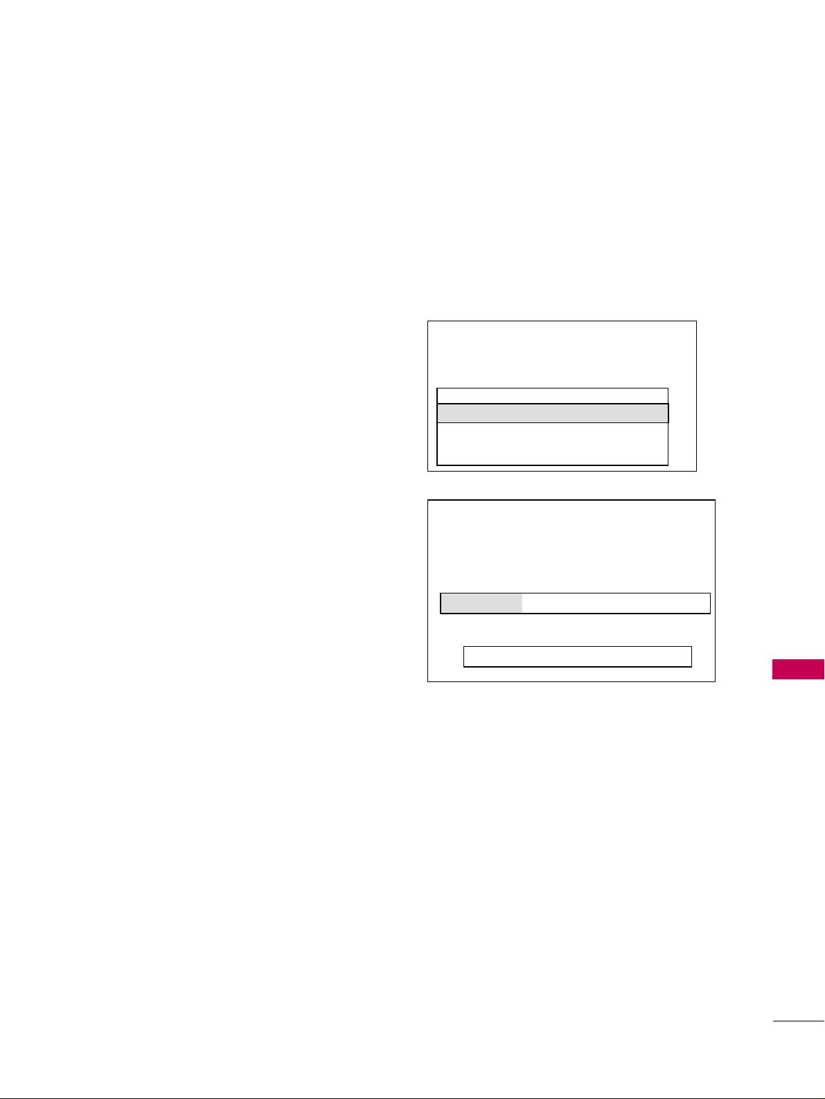
COMMERCIAL MODE SETUP
95
1. Plug USB memory card with Master TV Profile setup
into Target TV USB input port.
2. Press Menu key to open Main menu and then high-
light the Option Menu icon.
3. Press the Left arrow key once, this will highlight the
Option icon on left side of menu.
4. Press number key ‘7’, a total of 7 times.
5. Using the Up/Down arrow key, select ‘Teach New
Profile’, then press Enter key.
6. Use Up/Down arrow keys to navigate through pro-
files. Select the profile that you want to install by
highlighting it and pressing the Enter key.
7. Teaching progress will be shown on the progress bar.
As soon as teaching is done, a message will appear
indicating that the teaching process has been com-
pleted.
Teach Current Profile
Teaching the selected profile to the TV:
20%
Do not unplug until restart automatically!
On Target TV, Teach Master TV Profile
Teach To TV
The following software files are found in the memory card.
Select the file you want to download to this TV.
Or, Press EXIT to cancel the upgrade.
Software File List in USB Memory
32LG30_UA_ 128.TLL
32LG30_UA_ 126.TLL
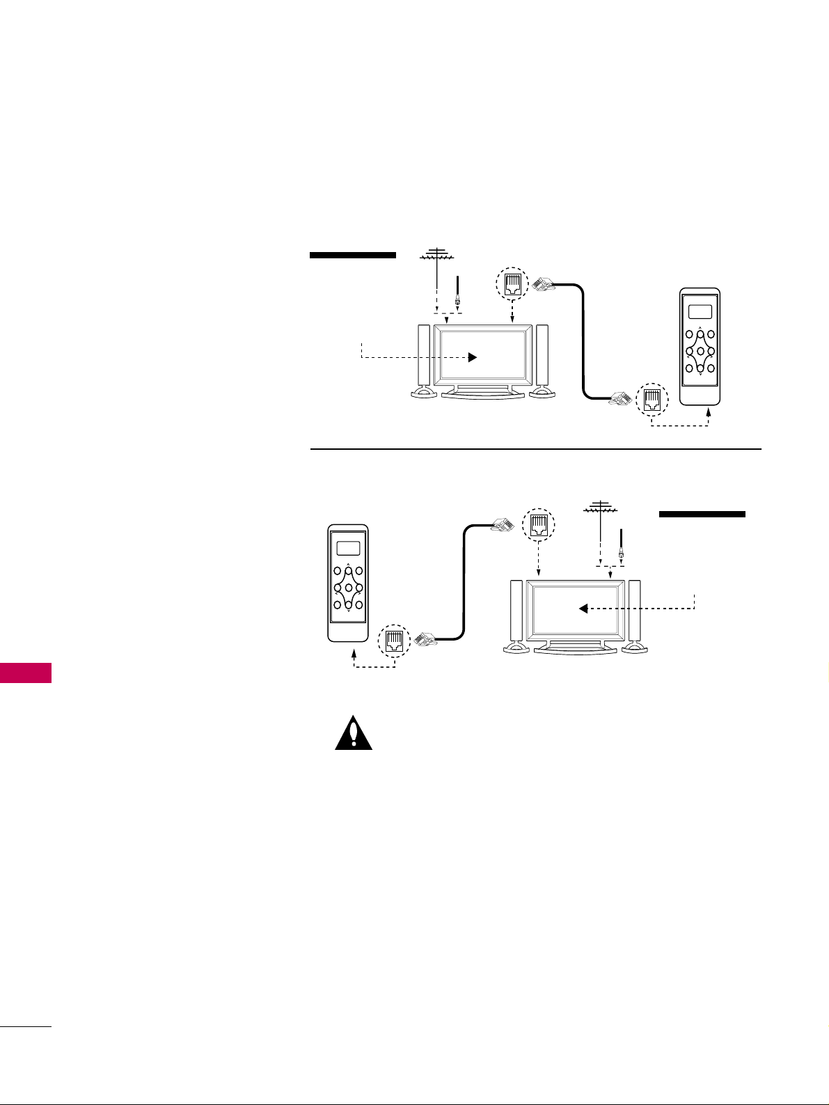
COMMERCIAL MODE SETUP
96
COMMERCIAL MODE SETUP
TLL-1100A CLONE CONNECTIONS/LEARNING AND
TEACHING SETUPS
Connections for the TLL-1100A Clone Programmer to Learn the Master TV Setup
Antenna
(or CATV)
Antenna
(or CATV)
TV Link
Loader-Demo
TLL1100A
Ready
TLL1100A
ENTER
RECEIVE SEND
MENU
MODE
CLONE SELECTION MENU
Selected Bank: CBank X Saved
(1) LEARN FROM TV
(2) TEACH TO TV
(3) SET CLONE CLOCK FROM TV
(4) SET TV CLOCK FROM CLONE
(5) DISPLAY TV SETUP
(6) DISPLAY CLONE SETUP
CLONE CLOCK = 00:00
TV CLOCK = 00:00
THE CLONE IS VERSION V2.2.2
-To change menu items, Press
channel keys or digits.
-To execute item, Press ENTER.
M.P.I. Learning Setup
M.P.I. Teaching Setup
TV Link
Loader-Demo
TLL1100A
Ready
TLL1100A
ENTER
RECEIVE SEND
MENU
MODE
NNootteess::
It is assumed that the TV is connected to a signal
source, the TV source selected is Antenna (RF) In, the signal is
from an Analog channel, not a digital channel, all equipment is
connected to power and turned on and the TLL-1100A Cloner
main menu is displayed on the TV screen, see above.
Warning: Do not use the TLL-1100A while any PPV card is
installed or clone programmer device will be damaged.
OOnn MMaasstteerr TTVV
Set up all Master TV features on
the menus and do a Channel
Search. Add Channel and Aux
labels etc. Tune in an analog
channel. Insert MPI cable into TV
MPI port.
OOnn TTLLLL--11110000AA
1. Turn On the TLL-1100A.
2. Use the Mode button to select
Clone Mode.
3. Use the Left/Right arrow to
select the CBank (1 - 8) to
store the master TV setup in.
4. Plug the other end of the MPI
cable into the MPI port on the
bottom of the TLL.
5. With the Installer remote con-
trol, select item 1 on TLL
menu.
6. Press Enter, to transfer the
Master TV setup into CBankX
on the TLL. The TLL will copy
the master TV setup.
7. When learning is done, discon-
nect MPI cable from Master
TV.
OOnn TTaarrggeett TTVV
1. Connect MPI cable from the
TLL to the MPI port on the
Target TV. Assure that the
correct CBank(X) is selected
on TLL.
2. With the Installer remote con-
trol, select item 2 to Teach
the target TV the master TV
setup.
3. Press Enter to begin teaching.
4. When Teaching is done, dis-
connect MPI cable and power
the TV Off. Unplug TV power
cord.
5. Reconnect TV power cord.
Power the TV On and the
master TV setup should be
resident on the target TV.

COMMERCIAL MODE SETUP
97
LT2002 CLONING CONNECTIONS/LEARNING SETUP
Connections for the LT2002 Clone Programmer to Learn the TV Master TV Setup
• The Master TV should be connected to a good, sta-
ble signal from an over-the-air antenna or cable ser-
vice Analog
channel and connected to power. (See
above.)
• Teaching and Learning is only possible between iden-
tical model TV/STBs. (However, the LT2002 Clone
programmer can store up to 3 different ‘master’
setups.)
WARNING: Copying a blank or incorrect memory into
a TV, STB or other device will cause the TV, STB or
other device to operate erratically or become inoper-
able.
• Use an Installer’s remote to operate Learning and
Teaching menus.
• Make sure that the batteries in the Clone program-
mer are fresh.
• If batteries are removed, the Clone Clock time will be
lost.
• Decide if you want to set the time from the Clone
programmer or copy the time to the Clone program-
mer; from a compatible TV which has had the clock
set to the current time.
• Setting the time and transferring it to the Clone or
other device is a separate procedure.
• Follow the connection diagram above to connect the
Clone to a Master TV display panel. After learning is
complete, to another identical TV display panel to
“teach” it the master TV setup.
• See the Clone Troubleshooting section to resolve
problems.
TTuurrnn ttoo tthhee nneexxtt ppaaggee ttoo ccoonnttiinnuuee CClloonniinngg
SSeettuupp..
QuickSet II Programmer
LT2002
Ferrite Core
(TDK, ZCAT
2035-0930)
• heartbeat power on
communications ok
• slow power on
no communications
• green battery ok
• red battery low
Blink pattern
Color
Reset
Status
Indicator
Connect cable to
TV MPI Jack and
follow on screen
instructions
MPI
THE CLONE HAS CONTROL OF THE TV
THE CLONE IS VERSION XX
THE TV IS VERSION XX
THE SW IS REVISION XX
CLONE CLOCK = XX:XX
TV CLOCK = XX:XX
-PRESS ANY KEY TO CONTINUE.
-DISCONNECT CLONE WHEN DONE.
Antenna
or CATV
Master TV
Clone Programmer
Notes: It is assumed that the TV is connected to a signal source, the source selected is Antenna (RF) In, the sig-
nal is from an Analog channel, not a digital channel, all equipment is connected to power and turned on and the
LT2002 Clone Programmer main menu (THE CLONE HAS CONTROL OF THE TV) menu is displayed on the TV
screen, see above and next page.
Warning: Do not use LT2002
while any PPV card is installed
in TV or clone programmer
device will be damaged.
Before you begin cloning...
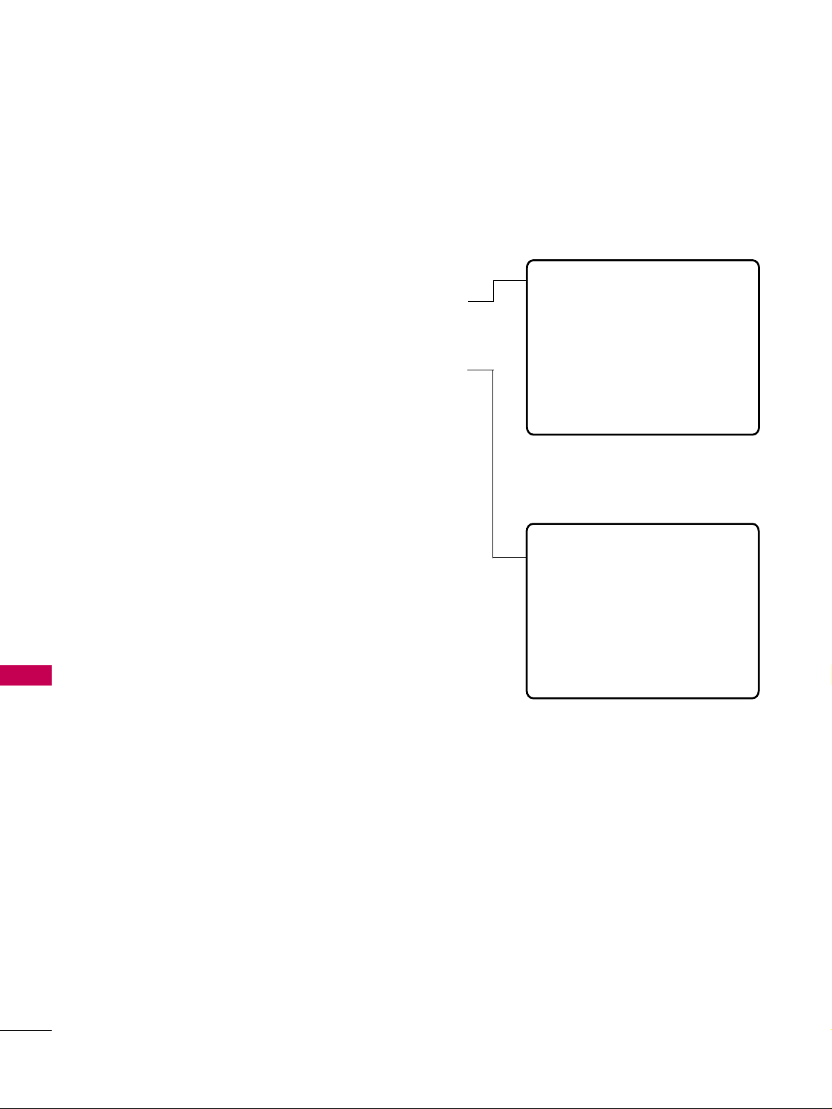
COMMERCIAL MODE SETUP
98
COMMERCIAL MODE SETUP
CLONING LEARNING SETUP
Learning the Master TV Setup
Instructions for the Clone Programmer to Learn the Master TV Setup
Use MPI Cable to Connect LT2002 Clone
Programmer to Master TV MPI Port
If there is a good connection, “THE CLONE HAS CONTROL OF TV”
message will appear. Press any key on the Installer remote.
Learn Setup from Master TV
Press 1 to select the “LEARN FROM TV” option, then press
ON/OFF, POWER, or ENTER to go to the Memory Bank
Selection Menu. Pick the Memory ”Bank” you want to store
the master TV’s setup in by pressing either Channel key
repeatedly to choose Memory 1, 2 or 3. (If you choose a
Memory “Bank” that has a master device’s setup programmed
into it, that setup will be overwritten by the new master TV’s
setup.) Once the Clone memory bank is selected, press
ON/OFF, POWER, or ENTER. The Clone memory bank you
have selected will be shown. Press ON/OFF or POWER to
begin copying the master TV’s setup.
Set the Clock (Optional)
Set the time on a Master TV’s Clock. (If the time has already
been copied from a TV into the Clone programmer, you can
set a master TV’s clock by copying the time from the Clone
programmer.) The Clone Programmer can copy the current
time to both a master TV and to the Clone’s internal clock;
accurate to within one minute. (Another reason that the Clone
programmer should be equipped with fresh, high-quality alka-
line batteries, is for it to keep the time as accurately as possi-
ble.)
Since the Clone Programmer’s time cannot be set directly, the
current time needs to be copied from a Zenith/LG TV
equipped with M.P.I. input capability.
After the time is copied to the Clone programmer, the current
time can then be transferred to another TV. (This can be a
master TV, or another TV which has already had the features
set up.)
LT2002 Clone Programmer Communication
Problems
• A slow flashing green light indicates there are
communication problems between the TV and
the LT2002 clone programmer. If this is the
case, check for a damaged cable, poor con-
tacts, or other connection troubles.
• If the status indicator is red, the programmer
batteries are low and should be replaced.
Install 4 high-quality alkaline AA batteries.
THE CLONE HAS CONTROL OF THE TV
THE CLONE IS VERSION XX
THE TV IS VERSION XX
THE SW IS REVISION XX
CLONE CLOCK= XX:XX
TV CLOCK= XX:XX
-PRESS ANY KEY TO CONTINUE.
-DISCONNECT CLONE WHEN DONE.
CLONE SELECTION MENU
(1) LEARN FROM TV
(2) TEACH TO TV
(3) SET CLONE CLOCK FROM TV
(4) SET TV CLOCK FROM CLONE
(5) DISPLAY TV SETUP
(6) DISPLAY CLONE SETUP
-TO CHANGE MENU ITEMS, PRESS
CHANNEL KEYS OR DIGITS.
-TO EXECUTE ITEM, PRESS ON/OFF,
POWER, OR ENTER
This menu should appear by itself after
the LT2002 is connected to the TV MPI
port.
This menu should appear after any key is
pressed on the Installer remote.
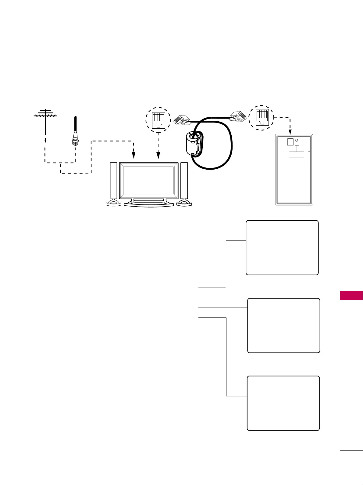
COMMERCIAL MODE SETUP
99
CLONING CONNECTIONS/TEACHING SETUP
Teaching the Master Setup to Another TV
Connections for the LT2002 to Teach another TV the Master Setup
QuickSet II Programmer
LT2002
• heartbeat power on
communications ok
• slow power on
no communications
• green battery ok
• red battery low
Blink pattern
Color
Reset
Status
Indicator
Connect cable to
TV MPI Jack and
follow on screen
instructions
MPI
Ferrite Core
(TDK, ZCAT
2035-0930)
THE CLONE HAS CONTROL OF THE TV
THE CLONE IS VERSION XX
THE TV IS VERSION XX
THE SW IS REVISION XX
CLONE CLOCK = XX:XX
TV CLOCK = XX:XX
-PRESS ANY KEY TO CONTINUE.
-DISCONNECT CLONE WHEN DONE.
Antenna
or CATV
Target TV
Clone Programmer
TTeeaacchh MMaasstteerr TTVV’’ss SSeettuupp ttoo tthhee ttaarrggeett TTVV
After learning is complete, remove the M.P.I. cable from the mas-
ter TV and connect it to the target TV that you want to copy the
master TV’s setup into. With “THE CLONE HAS CONTROL OF
TV” message displayed, press 2 or use either Channel key to go
to the “TEACH TO TV” option, press ON/OFF, POWER, or
ENTER. Select the LT2002 memory that the new setup is in.
Press On/Off to transfer the new setup and other information to
the new TV. Teaching usually takes 2-3 minutes.
After the “TEACHING COMPLETE” message is displayed, press
any key to return to the Clone menu, then press ON/OFF,
POWER, or ENTER. If finished, detach M.P.I. cable from the
target, newly-cloned TV.
DDiissccoonnnneecctt TTVV PPoowweerr ffoorr 1155 SSeeccoonnddss
Unplug the AC power cord of the newly-cloned TV from the
power outlet for about 15 seconds to activate the newly-copied
setup.
TEACHING IN PROGRESS,
PLEASE WAIT
TEACHING COMPLETE
This display will appear after
Teaching is complete.
This display will appear dur-
ing Teaching function.
CLONE SELECTION MENU
(1) LEARN FROM TV
(2) TEACH TO TV
(3) SET CLONE CLOCK FROM TV
(4) SET TV CLOCK FROM CLONE
(5) DISPLAY TV SETUP
(6) DISPLAY CLONE SETUP
-TO CHANGE MENU ITEMS, PRESS
CHANNEL KEYS OR DIGITS.
-TO EXECUTE ITEM, PRESS ON/OFF,
POWER, OR ENTER
This menu should appear after
any key is pressed on the Installer
remote.

COMMERCIAL MODE SETUP
100
COMMERCIAL MODE SETUP
INSTALLER MENU
Use the Installer’s Menu to set up or change operational settings.
See more detailed descriptions of the Installer menu items on the following pages...
AAcccceessssiinngg tthhee IInnssttaalllleerr’’ss MMeennuu
Make sure TV is on. Installer’s menu items can be accessed by using
an installer’s remote control. Just press MENU repeatedly until the TV
seems to stop responding, then press 9, 8, 7, 6, and ENTER to access
the Installer’s menu. To remove the Installer’s menu, press ENTER
again.
Any changes you make will be stored in nonvolatile memory.
The Installer’s menu opens with item 000 INSTALLER SEQ 000. Use
the Up/Down arrow keys to sequence through the available menu
items. Or, access an item directly by keying in the line number, then
pressing MENU. For example, to access the Sleep Timer option which
is item 015, press 0-1-5, then MENU. To change a setting, use the
Left/Right arrow keys. Or, enter a value directly.
UUssiinngg tthhee IInnssttaalllleerr’’ss MMeennuu
Items 000
~ 118 are immediately accessible only upon entering the
Installer’s Menu. Their numbers, descriptions, ranges, factory default
settings, and a place for listing any changes made on-site are given
below and on the following pages.
Typical Installer Menu
000 INSTALLER SEQ 000
UPN 000-000-000-000 FPGA E0F1
PTC V1.00.000 CPU V3.06.00
HOSPITAL PTC INSTALLER MENU

COMMERCIAL MODE SETUP
101
Menu Item Function Value Range Default Value Brief Description of Function and Comments
000 INSTALLER SEQ 0 ~ 3 0 Leave default set to 0.
001 POWER MANAGE 0 ~ 7 0 Sets number of hours of no activity before auto shut Off.
002 AC ON 0 / 1 0 Set to 1 to enable auto turn On at power up.
003 BAND/AFC 0 ~ 3 1 Selects Tuning Band: 0=Broadcast, 1=CATV, 2=HRC, 3=IRC
004 STRT CHANNEL 0 ~ 127, 255 255 Channel at turn-on (Set to 255 to tune in last channel before power Off).
005 CHAN LOCK 0 / 1 0 If set to 1, cannot tune from current channel.
007 STRT VOLUME 0 ~ 63, 255 255 Sets Volume level at TV turn-on (Set 255 to retain last volume level).
008 MIN VOLUME 0 ~ 63 0 Sets minimum allowable volume setting.
009 MAX VOLUME 0 ~ 63 63 Sets maximum allowable volume setting.
010 MUTE DISABLE 0 / 1 0 Set to 1 to disable mute function.
011 KEY DEFEAT 0 / 1 1 Set to 1 to disable menu navigation keys on TV.
012 IR BANKS EN. 0 / 1 0 Set to 1: enables TV to respond to IR code
013 SCAN MODE 0 / 1 1 Typically used for Hospitals: puts TV On-Off event in Ch Up/Down sequence.
014 STRT CH IN SM 0 / 1 0 Set to 1 to put TV On/Off below start channel number.
015 SLEEP TIMER 0 / 1 1 Set to 1 to enable Sleep Timer.
016 EN TIMER 0 / 1 1 Set to 1 to enable On/Off Timers.
017 ALARM 0 / 1 1 Set to 1 to enable Alarm.
020 FEATURE LEVEL 0 / 1 1 Zen 1 Leave default set 1 (1 Zen 1)
021 V-CHIP 0 / 1 1 Set to 1 to enable V-Chip functions.
022 MAX BLK HRS 0 ~ 99 12 Sets the number of V-Chip (Parental Control) blocking hours.
023 CAPTION LOCK 0 / 1 0 Set to 1 to retain caption setting at power Off.
025 FUNCTION PRE. 0 ~ 3 1 Controls channel preview in Pay-Per-View function
027 HOSPITAL MODE 0 ~ 2 2 Leave default set to 2.
028 CH. OVERIDE 0 / 1 1 If set to 0, limits direct access to only channels in TV memory.
029 OLD OCV 0 / 1 0 Set to 1 to change M.P.I. operation to OCV.
IInnssttaalllleerr MMeennuu IItteemmss 000000 tthhrroouugghh 2299

COMMERCIAL MODE SETUP
102
COMMERCIAL MODE SETUP
Menu Item Function Value Range Default Value Brief Description of Function and Comments
030 ACK MASK 0 / 1 0 If set to 1, changes M.P.I. for some OCV boxes.
031 POLL RATE 20 ~ 169 94 Selects poll rate for M.P.I.
032 TIMING PULSE 186 ~ 227 207 Sets baud rate for M.P.I.
035 COMPPORT EN. 0 / 2 1 Set to 0 to disable HDMI 1. Set to 1 for DTV.
039 REAR AUX EN 0 / 1 1 Set to 1 to enable display panel Video 1 input jack.
046 STRT AUX SRCE 0 ~ 6 3 Sets the starting AUX source.
047 AUX STATUS 0 / 1 0 Set to 1 for M.P.I. AUX source to be reported as a channel number instead of Channel 0.
053 DIS. CH-TIME M. 0 / 1 0 Set to 1 to disable Channel-Time display.
069 EN. CH-T COL. 0 / 1 1 Set to 1 to enable custom color for the Channel-Time display.
070 FOR. CH-TIME 0 ~ 7 2 Chooses custom foreground color for the Channel-Time display.
071 BCK. CH-TIME 0 ~ 7 2 Chooses custom background color for the Channel-Time display.
073 CH NOT AVBLE 0 / 1 0 If set to 1 and channel override is 0, “NOT AVAILABLE” message is displayed
when directly accessing a channel not in the channel list in TV memory.
075 REVERT CH 0 / 1 0 If set to 1 and loss of M.P.I. communication occurs, TV tunes to Start Channel.
077 QUICK SHUTOFF 0 ~ 17 0 Allows TV timed power Off press and hold setup with pillow speaker channel Up/Down button.
078 UPN MSB 0 ~ 255 255 User programmable number, most significant byte.
079 UPN MSB-1 0 ~ 255 255 User programmable number, most significant byte - 1.
080 UPN MSB-2 0 ~ 255 255 User programmable number, most significant byte - 2.
081 UPN LSB 0 ~ 255 255 User programmable number, least significant byte.
082 CHKSM ERROR 0 / 1 0 Enforces rigid M.P.I. checksum.
083 HANDSHK TIME 0 ~ 5 5 Relaxes M.P.I. timing to be compatible with PC based Windows-controlled systems.
084 PERMANENT BLK 0 / 1 0 Removes block hours setting for Parental Control and makes block permanent.
088 EN NOISE MUTE 0 / 1 1 If set to 1, mutes audio if no signal is present.
090 KEY LOCK 0 / 1 0 Set to 1 to disable front keyboard. Set to 1 to enable front keyboard functionality.
` 094 SAP MENU EN 0 / 1 1 Set to 0 to disable feature on Function menu. Set to 1 to enable feature on Function menu.
096 DEF. ASP. RATIO 0, 2, 4, 5 2 Sets default aspect ratio at power up. See detailed descriptions and item 106.
099 BACK LIGHTING 1 ~ 100 200 Sets the brilliance of the TV picture backlighting.
101 ~ 200 Settings above 100 control dynamic back lighting and disable power saving mode..
102 ATSC BAND 0 ~ 4 4 Selects ATSC band.
103 ATSC TUNE MODE 0 / 1 1 Default 1 for physical channel scan. Set to 0 for Virtual Channel scan.
104 START MINOR CH 0 ~ 255 0 Selects Minor start channel. Set 0 for NTSC. Not 0, sets Minor channel number.
106 ASP RATIO LOCK 0 / 1 0 To retain set aspect ratio on power cycle, set to 1. Set to 0 for default ratio on power cycle.
116 VIDEO MUTE EN 0 / 1 0 Set to 0 for normal, set to 1 for Blank.
117 FACT DEFAULT 0 / 1 0 0=Normal. 1=Loads presets of all above settings.
Installer Menu Items 030 through 117

COMMERCIAL MODE SETUP
103
000000 -- IINNSSTTAALLLLEERR SSEEQQUUEENNCCEE
Specifies entry sequence to the Installer Menu.
0 = 9876 1 = 4321
2 = 1478 3 = 3698
000011 -- PPOOWWEERR MMAANNAAGGEE ((PPoowweerr MMaannaaggeemmeenntt))
Determines hours of no activity before automatic shutoff.
The POWER MANAGE function is for saving energy. If set
to 0, Power Manage is Off. Settings range from 0 ~ 7, with 1
~ 7 representing the hours that the unit will remain On,
unless there has been activity from either the control panel
or remote control.
000022 -- AACC OONN ((AACC PPoowweerr SSwwiittcchhaabbllee))
If set to 1, allows the TV to turn On just by applying AC
power. Pressing the On button is not necessary. This is
desirable if the TV is plugged into a cable box or a power
outlet controlled by a wall switch. Use ADJ Left/Right arrow
to choose 0 or 1 where 0 is the default is Off, and 1 is On.
NNOOTTEE::
If set to 1 (On), the TV does not respond to
On/Off commands from either the remote or the display
control panel, and the SLEEP TIMER is also nonfunctional.
000033 -- BBAANNDD//AAFFCC ((BBaanndd//AAuuttoommaattiicc FFrreeqquueennccyy
CCoonnttrrooll))
There are 4 possible settings for this option:
0 = Broadcast 1 = CATV
2 = HRC 3 = IRC
If some channels were not found by Auto Tuning (Channel
Search), select the appropriate Band setting here and add
the channels using the Channel Edit option in the Channel
Menu.
000044 -- SSTTRRTT CCHHAANNNNEELL ((SSttaarrtt CChhaannnneell))
If active, this function allows you to determine the initial
channel number when the TV is turned On. This feature is
useful for an in-house information channel, since the TV
would always select that channel when it is turned On.
Setting this to 255 causes the last channel viewed when the
TV was turned Off, to be the tuned to channel when the
TV is turned On again. Note: For a digital Start Channel,
always remember to set item 104 to the Minor Start
Channel number.
255 = Last channel 1
~ 125 = Ch X 0 = Aux
126 Map to Channel 3. 127 Map to Channel 4.
000055 -- CCHHAANN LLOOCCKK ((CChhaannnneell LLoocckk))
CHAN LOCK is ideal if the system must always be on the
same channel. Changing channels with Channel Up/Down
or keypad numbers is impossible. Channel Lock is inactive if
set to 0 (default).
Generally, this feature is used in connection with START
CHANNEL (Installer item 004) where the start channel
may, for example, be set to 3 or 4. If the start channel is 3,
then the TV will remain locked on Channel 3.
NNOOTTEE:: FFoorr IItteemmss 000077,, 000088 aanndd 000099
For legacy reasons, the scale used is 0 - 63. The PTC soft-
ware will translate this to the 0 - 100 scale used by the TV.
To translate a TV volume level to the installer menu value,
use the following formula:
Installer Value = TV V
alue x 63
10 0
Enter only the whole number (disregard fractions).
000077 -- SSTTRRTT VVOOLLUUMMEE ((SSttaarrtt VVoolluummee))
This function allows the Installer to determine the initial vol-
ume level setting when the TV is turned On. This feature is
useful for an in-house information channel, since the TV
would always select that volume level when it is turned On.
The range of values are 0 - 63, 255. If 255 is selected, the
current volume level will be retained in memory when the
TV is turned Off; at turn On, the volume level will be auto-
matically set at the previous or last level.
000088 -- MMIINN VVOOLLUUMMEE ((MMiinniimmuumm VVoolluummee))
This function determines the minimum volume level allow-
able with the VOLUME (VOL) Up/Down control. In this
way, for example, someone cannot set the volume too low
to hear. The value range is from 0 to 63 — change values
with ADJ Left/Right arrow. The factory default is 0, which
provides the full range of volume control, if item 009 MAX
VOLUME is also set to 63. It may be best to set the same
value on every TV.
NNOOTTEE::
The minimum volume level cannot have a value set-
ting higher than the MAX VOLUME level (described
below).
000099 -- MMAAXX VVOOLLUUMMEE ((MMaaxxiimmuumm VVoolluummee))
This function determines the maximum volume level allow-
able with the VOLUME (VOL) Up/Down controls. In this
way, for example, someone can not set the volume level
high enough to disturb others. The value range is 0 to 63,
with 63 as the default, which gives the user the full range of
volume control, if item 008 MIN VOLUME is also set at 0.
Change values with ADJ Left/Right arrow keys. It may be
best to set the same value on every TV.
NNOOTTEE::
The maximum volume level cannot have a value
setting lower than the MIN VOLUME level (described previ-
ously).
001100 -- MMUUTTEE DDIISSAABBLLEE
Enables or disables sound mute function. If set to 1, sound
cannot be muted. If set to 0, sound can be muted.
Detailed Descriptions of Installer Menu Items
(Continued on next page)

COMMERCIAL MODE SETUP
104
COMMERCIAL MODE SETUP
001111 -- KKEEYY DDEEFFEEAATT ((KKeeyybbooaarrdd DDeeffeeaatt))
If set to 1, key defeat prevents the end user from
accessing the on-screen menus with the TV front
panel—MENU, SELECT, and Left / Right arrow keys do
not function. If set to 0, those keys do function.
NNOOTTEE::
The menus can always be accessed by press-
ing MENU on the remote.
001122 -- IIRR BBAANNKKSS EENN
(IR Banks Enable)
For direct access to a particular Channel Bank. When
enabled, installer can access a channel bank by
inputting the IR code for the bank.
001133 -- SSCCAANN MMOODDEE ((FFuunnccttiioonnaall aafftteerr 22--55--
55++MMeennuu sseettuupp ttrraannssffeerr))
Allows variation in setting the TV On/Off with Channel
UP/DOWN. You may opt for TV channels only; TV
channels + Off/ON; with these settings for Scan Mode:
SCAN MODE Characteristics
0 Channel up/down keys change channels only.
1 Channel down below the lowest channel
(or channel up higher than the highest)
and TV turns off.
001144 -- SSTTRRTT CCHH IINN SSMM
(Start Channel in Scan Mode) If set to 1, installs TV
On/Off event below the start channel at TV turn On. If
set to 1, the user can select channels with either
Channel Up/Down or by direct keypad entry. If set to
0, only those channels that are entered for scanning
can be selected.
001155 -- SSLLEEEEPP TTIIMMEERR
If set to 1, the SLEEP TIMER feature may be used. If
set to 0, the Sleep Timer is not available.
001166 -- EENN TTIIMMEERR ((EEnnaabbllee OOnn//OOffff TTiimmeerrss))
If set to 1, Timer function is available to end user and
enabled continuously. Set to 0 to disable On/Off
Timers. (Clock must be set in order to use Timers.)
001177 -- AALLAARRMM **
Gives the installer the option of making the Alarm
function available to the end user. If set to 1, Alarm
function is available to end user. Set to 0 to disable the
Alarm function.
NNOOTTEE::
Clock must be set before the Alarm function
will work.
002200 -- FFEEAATTUURREE LLEEVVEELL
IInnssttaalllleerr sshhoouulldd lleeaavvee iitteemm 2200 FFEEAATTUURREE LLEEVVEELL
sseett ttoo 11 ((ddeeffaauulltt))..
Default set to ZEN 1 for Zenith IR codes
remote control operation. Set O, P LBL for
Zenith Private Label IR remote control opera-
tion.
Warning: Do not set to “0” or remote will not control
TV.
002211 -- VV--CCHHIIPP ((PPaarreennttaall CCoonnttrrooll))
Set to 1 to activate V-Chip (Parental Control); have it
available to end user to filter and control or otherwise
restrict programming content that can appear. Set to 0
to turn V-Chip feature Off, not available to end user;
no programming restrictions can be set.
** OOnnllyy aaffffeeccttss FFuunnccttiioonn MMeennuu iiff eennaabblleedd bbyy
ssoommee PPPPVV pprroovviiddeerrss..
002222 -- MMAAXX BBLLKK HHRRSS ((MMaaxxiimmuumm BBlloocckk HHoouurrss))
Sets hours from 0 to 99 for the maximum V-Chip
(Parental Control) block hours. Default setting is for 12
blocking hours.
002233 -- CCAAPPTTIIOONN LLOOCCKK
Set to 1 to restore previous caption On/Off state after
turn Off. If set to 0, captions are always Off at turn
On.
002255 -- FFUUNNCCTTIIOONN PPRREE ((FFuunnccttiioonn PPrreevviieeww))
Set to 0 to suppress CHANNEL PREVIEW from the
FUNCTION menu with some Pay-Per-View systems.
002277 -- HHOOSSPPIITTAALL MMOODDEE
The default is 2 (which favors most hospitals). With
this setting two things are affected: Channel Banks 1, 2
and 3 are accessible, while Bank 4 can be made inac-
tive by removing all the channels from Channel Bank 4.
Then, if Channel Bank 4 is selected when the TV is
turned on, the TV screen will show “Inactive TV”. The
Channel Bank 4 setup allows the hospital to present
TV viewing options to the patient. The patient can
select programming options available in either Bank 1,
2 or 3. Channel Banks are available in all hospital
modes 1 an 2.
• The IR code that will control the TV depends on Item
20-I Feature Level setting.
Hosp. Mode = 0 Hospital Mode disabled.
Hosp. Mode = 1 Zenith P.L. IR Code (Bed 1)
Hosp. Mode = 2 Zenith IR Code (Bed 2)
002288 -- CCHH.. OOVVEERRIIDDEE ((CChhaannnneell OOvveerrrriiddee))
If set to 1, the user can select channels with either
Channel Up/Down or by direct number keypad entry. If
set to 0, only those channels that are active in the TVs
memory can be selected.
002299 -- OOLLDD OOCCVV ((OOnn CCoommmmaanndd VViiddeeoo
TTMM
))
Set to 1 for operation with systems from On Command
Corporation.
(Continued on next page)
Detailed Descriptions of Installer Menu Items

COMMERCIAL MODE SETUP
105
003300 -- AACCKK MMAASSKK
M.P.I. Communication Parameter. Leave at default set-
ting unless changed by Pay-Per-View provider. When set
to 1, changes M.P.I. for some OCV boxes.
003311 -- PPOOLLLL RRAATTEE
M.P.I. Communication Parameter. Selects Poll Rate for
M.P.I. Leave at default setting unless changed by Pay-
Per-View provider. Step size of 16 ms.
003322 -- TTIIMMIINNGG PPUULLSSEE
M.P.I. Communication Parameter. Leave at default set-
ting unless changed by Pay-Per-View provider. Sets
baud rate. Step size of 4.3 uS.
003355 -- CCOOMMPPPPOORRTT EENN.. ((HHDDMMII 11 PPoorrtt EEnnaabbllee))
Enable/disables TV display panel HDMI 1 input jack.
Set to 0 to disable, set to 1 to enable.
003399 -- RREEAARR AAUUXX EENN.. ((RReeaarr AAuuxx EEnnaabbllee))
Set to 1 to enable display panel rear AUX (Video 1)
input.
Set to 0 to disable display panel rear AUX (Video 1)
input.
004466 -- SSTTRRTT AAUUXX SSRRCCEE ((SSttaarrtt AAuuxx SSoouurrccee))
Sets the starting AUX source. At power up, TV will
tune to starting Aux source if item 004 Start Channel
is set to 0.
255 = Last Aux 1 = Composite Video/Audio
3 = HDMI
004477 -- AAUUXX SSTTAATTUUSS
Set to 1 for M.P.I. AUX source to be reported as a
channel number instead of channel 0. Set to 0 to dis-
able AUX identification change. Controls M.P.I. status
channel response for AUX inputs.
005533 -- DDIISS.. CCHH--TTIIMMEE ((DDiissaabbllee CChhaannnneell--TTiimmee))
Set to 1 to disable the Channel-Time display, Channel-
Time display will not appear. Set to 0 to enable the
Channel-Time display.
006699 -- EENN.. CCHH--TT CCOOLL.. ((EEnnaabbllee TTeexxtt CCuussttoomm CCoolloorr))
Set to 1 to enable custom color for the Channel-Time display.
Set to 0 to disable custom color for the Channel-Time display.
007700 -- FFOORR.. CCHH--TTIIMMEE ((TTeexxtt DDiissppllaayy FFoorreeggrroouunndd
CCoolloorr))
Set according to Color Chart.
0 = Black 3 = Cyan 6 = Yellow
1 = Blue 4 = Red 7 = White
2 = Green 5 = Violet
NNootteess::
Applies only to ‘Channel Not Available’ mes-
sage if item 073 is set to 1, enabled. If foreground
color and background color are the same, background
will be transparent.
007711 -- BBCCKK.. CCHH--TTIIMMEE ((TTeexxtt DDiissppllaayy BBaacckkggrroouunndd
CCoolloorr))
Set according to Color Chart.
0 = Black 3 = Cyan 6 = Yellow
1 = Blue 4 = Red 7 = White
2 = Green 5 = Violet
NNootteess::
Applies only to ‘Channel Not Available’ mes-
sage if item 073 is set to 1, enabled. If foreground
color and background color are the same, background
will be transparent.
007733 -- CCHH NNOOTT AAVVBBLLEE ((CChhaannnneell NNoott AAvvaaiillaabbllee))
If set to 1 and item 028 CHANNEL OVERRIDE is set
to 0, “NOT AVAILABLE” message is displayed when
directly accessing a channel not in the channel scan
list available in TV’s memory.
007755 -- RREEVVEERRTT CCHH ((RReevveerrtt ttoo SSttaarrtt CChhaannnneell))
If set to 1 and loss of M.P.I. communication occurs, TV
automatically tunes to the specified Start Channel.
007777 -- QQUUIICCKK SSHHUUTTOOFFFF
Allows TV power Off event to be controlled by
Channel Up/Down buttons on the Remote Control, TV
Front Panel and Pillow Speaker. End user would push
and hold channel button down for time required to
have TV turn Off. Setting 0 = disabled. Value Range 0
- 17, each number represents 1/2 second. For example,
if set to 4, TV should turn Off after end user pressed
and held any channel button down for a few seconds.
007788 -- UUPPNN MMSSBB ((UUPPNN MMoosstt SSiiggnniiffiiccaanntt BByyttee))
User programmable number, most significant byte
readable by M.P.I. command. Note: Not linked to serial
number.
007799 -- UUPPNN MMSSBB--11 ((UUPPNN MMoosstt SSiiggnniiffiiccaanntt BByyttee--11))
User programmable number, most significant byte-1
readable by M.P.I. command. Not linked to serial num-
ber.
008800 -- UUPPNN MMSSBB--22 ((UUPPNN MMoosstt SSiiggnniiffiiccaanntt BByyttee--22))
User programmable number, most significant byte-2
readable by M.P.I. command. Not linked to serial num-
ber.
008811 -- UUPPNN LLSSBB ((UUPPNN LLeeaasstt SSiiggnniiffiiccaanntt BByyttee))
User programmable number, least significant byte read-
able by M.P.I. command. Not linked to serial number.
Detailed Descriptions of Installer Menu Items
(Continued on next page)

COMMERCIAL MODE SETUP
106
COMMERCIAL MODE SETUP
008822 -- CCHHKKSSMM EERRRROORR ((CChheecckkssuumm EErrrroorr))
Enforces rigid M.P.I. checksum validation.
Set to 1 for validation.
Set to 0 to disable (does not check checksum on M.P.I.
async port). SPI is always checked.
008833 -- HHAANNDDSSHHKK TTIIMMEE ((HHaannddsshhaakkee TTiimmee))
Adds an additional delay to the handshake time which
is 64 msec, thus relaxing M.P.I. timing requirements to
be compatible with PC based Windows controlled sys-
tems, range is 0 - 5.
(Timeout = 25.5MS + [25.5 MS* Handshake time]).
008844 -- PPEERRMMAANNEENNTT BBLLKK ((PPeerrmmaanneenntt BBlloocckk))
Allows Lock (Parental Control) blocking schemes to be
permanent by disabling the blocking hours function.
Set to 1 to install Parental Control restrictions perma-
nently.
Set to 0 for user-specified hours control of blocking
schemes.
008888 -- EENN NNOOIISSEE MMUUTTEE ((EEnnaabbllee NNooiissee MMuuttee))
If set to 1, audio mutes if no signal is present.
009900 -- KKEEYY LLOOCCKK
If set to 1, front keyboard buttons Channel, Volume
and Captions are disabled, Power button remains
enabled. If set to 0, front keyboard Channel, Volume,
Captions and Power buttons are all enabled.
009944 -- SSAAPP MMEENNUU EENN ((22nndd AAuuddiioo PPrrooggrraamm))
Set to 1 to enable SAP feature on Function menu, if
Function menu is available.
Set to 0 to disable SAP feature on Function menu, if
Function menu is available.
009966 -- DDEEFF.. AASSPP.. RRAATTIIOO ((DDeeffaauulltt AAssppeecctt RRaattiioo))
Selects default aspect ratio at power up, see settings
below.
NNoottee::
Only applies if item 106 Aspect Ratio Lock is
disabled, set to 0.
Set to 0 “Set By System”.
Set to 1 for 4:3.
Set to 2 for 16:9 (Factory Default).
Set to 4 for Zoom 1
Set to 5 for Zoom 2
009999 -- BBAACCKK LLIIGGHHTTIINNGG
Sets the TV screen brightness at power up, see set-
tings below.
Default setting is 100.
11 -- 110000 SSttaattiicc BBaacckklliigghhttiinngg..
(1 = Dimmest picture, 100 = Brightest picture.)
110011 -- 220000 DDyynnaammiicc BBaacckklliigghhttiinngg..
(101 = Dimmest picture, 200 = Brightest picture.) If
settings are above 200, the TV automatically controls
backlighting depending upon the picture level of the
current program.
110022 -- AATTSSCC BBAANNDD
Sets up TV to receive different types of incoming signals:
0=Broadcast, 1=CATV, 2=HRC, 3=IRC, 4=Same as
NTSC.
110033 -- AATTSSCC TTUUNNEE MMOODDEE
Sets ATSC tuning mode: Default set to 1 for Physical
channel scan.
Set to 0 for Virtual Channel scan.
110044 -- SSTTAARRTT MMIINNOORR CCHHAANNNNEELL
Sets XX-XX digital minor sub start channel at power
up: 0=NTSC. If not 0, number selected is the digital
minor start channel number.
110066 -- AASSPP RRAATTIIOO LLOOCCKK ((AAssppeecctt RRaattiioo LLoocckk))
Set to 1 to retain previous aspect ratio with power Off.
Set to 0 to retain default aspect ratio with power Off.
See item 96 Default Aspect Ratio above.
111166 -- VVIIDDEEOO MMUUTTEE EENN ((VViiddeeoo MMuuttee EEnnaabbllee))
Set to 0 for normal.
Set to 1 for blank.
111177 -- FFAACCTT DDEEFFAAUULLTT ((FFaaccttoorryy DDeeffaauulltt))
Set to 0 for normal.
Set to 1 and press Enter to load presets for all of the
Installer menu item settings.
WARNING: Setting this to 1 and pressing
Enter will reload the factory defaults and
clear the channel list including erasing any
assigned Channel Icons and custom
Channel Labels.
Detailed Descriptions of Installer Menu Items

COMMERCIAL MODE SETUP
107
REFERENCE: DETAILED INFORMATION FOR MAKING A
MASTER TV
To set up a master TV you will need to know
how to enter the TV Installer menu and make
changes to the default values as required. If
necessary, familiarize yourself with the TV
Installer menu and how to make and save changes in the
menu, befor
e attempting to clone the TV Master setup.
You will also need an LG Installer remote control similar
to the one shown in the front of this manual. The
installer remote must have a “Source” button or its
equivalent. The remote shown in this manual has a
“INPUT” button -- this button serves the purpose of a
Source button.
Finally, the TV’s clonable features need to be set up.
This is a critical step. If the Master TV display panel’s
clonable features like adding channel icons or channel
labels, digital font closed caption options etc., are not
correctly added, then the cloned TVs will all have prob-
lems.
As the cloning procedure is being performed, specific
steps need to be done at the indicated times to create a
correct master TV setup and cloned target TVs. Be sure
to do each task as indicated. If a procedure or step is
left out or not performed completely, cloning may not
work. At each step, pay attention to assure the TV
screen shows the proper message when cloning. If the
message indicated does not appear, there is a problem
with that step and cloning may not be successful.
Cloning is only possible when the signal source is an
Analog
channel, not a digital channel.
Detailed Instructions
The following describes the procedure for preparing a Master
TV for cloning and the procedure for adding Channel Icons
and/or Labels.
NNoottee 11
: Disconnect all Aux inputs. Under certain condi-
tions, Auto Tuning is disabled if there is an Aux input active.
1. Enter the TV installer menu.
a. Reset the internal controller to factory default by
accessing installer menu item 117 FACT DEFAULT, set it to
1 and press “ENTER”. The value will change back to 0
after the TV’s internal controller has been restored to fac-
tory default condition. This step will ensure that the TV
channel memory will be the active channel list. If it is
blinking rapidly, the TV channel map is in use.
b. Within the Installer menu, set the Installer menu items
to the configuration required of your institution.
c. It is important to set the tuning band at this time, set
Installer menu item 03 BAND/AFC. Default is 001 CATV.
d. Set Installer menu item 28 – CH OVERIDE to 001 to
allow access to Auto Tuning and Channel Edit options in
the Channel Menu. Exit the Installer menu.
2. Access the Master TV menus and set the clonable options
on the menus to the desired configuration. Refer to the
CClloonnaabbllee MMeennuu FFeeaattuurreess
Chart in this manual.
3. Run Auto Tuning to find analog and digital channels.
4. Enter the Channel Edit menu and edit the channel lineup
to include the Free-To-Guest Channels only.
5. Assign ICONs to the channels using the Channel Label
Menu.
NNoottee::
You can add Channel ICONS typically network
logos like ABC, NBC, PBS etc. in this step. Or, in Step 7,
add Channel ICONS or labels for channels without Icons.
6. Transfer the TV setup: Enter the TV installer menu. Press
‘2’, ‘5’, ‘5’, ‘MENU’ to start the transfer of the TV’s setup
to the TV internal controller. Once the transfer is com-
plete, the system will exit the Installer menu. It should be
blinking slowly (1 blink per second). Note: The maximum
number of active channels and Aux sources that can be
transferred is 140. Total channels numbering more than
140 will result in erratic TV operation.
7. Edit/Add Channel ICONs and Channel Labels as needed.
Enter Installer menu. With menu displayed, press 2-5-4 +
MENU. See the following page for detailed instructions:
-- EEddiittiinngg//AAddddiinngg CChhaannnneell IICCOONN aanndd LLaabbeellss oonn
MMaasstteerr TTVV
-- CChhaannggiinngg aa CChhaannnneell’’ss IICCOONN oonn MMaasstteerr TTVV
-- CChhaannggiinngg//AAddddiinngg CChhaannnneell LLaabbeellss oonn MMaasstteerr TTVV
-- CChhaannggiinngg SSoouurrccee LLaabbeellss oonn MMaasstteerr TTVV
8. Verify Master TV setup and feature configuration:
• Did you add Channel ICONS?
• Did you add Channel Labels?
• Did you add Aux Source Labels?
• Did you adjust all TV menu options as required?
After verifying master setup, enter the TV Installer menu
and set Installer menu item 28 CH OVERIDE to 000.
Press ENTER to remove and exit the Installer menu.
IMPORTANT INSTALLER SETUP INFORMATION! PLEASE READ THE FOLLOWING...
Making a Master TV

COMMERCIAL MODE SETUP
108
COMMERCIAL MODE SETUP
Editing/Adding Channel ICONs
and/or Labels
If there is no pre-assigned ICON, you can make a custom
channel label of up to 7 characters to help in identifying
the channel or network. At your option, channel labels
can also be added in addition to a pre-assigned
ICON. You may also add labels for the Aux input sources
to clearly identify the devices that are connected to the
Aux inputs.
Editing and adding the labels can only be done if there
are channels entered into the TV’s channel map either by
using the method described in item 6 on previous page,
by cloning or by the use of the master remote control
from the PPV provider.
Note: A blank letter space is available between ‘Z’ and ‘!’.
To Do Channel Editing/Labeling, proceed
as follows
1. Enter TV Installer menu.
2. Once the installer menu appears, press ‘2’, ‘5’, ‘4’,
‘MENU’. This enters the channel label editing mode. Add
your channel icons and channel labels in this menu, see
below. (You can do this more than once.)
3. To exit 2-5-4+Menu when finished press “MENU”.
Adding Channel Icons and Labels in the 2-5-4 + Menu Mode
1
2
3
4
5
6
7
XYZ
XYZ
XYZ
NETWORK
((IIccoonn))
((LLaabbeell))
Changing a Channel’s
ICON on Master TV
1. With Channel Up/Down, select the
channel you want to change the
Icon for.
2. With the Right or Left ADJ arrow,
select the letter ‘I’ on the channel
ID display.
3. With the Up or Down arrow, select
the desired ICON you want to
appear to identify the channel. (If
you know the ICON number, enter
the number followed by Enter /
Select.)
4. Proceed with Changing/Adding
Labels or go to the next channel.
Changing/Adding
Channel Labels on
Master TV
1. Channel Up/Down to select the
desired channel.
2. Press the Right or Left ADJ arrow
repeatedly until the numbers 1 to
7 show up. The number shows
the position of the character that
can be changed. Number 1 is the
first character, number 2 the sec-
ond character and so on.
3. With the Up or Down arrow, select
the desired character.
4. Proceed to the next number posi-
tion or use Channel Up/Down to
go to the next channel.
Changing Source Labels
on Master TV
1. Press “INPUT” to select the
desired Aux input source; Video 1,
HDMI etc.
2. Use the Up or Down arrows to
select the desired character for
space 0.
3. Press the Right or Left arrow
repeatedly to select number
spaces 0, 1 etc. The number shows
the position of the character that
can be changed.
4. Press “INPUT” to select the next
Aux source or proceed with
Changing Icon or
Changing/Adding Labels.
•
CCHHAANNNNEELL UUpp//DDoowwnn
- Tunes in the next channel
in scan.
•
LLeefftt//RRiigghhtt AArrrroowwss
- Select the item to change. If
“I” is shown, the ICON can be changed. If a number
is shown, it indicates the position of the character
that can be changed.
•
UUpp//DDoowwnn AArrrroowwss
- Select the ICON or the char-
acter to be displayed.
•
00 –– 99
- Use to enter the index number of the ICON,
if known.
•
EENNTTEERR//SSEELLEECCTT
- Changes the ICON after the
number has been entered.
•
IINNPPUUTT
- Changes to the Aux input labeling menu.
(“Source” on the remote shown in this manual is
INPUT.)
•
MMEENNUU
- Exits 2-5-4+Menu mode.
Installer Remote Control Key Functions for Master TV Channel
Editing/Labeling Menu
REFERENCE: PROCEDURES FOR ADDING CHANNEL LABEL
ICONS/CUSTOM CHANNEL LABELS (2-5-4 + MENU MODE)
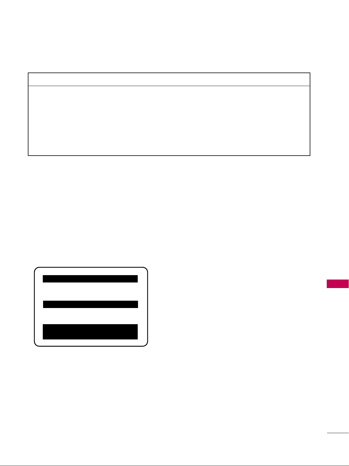
COMMERCIAL MODE SETUP
109
REFERENCE: CLONABLE MENU FEATURES
REFERENCE: CHECKING SOFTWARE VERSION
Procedure for Checking Software Version
The software version of the TV may be checked by accessing the INSTALLER MENU.
To do this, press the MENU button repeatedly until the menu display ceases to respond to menu key presses.
Then, press "9", "8", "7", "6", "ENTER/SELECT". Press Enter again to remove Installer menu.
Typical Installer Menu
000 INSTALLER SEQ 000
UPN 000-000-000-000 FPGA E0F1
PTC V1.00.000 CPU V3.06.00
HOSPITAL PTC INSTALLER MENU
■
NNoottee::
End user only has access to features that are available on End user pillow speaker, or remote control if
provided by the institution.
MMeennuu //SSuubb MMeennuu FFeeaattuurreess
CChhaannnneell MMeennuu
Auto Tuning
Manual Tuning
Channel Edit
Channel Label
OOppttiioonn MMeennuu
Language
Captions
PPiiccttuurree MMeennuu
Picture Mode
AAuuddiioo MMeennuu
Auto Volume
Clear Voice
IInnssttaalllleerr MMeennuu
Item Settings
Note: Some menu options will
revert to their default settings
after cloning.
Clonable Menu Features
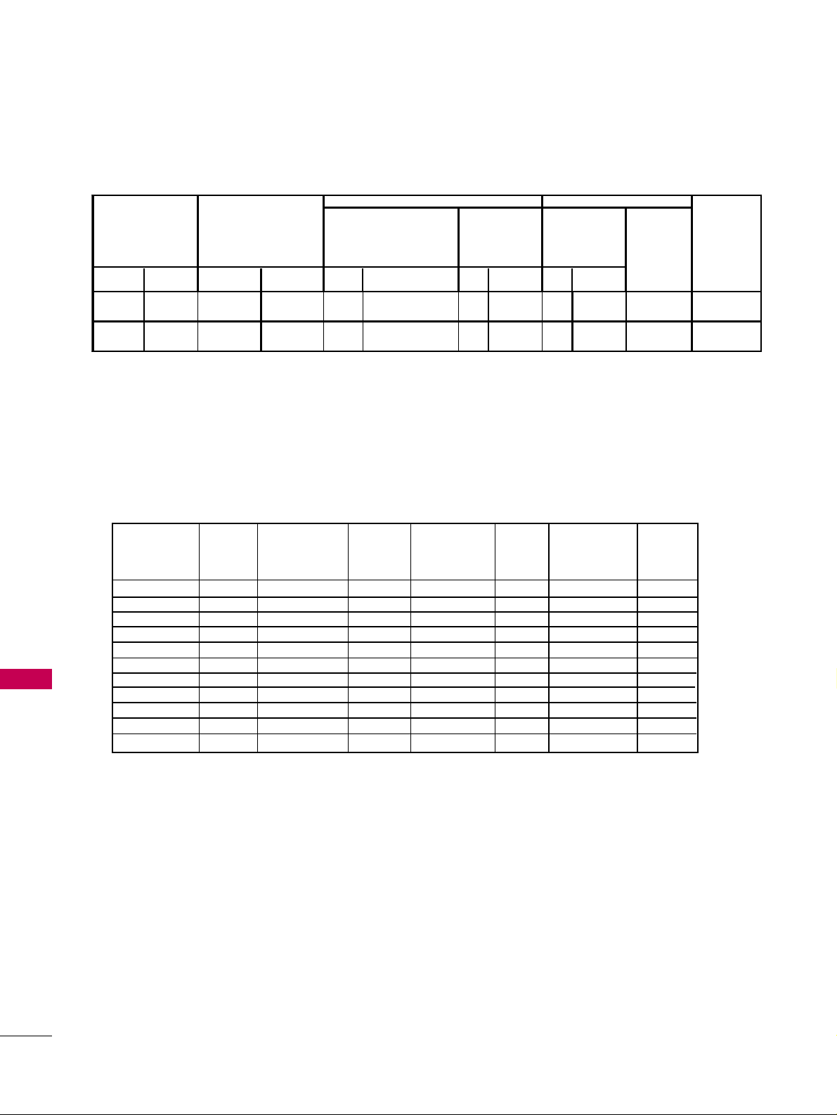
COMMERCIAL MODE SETUP
110
COMMERCIAL MODE SETUP
OLD_OCV
=0
OLD_OCV=
1
Source Input Source Mode Number Labeling Value Labeling Value Labeling
131 91 Video1 (Rear) CV/SVIDEO 39 REAR_AUX_EN 0x02
Rear Video
(Aux)
1
Rear Video
(Aux)
0 (VIDE0) 1
DTV 35 COMPPORT EN = 1 0x08
Front
Computer
3
Front
Computer
0 (VIDE0) 3
Installer Menu
TV
DIRECT ACCESS
Tuning
START AUX
SOURCE
ASSIGNMENT
DATA
STATUS
TYPE 0X0D
AUX SOURCE
(R)
ENABLE
MPI DATA
DATA STATUS
TYPE 0xD2
CURRENT AV
SOURCE (R)
MPI DATA
STATUS TYPE
0x41 SOURCES
ENABLED (R/W)
133 93 HDMI1/DVI
POWER SAVING SETUP
PPoowweerr SSaavviinnggss SSeettuupp
Installer Item 099 Backlighting: value set as shown below. (Default value is 200)
■
NNoottee::
Values are results of controlled experiments under laboratory conditions.
Item 099
Backlighting
(Static)
Item 099
Backlighting
(Dynamic)
Power
Savings
Rating
Power
Consumption
(Watts)
Brightness
10 0
90
80
70
60
50
40
30
20
10
1
150.4
133.7
12 2
10 7. 2
93.63
79.8
65.1
49.01
34.85
22.64
12.56
46.8
44.44
41.7
39.22
36.76
34.33
31.69
29.02
26.48
23.98
21.63
0.00%
5.04%
10.90%
16.20%
21.45%
26.65%
32.29%
37.99%
43.42%
48.76%
53.78%
200
19 0
18 0
17 0
16 0
150
14 0
130
120
110
101
67.39
62.28
56.1
49.15
43.07
36.3
30.03
25.16
19.7
14.73
10.51
32.71
31.57
30.4
29.22
28.11
26.9
25.69
24.75
23.46
22.24
21.32
30.11%
32.54%
35.04%
37.56%
39.94%
42.52%
45.11%
47.12%
49.87%
52.48%
54.44%
Brightness
Power
Savings
Rating
Power
Consumption
(Watts)
TV AUX INPUT CONFIGURATION
APPENDIX
111
APPENDIX
TROUBLESHOOTING
TThhee ooppeerraattiioonn ddooeess nnoott wwoorrkk nnoorrmmaallllyy..
TThhee vviiddeeoo ffuunnccttiioonn ddooeess nnoott wwoorrkk..
No picture &No sound
No or poor color
or poor picture
Poor reception on
some channels
Lines or streaks
in pictures
No picture
when connecting HDMI
Horizontal/vertical bars
or picture shaking
Picture appears slowly
after switching on
The remote control
doesn’t work
Power is suddenly
turned off
■
Check to see if there is any object between the product and the remote control
causing obstruction. Ensure you are pointing the remote control directly at the TV.
■
Ensure that the batteries are installed with correct polarity (+ to +, - to -).
■
Ensure that the correct remote operating mode is set: TV, VCR etc.
■
Install new batteries.
■
Is the sleep timer set?
■
Check the power control settings. Power interrupted.
■
Check whether the product is turned on.
■
Try another channel. The problem may be with the broadcast.
■
Is the power cord inserted into wall power outlet?
■
Check your antenna direction and/or location.
■
Test the wall power outlet, plug another product’s power cord into the outlet
where the product’s power cord was plugged in.
■
This is normal, the image is muted during the product startup process. Please
contact your service center, if the picture has not appeared after five minutes.
■
Adjust Color in menu option.
■
Try unplugging any others electronics that are near by to see if interference is
causing the problem.
■
Try another channel. The problem may be with the broadcast.
■
Are the video cables installed properly?
■
Activate any function to restore the brightness of the picture.
■
Check for local interference such as an electrical appliance or power tool.
■
Station or cable product experiencing problems, tune to another station.
■
Station signal is weak, reorient antenna.
■
Check for sources of possible interference.
■
Check antenna (Change the direction of the antenna).
■
Check HDMI cable over version 1.3.
If the HDMI cables don’t support HDMI version 1.3, it can cause flickers or no
screen display. In this case use the latest cables that support HDMI version 1.3.
APPENDIX
112
APPENDIX
TThheerree iiss aa pprroobblleemm iinn PPCC mmooddee.. ((OOnnllyy PPCC mmooddee aapppplliieedd))
■
Adjust resolution, horizontal frequency, or vertical frequency.
■
Check the input source.
■
Run the Auto configure or adjust clock, phase, or H/V position. (Option)
■
Check the signal cable.
■
Update video card drivers.
The signal is out of range
Screen color is unstable
or single color
Vertical bar or stripe on
background &
Horizontal Noise &
Incorrect position
TThhee aauuddiioo ffuunnccttiioonn ddooeess nnoott wwoorrkk..
*This feature is not available for all models.
Picture OK but No sound
Unusual sound from
inside the product
No sound
when connecting HDMI
or USB
No output from one
of the speakers
■
Press the VOL or VOLUME button.
■
Sound muted? Press the MUTE button.
■
Try another channel. The problem may be with the broadcast.
■
Are the audio cables installed properly?
■
Adjust Balance in menu option.
■
A change in ambient humidity or temperature may result in an unusual noise
when the product is turned on or off and does not indicate a fault with the
product.
■
Check HDMI cable over version 1.3.
■
Check USB cable over version 2.0.
EErrrraattiicc OOppeerraattiioonn
Installer menu setup
■
Adjust Installer menu settings as required.
PPoowweerr
No Power
■
See troubleshooting flow chart.
SSooffttwwaarree PPrroobblleemmss
Cannot direct enter chan-
nel number or “No Signal”
appears
■
After 2-5-5 + MENU, only channels included in TV controller will appear. If chan-
nel is available it can be added to channel scan, rescan channels. If it is not avail-
able, the ‘No Signal’ message appears on the TV screen.
■
NNoottee::
For other problems not caused by the TV, refer to other devices’ operating guides.
APPENDIX
113
REFERENCE: LT2002 CLONING PROCEDURE
TROUBLESHOOTING
32LG3DCH
(32LG3DCH-UA)
32LG3DC
(32LG3DC-UA)
Reset Clone After Static Shock
After replacing exhausted batteries, or if the programmer
behaves strangely after a static shock, use a paper clip or
similar instrument inserted through the small hole marked
”RESET” to activate the internal reset switch and restore
normal operation. After a reset, check the real-time clock
setting. It may be necessary to reset the Clone
Programmer clock from a TV containing the correct time.
Note
The LT2002 programmer is designed to be used with
TVs containing the 221-01006 and later processors. Use
with earlier TV sets may give unpredictable results.
Processors used before the 221-01006-04 have a limited
screen display capability. They cannot display entire
screens as shown in the quick setup instructions accom-
panying the LT2002 clone programmer. Use the printed
menu illustrations on the quick setup sheet supplied with
the Clone as an aid to making your programming choices.
(Although the menus are not all displayed, the clone
functions all operate normally.)
■
After cloning operations are complete, just unplug the LT2002 from the TV.
■
If the TV does not display a picture on the TV (blank screen) after a few seconds, just change channels.
Clone Programmer Troubleshooting
Warning: Do not use LT2002 while any PPV card is
installed in TV or clone programmer will be damaged.
CClloonnee PPrrooggrraammmmeerr
■
Press Reset on clone programmer, redo teach/learn. (Teach/Learn should take a
minimum of 1 minute.)
■
Only use an LG Installer remote to operate clone programmer with TV.
■
Connect M.P.I. cord properly, assure good connection.
■
TV must be powered On for clone to work.
■
Install 4 fresh AA high-quality alkaline batteries.
■
Connect TV to a reliable Analog channel signal source.
■
Set time on a TV, copy time to Clone Programmer.
■
Try a different LT2002 Clone programmer.
■
Reset Clone Programmer.
■
Retry cloning again.
Clone copies Setup in less
than 30 seconds
LED does not blink
Remote does not operate
clone
Clone menu hard to read
No time set
Clone not working
Clone Scans Channels
more than once
32LG3DCH
(32LG3DCH-UA)
32LG3DC
(32LG3DC-UA)
MMaasstteerr aanndd OOtthheerr TTVVss
■
Wait until procedure complete message is displayed.
■
Cloning is only possible with identical model TVs.
■
Reread cloning pages to be sure all tasks were performed.
■
Batteries must remain installed to retain time settings.
■
Disconnect newly-cloned TV from power for 5 seconds.
Cloning did not work
New Setup not present
Clone time disappeared

APPENDIX
114
APPENDIXAPPENDIX
CHANNEL BANKS SETUP TROUBLESHOOTING
CH 011-001 NORMAL-ADDED
Enter -> Change
CC ->VCHIP Menu Ch. Preview -> Exit
CHANNEL PREVIEW - BANK 1
Channel Banks Setup Menu
TThheerree iiss aa pprroobblleemm iinn CChhaannnneell..
■
Installer menu item 028 Ch Overide is set to 000.
Set Ch Overide to 001 to allow access for channel status change.
■
2-5-5+ Menu procedure was not performed.
Channel Banks setup menu will not be available until 2-5-5+ Menu procedure
is done. And, item 028 Ch Overide is set to 001 to allow access for channel
status changes.
■
Blanking a channel in one channel bank will make it blank in all channel banks.
■
Select a channel bank where the deleted channel number is set to ‘Normal
Added’. Direct enter the deleted channel number. Change to the bank you
want to activate the channel in. Select ‘Normal Added’ on the Ch Preview
Channel Banks menu.
■
TV is set up to display ‘Inactive TV’ message if all channels are ‘Normal
Delete’ in Channel Bank 4. Select another channel bank (Bank 1, 2 or 3)
which will return TV to normal operation.
■
Channel was deleted in currently selected channel bank. If banks were set up,
premium channels may only be available on another channel bank. Select the
channel bank where the channel is set to ‘Normal Added’. Or, direct enter chan-
nel number then go to banks menu and select ‘Normal Added’.
■
Item 027 Hospital Mode in Installer menu is set to 0. Set back to default ‘2’
for Channel Banks to appear with Bank or Source key presses.
Cannot change channel
status in menu.
Channel is blanked in all
channel banks.
Channel Preview menu
does not appear.
Cannot tune in deleted
channel on Ch Preview
menu.
‘Inactive TV’ message
appears and then TV
turns Off.
Channel found in scan
does not tune in with
Channel Up/Down.
If ‘Bank’ on Installer
remote is pressed, TV
shows Aux sources selec-
tion menu.

APPENDIX
115
TROUBLESHOOTING FLOW CHART
Controller
Quick
Check
Is
'STATUS'
LED on
Analog Board
Blinking
?
Plug
into AC
Power Outlet
Is
TV
Connected to
AC Power
?
Bad
TV
Yes
No
No
Yes
Is
Red LED
on TV
Lit
?
1. Bad Analog Board.
2. Bad Digital Board.
No
Cycle the power by removing
and re-connecting the AC
power cord. Observe the
'POWER' LED and TV screen
as soon as AC power is
re-applied.
Bad
TV
Did
Analog
Board 'POWER'
LED Turn On
Momentarily
?
No
Check to see if TV
is in Commercial Mode.
See Commercial Mode
Check chart.
Did TV
Turn On
Momentarily
?
No
Yes
Yes
Yes
Did
TV Turn
On
?
Yes
No
Press 'POWER' or 'ON/OFF'
key on TV
1. Bad TV
Press 'POWER' or 'ON/OFF'
or 'VOLUME UP/DOWN' or
'MUTE' key on Installer
Remote
Did
TV
Respond
?
No
1. Bad TV
2. Go to Remote
Control Checklist page 5
Yes
Press 'POWER' or 'ON/OFF'
or 'VOLUME UP/DOWN'
or 'MUTE' key on
User-Supplied Remote
Did
TV
Respond
?
No
1. Bad PPV Card
2. Go to Remote
Control Checklist page 5
Yes
End

APPENDIX
116
APPENDIX
COMMERCIAL MODE CHECK
Press the "On/Off" key
on the front panel.
The On/Off key is always operational.
Did
you get
a response
?
Bad TV
Yes
No
Did
TV stop
responding
or continue
to respond
?
TV is in
Commercial
Mode.
Stopped
responding
TV is not in Commercial Mode
Call Technical Support for
Assistance
Continued
to
respond
Leave
the
TV set On
Go to Installer menu
by pressing "MENU" until
the TV stops responding.

APPENDIX
117
GLOSSARY OF TERMS
77 55 OOHHMM RR FF CCAABBLL EE
The wire that comes from an off-air
antenna or cable service provider. The
end looks like a hex-shaped nut with a
wire sticking through the middle. It
screws onto the Antenna/Cable
threaded jack on the back of the TV.
330000 TTOO 7755 OOHHMM AADDAAPPTTEERR
A small device that connects a
two-wire 300 ohm antenna to a 75
ohm RF jack. They are usually about
an inch long with two screws on one
end and a round opening with a wire
sticking out on the other end.
AANNAALLOOGG TTEELLEEVVIISSIIOONN
Standard television broadcasting for-
mat in 4:3 picture aspect ratio.
AA//VV CCAABBLLEESS
Audio/Video cables. Three cables
bunched together—right audio
(red), left audio (white), and video
(yellow). A/V cables are used for
stereo playback of videocassettes
and for higher quality picture and
sound from other A/V devices.
AA//VV DDEEVVIICCEE
Any device that produces video or
sound (VCR, DVD, cable box, or tele-
vision).
AAMMPPLLIIFFIIEERR
An electronic device that amplifies
sound from a television, CD player,
VCR, DVD, or other Audio/Video
device.
AANNTTEENNNNAA
The physical receiver of television sig-
nals sent over the air. A large metal
piece of equipment does not always
have to be visible to be using an anten-
na.
CCAABBLLEE
Cable service box. Refers to the
descrambler box cable subscribers use
to receive cable programming signals.
CCAATTVV
Programming provided by a cable ser-
vice.
DDIIGGIITTAALL TTEELLEEVVIISSIIOONN
High-resolution, cinema-quality televi-
sion signals transmitted digitally.
DDVVII
Digital Video Interface
Accommodates analog and digital
interfaces with a single connector.
CCOOMMPPOOSSIITTEE VVIIDDEEOO
Typical video jack, uses one wire for
transporting three-color video signals.
CCOOMMPPOONNEENNTT VVIIDDEEOO
Uses three wires for transporting
three-color video signals. The end
result is usually better video quality.
DDEELLEETTEEDD
Lets you remove channels from the list
that the end user can scroll through
using CH (Channel) Up/Down.
HHDDMMII
High-definition multi-media interface.
HHDDTTVV
High-definition television. Refers to
television signals that have higher res-
olution than ordinary analog TV sig-
nals.
HHDDSSTTBB
High-definition set top box. Refers to
a tuner device that receives high-defi-
nition television signals which have
higher resolution than ordinary analog
TV signals.
IINN PPUU TT
Refers to the input jack that receives a
signal from a TV, VCR, DVD Player or
other Audio/Video device.
JJAA CC KK
An input or output connector on
the back of a TV, VCR, DVD Player
or other Audio/Video device.
MMOONNOO SSOOUUNNDD
Mono (monaural) sound is one chan-
nel of sound. On more than one
speaker, all the speakers play the same
audio.
OOUUTTPPUUTT
Refers to the output jack that sends a
signal out of a VCR, DVD, or other
A/V device.
PPHHYYSSIICCAALL CCHHAANNNNEELL NNUUMMBBEERR
See Note 1.
RRGGBB ((RReedd,, GGrreeeenn,, BBlluuee))
Connection input or output port
available for producing a video image
using three separate colors: Red,
Green, and Blue.
RRSS--223322CC
Serial communication port through
which the display panel is controlled.
22 NN DD AA UU DD II OO
PPRR OO GG RR AA MM MM II NN GG // SSAA PP
Second Audio Programming (SAP) is
another, separate audio channel
available with some programming.
Choosing SAP often refers to listen-
ing to audio in another language,
such as Spanish or French.
SSiiggnnaall
Picture and sound traveling through a
cable, or over the air, to the TV.
SStteerreeoo ssoouunndd
Stereo (Stereophonic) sound refers to
audio that’s divided into right and
left sides.
TTuunneerr
Device that picks up the broadcast sig-
nal and turns it into picture and
sound.
vviirrttuuaall CChhaannnneell nnuummbbeerr
See Note 1.
XXDDSS
Extended Data Service: Additional pro-
gram information included on the
signal provided at the discretion of
the broadcaster.
Note 1
Refer to www.atsc.org for further
information.
A list of definitions for some of the words found in this guide

APPENDIX
118
APPENDIX
MAINTENANCE
Early malfunctions can be prevented. Careful and regular cleaning can extend the amount of time you can
enjoy your new TV.
Caution: Be sure to turn the power off and unplug the power cord before you begin any cleaning.
Cleaning the Screen
Here’s a great way to keep the dust off your screen for a while. Wet a soft cloth in a mixture of lukewarm
water and a little fabric softener or dish washing detergent. Wring the cloth until it’s almost dry, and then
use it to wipe the screen.
Make sure the excess water is off the screen, and then let it air-dry before you turn on your TV.
GG
If you expect to leave your TV dormant for a long time (such as a vacation), it’s a good idea to unplug
the power cord to protect against possible damage from lightning or power surges.
CAUTION
2
1
GG
Do not use window/glass cleaner or anything with ammonia to clean the screen.
WARNING
Cleaning the Cabinet
■
To remove dirt or dust, wipe the cabinet with a soft, dry, lint-free cloth.
■
Please be sure not to use a wet cloth.
Extended Absence
APPENDIX
119
PRODUCT SPECIFICATIONS
■
The specifications shown above may be changed without prior notice for quality improvement.
MODEL
NTSC-M, VSB, 64 & 256 QAM
VHF 2-13, UHF 14-69, CATV 1-135, DTV 2-69, CADTV 1-135
75 ohm
32 ~ 104°F (0 ~ 40°C)
Less than 80%
-4 ~ 140°F (-20 ~ 60°C)
Less than 85%
Dimensions
(Width
x Height
x Depth)
Weight
Power requirement
Television System
Program Coverage
External Antenna Impedance
Environment
condition
With stand
Without stand
With stand
Without stand
Operating Temperature
Operating Humidity
Storage Temperature
Storage Humidity
26LG3DCH
(26LG3DCH-UA)
26.1 x 17.6 x 3.1 inches
663.3 x 449.8 x 80.0 mm
18.9 pounds / 8.6 kg
AC120V ~ 50/60Hz
22LG3DCH
(22LG3DCH-UA)
20.7 x 15.2 x 3.2 inches
528 x 387.3 x 82.7 mm
13.6 pounds / 6.2kg
AC120V ~ 50/60Hz
31.5 x 21.4 x 4.2 inches
801.8 x 544.4 x 109 mm
26.2 pounds / 11.9 kg
AC120V ~ 50/60Hz
31.5 x 23.7 x 9.1 inches
801.8 x 604.2 x 232 mm
31.5 x 21.4 x 4.2 inches
801.8 x 544.4 x 109 mm
29.5 pounds / 13.4 kg
26.2 pounds / 11.9 kg
AC100-240V ~ 50/60Hz
32LG3DCH
(32LG3DCH-UA)
32LG3DC
(32LG3DC-UA)
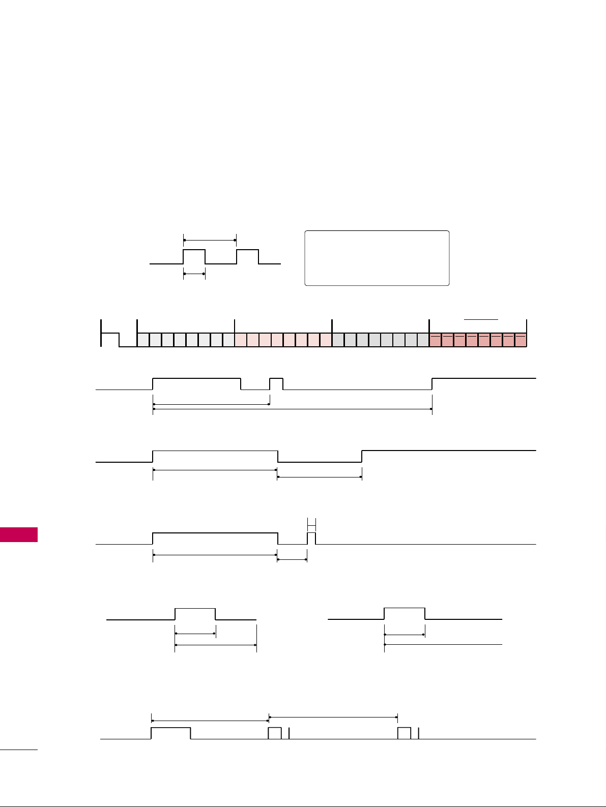
APPENDIX
120
APPENDIX
IR CODES
■
Configuration of frame
1st frame
Repeat frame
■
Lead code
■
Repeat code
■
BBiitt ddeessccrriippttiioonn
■
FFrraammee iinntteerrvvaall:: TTff
The waveform is transmitted as long as a key is depressed.
C0 C1 C2 C3 C4 C5 C6 C7 C0 C1 C2 C3 C4 C5 C6 C7 D0 D1 D2 D3 D4 D5 D6 D7 D0 D1 D2 D3 D4 D5 D6 D7
Lead code Low custom code High custom code Data code Data code
Repeat code
Tf
4.5 ms
9 ms
2.25 ms
9 ms
0.55 ms
0.56 ms
1.12 ms
0.56 ms
2.24 ms
Tf Tf
Tf=108ms @455KHz
Bit ”0”
Bit ”1”
1. How to Connect
■
Connect your wired remote control to the Remote Control port on the TV.
2. Remote Control IR Codes
■
Output waveform
Single pulse, modulated with 37.917KHz signal at 455KHz
T1
Tc
Carrier frequency
FCAR = 1/TC = fOSC/12
Duty ratio = T1/TC = 1/3
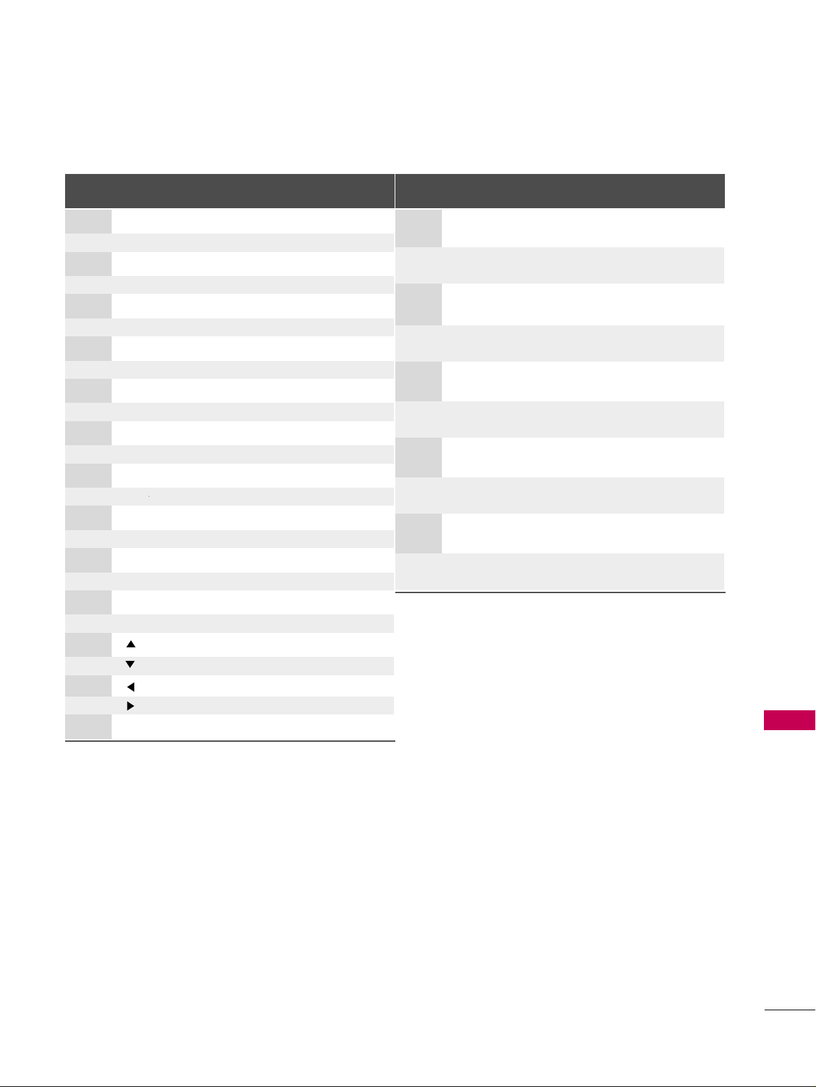
APPENDIX
121
Code
Function Note
(Hexa)
08 POWER
Remote control Button (Power On/Off)
0F TV
Remote control Button
0B INPUT Remote control Button
4D PICTURE Remote control Button
52 SOUND Remote control Button
0A SAP Remote control Button
79 RATIO Remote control Button
10-19 Number Key 0-9 Remote control Button
4C - (Dash) Remote control Button
1A FLASHBK Remote control Button
02 VOL + Remote control Button
03 VOL - Remote control Button
00 CH + Remote control Button
01 CH - Remote control Button
0E TIMER Remote control Button
39 CC Remote control Button
09 MUTE Remote control Button
CB ADJUST Remote control Button
43 MENU Remote control Button
5B RETURN Remote control Button
40 Remote control Button
41 Remote control Button
07 Remote control Button
06 Remote control Button
44 ENTER Remote control Button
Code
Function Note
(Hexa)
D6 TV Discrete IR Code
(TV Input Selection)
5A AV1
Discrete IR Code
(AV1 Input Selection)
BF COMPONENT
Discrete IR Code
(
COMPONENT
Input Selection)
D5 RGB
Discrete IR Code
(
RGB
Input Selection)
CE HDMI1
Discrete IR Code
(
HDMI1
Input Selection)
76 Ratio 4:3
Discrete IR Code
(
Only 4:3 Mode
)
77 Ratio 16:9
Discrete IR Code
(
Only 16:9 Mode
)
AF Ratio Zoom
Discrete IR Code
(
Only Zoom1 Mode
)
C4 POWER ON
Discrete IR Code
(
Only Power On
)
C5 POWER OFF
Discrete IR Code
(
Only Power Off)