Loading ...
Loading ...
Loading ...
Name of each Part
Installation manual 7
ڸ
ڹ
ں
ڻ
ڼڽ
ۀ
ڿ
ھ
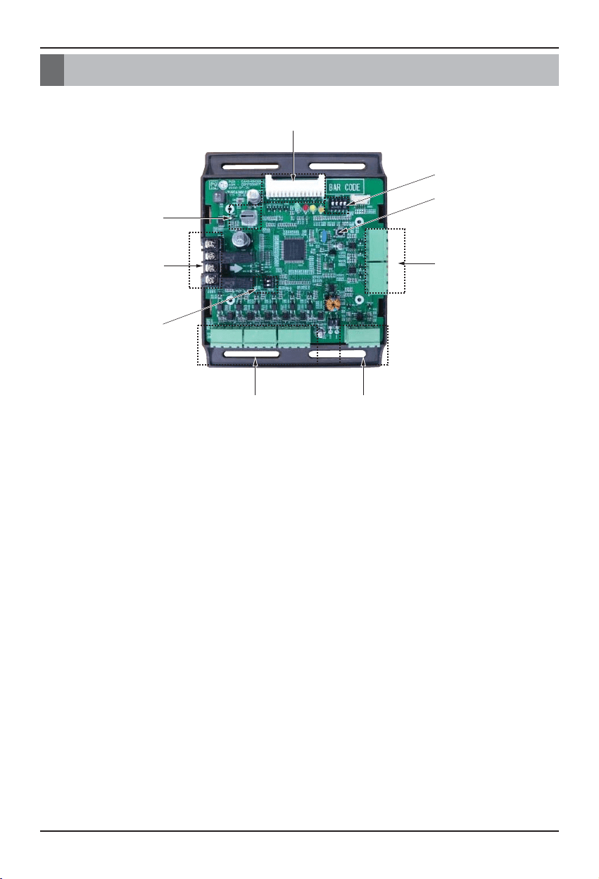
Name of each Part
① Main connector : Power input and communication connector with Outdoor unit
② SW104 : Rotary Switch for setting Demand control step
③ Digital Output : Operating & Error status Relay output (250V, 1A)
④ SW102 : Switch for setting internal function
⑤ Digital Input : Dry contact input
⑥ Analog Input : DC0~10V Analog signal input
⑦ Analog Output : DC0~10V Analog signal output
⑧ SW103 : Reset Switch
⑨ SW101 : Dip Switch for setting operating function
Loading ...
Loading ...
Loading ...