McIntosh Laboratory, Inc. 2 Chambers Street Binghamton, New York 13903-2699 Phone: 607-723-3512 www.mcintoshlabs.com
MA12000
Integrated Amplifier
Owner’s Manual
2
Thank you from all of us at
McIntosh
With the MA12000 Intergrated Amplier, you have
invested in a precision instrument that will provide
you with many years of enjoyment. Please take a few
moments to familiarize yourself with the features and
instructions to get the maximum performance from
your equipment.
If you need further technical assistance, please contact
your dealer who may be more familiar with your
particular setup including other brands. You can also
contact McIntosh with additional questions or in the
unlikely event of needing service.
McIntosh Laboratory, Inc.
2 Chambers Street
Binghamton, New York 13903
Technical Assistance: (607) 723-3512
Customer Service: (607) 723-3515
Fax: (607) 724-0549
Email: [email protected]
Website: mcintoshlabs.com
Copyright 2020 © by McIntosh Laboratory, Inc.
Important Safety Information is supplied in a separate document “Important Additional Operation Information Guide”
Make a Note
For future reference, you can jot down your serial
number and purchase information here. We can
identify your purchase from this information if the
occasion should arise.
Serial Number:
Purchase Date:
Dealer Name

3
Trademark and License
Informaon
The McIntosh MA12000 incorporates copyright
protected technology that is protected by U.S. patents
and other intellectual property rights. The MA12000
uses the following Technologies:
Trademark License Information
ASIO is a trademark and
software of Steinberg Media
Technologies GmbH
Manufactured under license
from Dolby Laboratories.
Dolby, Dolby Audio, and
the double-D symbol
are trademarks of Dolby
Laboratories.
For DTS patents, see http://
patents.dts.com. Manufactured
under license from DTS, Inc.
DTS, the Symbol, DTS and
the Symbol together, and
Digital Surround are registered
trademarks and/or trademarks
of DTS, Inc. in the United
States and/or other countries.
DTS, Inc. All Rights Reserved.
The terms HDMI, HDMI
High-Definition Multimedia
Interface, and the HDMI Logo
are trademarks or registered
trademarks of HDMI Licensing
Administrator, Inc.
HIGH-DEFINITION MULTIMEDIA INTERFACE
TM
Table of Contents
Thank you from all of us at McIntosh .................... 2
Make a Note ............................................................ 2
Trademark and License Information ...................... 3
General Information ............................................... 4
Connector and Cable Information ......................... 4
Introduction ............................................................ 5
Performance Features ............................................. 5
Dimensions ............................................................. 6
Installation .............................................................. 7
Rear Panel Connections .......................................... 8
Making Connections .............................................. 9
Phono/Unbalanced Inputs .................................. 9
Balanced/XLR Input and Output ...................... 9
RS232 ................................................................. 9
Wired IR Input ................................................... 9
Power Control (Trigger) Outputs ..................... 10
Passthru............................................................ 10
Data Out ........................................................... 10
Headphones .......................................................11
HDMI (ARC) and CEC ....................................11
Lip Sync Mode (ARC) ......................................11
HDMI and Optical Gain ...................................11
USB .................................................................. 12
Optical.............................................................. 12
Coax ................................................................. 12
MCT ................................................................. 12
Passthru Example ................................................. 13
Connecting for Bi-Amplification...........................14
How to use the Remote Control .............................16
Remote Control Diagram ......................................17
Trim Functions and Settings ..................................18
How to Operate the Setup Mode .......................... 20
Default Settings ............................................... 20
Firmware Version ............................................ 20
Input Settings ................................................... 20
Output Settings ................................................ 22
Power Control Triggers 1 and 2 ....................... 23
Data Ports ....................................................... 23
Passthru............................................................ 24
Comm Port Baud Rate ..................................... 24
Remote Control Codes ..................................... 25
IR Sensor ......................................................... 25
Power Mode ..................................................... 25
Factory Reset ................................................... 26
Reset of Microprocessors................................. 26
How to Operate the MA12000 ........................ 27
Preamplifier Specifications ............................. 33
Digital Audio Specifications ........................... 34
General Specifications ..................................... 34
Packing Instructions ........................................ 35

4
Passthru Outputs.
Data Port Connectors
The Data Out Ports send Remote Control Signals
to Source Components. A 3.5mm
stereo mini phone plug is used for
connection.
IR IN Port Connectors
The IR IN Port also uses a 3.5mm
stereo mini phone plug and allows
the connection of other brand IR
Receivers to the MA12000.
RS232-C Data Port Cable
The RS232 Data Cable is a 3.5mm
stereo mini phone plug to a sub miniature DB 9
connector:
Binding Connector
When cables with spade lugs are used for Loudspeaker
Connection, the spade lugs need an
opening of at least 3/10 inch (7.6mm)
McIntosh Plug-In Jumper Connector
The MA12000 utilizes two phono
style Plug-In Jumpers to connect the
Preamplifier Output to the Power
Amplifier Input.
Note: The Jumper Connector is available from the
McIntosh Parts Department:
McIntosh Jumper Connector
Part No. 11808000
Connector and Cable Informaon
XLR Connectors
Below is the Pin configuration for the XLR Balanced
Connectors on the MA12000. Refer to the diagram for
connection:
PIN 1: Shield/Ground
PIN 2: + Output
PIN 3: - Output
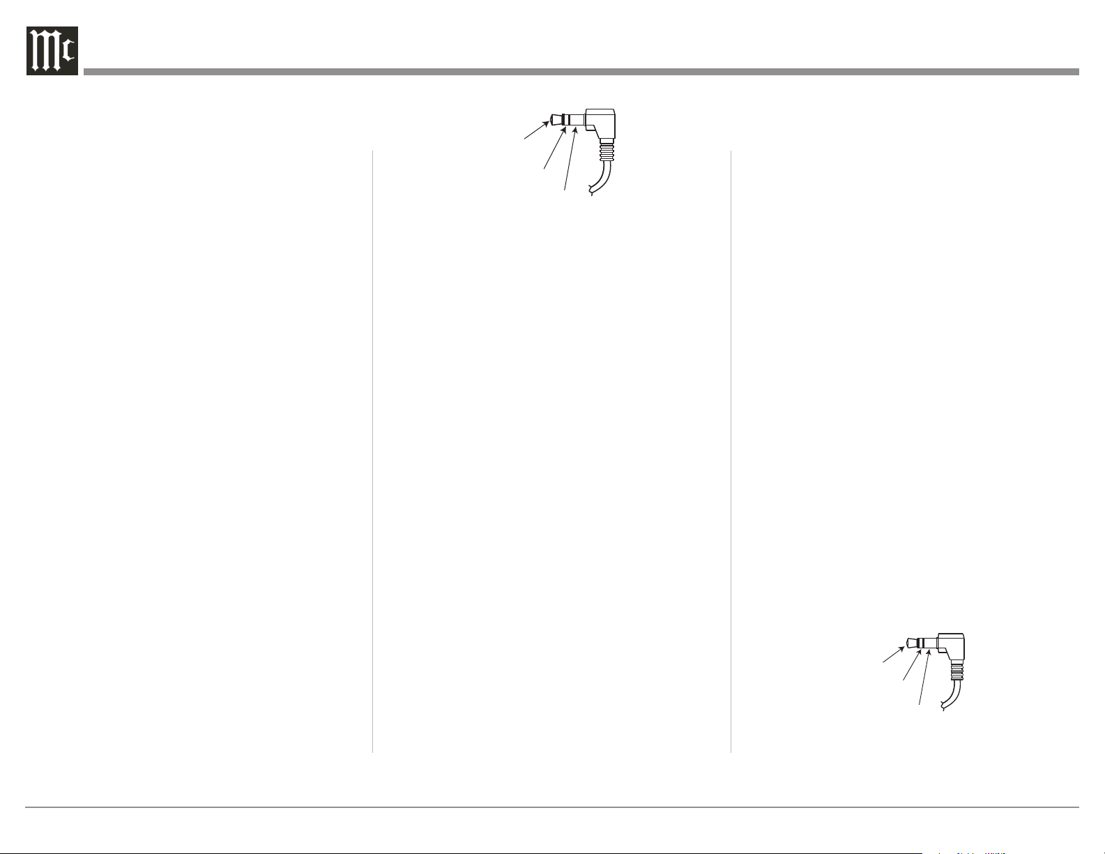
Power Control and Trigger Connectors
The Power Control Trigger Output Jacks send and
Passthru Input Jack receives Power On/Off Signals
(+12 volt/0 volt) when connected to other McIntosh
Components. An additional
connection is for controlling the
illumination of the Power Output
Meters on McIntosh Power
Amplifiers. A 3.5mm stereo mini
phone plug is used for connection
to the Power Control, Trigger and
General Informaon
1. For additional connection information, refer to the
owner’s manual(s) for any component(s) connected
to the MA12000.
2. Apply AC Power to the MA12000 and other
McIntosh Components only after all the system
components are connected together. Failure to do
so may cause a malfunction of system operations
as the Microprocessor’s Circuitry inside the
components is active when AC Power is applied.
3. The MA12000 includes a Power Mode Auto Off
Feature and the default setting is enabled. For
additional information including how to disable it,
refer to page 25.
4. When Power Amplifier Protection Circuitry of the
MA12000 has activated, the LEDs under the Tubes
illuminate the Tubes amber to alert you.
5. When the Power Transformer has overheated
due to improper ventilation and/or high ambient
operating temperature, AC Power is removed from
the MA12000. Normal operation will resume when
the operating temperature is in a safe range again.
6. For the best performance and safety, it is important
to always match the impedance of the Loudspeaker
to the Power Amplifier connections.
Note: The impedance of a Loudspeaker actually varies as
the Loudspeaker reproduces different frequencies. As a
result, the nominal impedance rating of the Loudspeaker
(usually measured at a midrange frequency) might not
always agree with the impedance of the Loudspeaker
at low frequencies where the greatest amount of power
is required. Contact the Loudspeaker Manufacturer for
additional information about the actual impedance of
the Loudspeaker before connecting it to the McIntosh
MA12000.
7. The MA12000 Remote Control is capable of
operating other components. For additional
information go to www.mcintoshlabs.com.
8. The IR Input, with a 1/8 inch mini phone jack, is
configured for non-McIntosh IR sensors such as
a Xantech Model DL85K Kit. Use a Connection
Block such as a Xantech Model ZC21 when two
or more IR sensors need to be connected to the
MA12000. The signal from a connected External
IR Sensor will have priority over the signal from
the Front Panel IR Sensor.
9. When discarding the unit, comply with local
rules or regulations. Batteries should
never be thrown away or incinerated but
disposed of in accordance with the local
regulations concerning battery disposal.
10. For additional information on the
MA12000 and other McIntosh Products please visit
the McIntosh Web Site at www.mcintoshlabs.com.
Data
Signal
N/C
Data
Ground
Power
Control
Meter
Illumination
Control
Ground
Main, Trig 1&2
and Pass-Thru
IR Data
Control
Ground
N/C
PIN 1
PIN 6
PIN 5
PIN 9
Data In
(DB9-pin2)
Ground
(DB9-pin5)
Data Out
(DB9-pin3)
DB9
(male connector)
3/10 of an inch
(7.6millimeters)
PIN 2 PIN 1
PIN 3
PIN 1
PIN 2
PIN 3

5
Introducon
Now you can take advantage of traditional McIntosh
standards of excellence in the MA12000 Integrated
Amplier. The Power Amplier section of the
MA12000, with a power output of 350 watts per
channel, will drive a pair of quality Loudspeakers to a
high level of performance.
The exible Preamplier section features four AX7A
Tubes and provides connections for various input
sources and may also be used to drive an external
Power Amplier(s).
The MA12000 reproduction is sonically transparent
and absolutely accurate. The McIntosh Sound is “The
Sound of the Music Itself.”
Performance Features
• Power Output with Patented Autoformer
The MA12000 consists of a 350 watts per channel
Power Amplifier with less than 0.005% distortion.
The McIntosh designed and manufactured Autoformer
allows connection of 2, 4 or 8 ohm Loudspeakers.
The Power Amplifier uses ThermalTrak™
1
Output
Transistors to minimize distortion and operating
temperature.
• Sentry Monitor and Thermal Protection
McIntosh Sentry Monitor power output stage
protection circuits ensure the MA12000 will have a
long and trouble free operating life. Built-in Thermal
Protection Circuits guard against overheating.
• Power Guard
The patented McIntosh Power Guard circuit prevents
amplifier clipping and protects your valuable
Loudspeakers. Tubes will glow amber when engaged.
1
ThermalTrak™ and ON Semiconductor are trademarks of
Semiconductor Components Industries, LLC
• Electronic Switching and Balanced Connections
The Preamplifier uses Logic Controlled
Electromagnetic Switches on all inputs and operating
functions for reliable, noiseless, signal switching.
There is a Balanced Input for connection of a source
component.
• Digital Audio Inputs
The Digital Inputs decode PCM and DSD Signals
from external sources. Coaxial, Optical and HMDI
Inputs process Digital Signals up to 192kHz with
24-Bit resolution. The Digital MCT Input Circuitry
directly decodes SACD/CD signals from an external
Transport component. The USB Input Port can
process streaming audio with 32-bit resolution up to
384kHz sampling rate. The Input Port can also process
DSD512 as well as DXD 24-bit signals up to the same
384kHz sampling rate.
• Moving Coil and Moving Magnet Phono Inputs
The MA12000 has two precision Phono Preamplifier
Circuits for Moving Coil and Moving Magnet Phono
Cartridges. Both circuits use the latest designs to
provide the lowest possible noise, distortion and
flat frequency response. The MC and MM Phono
Cartridge Inputs have selectable loading.
• Eight Band Equalizer
The Equalizer Controls provide ±12dB signal gain at
center frequencies of 25, 50, 100, 200, 400, 1kHz,
2.5kHz and 10kHz. There is also an Equalizer Bypass
Mode to remove the Equalizer from the Signal Path of
any selected input.
• Multifunction Display and Power Meters
The Front Panel Display indicates source selection,
volume levels and setup functions. The Illuminated
Power Output Meters are peak responding, and
indicate the power output of the amplifier.
• Power Control Output and Trigger Assignment
A Power Control connection for convenient Turn-On
of McIntosh Power Amplifiers, Source Components
and Accessories is included. The Power Control
Trigger Ouputs may be assigned to activate when a
given Input/Output is selected.
• PassThru Mode
The Automatic PassThru Mode allows the MA12000
to become part of a Multichannel Sound System for
DVD-Audio, SACD and Home Theater Movies.
• Remote Control
The Data Ports together with the supplied Remote
Control provide control of McIntosh Source
Components connected to the MA12000.
• Special Power Supply
The large Power Transformer, multiple filter
capacitors with 280 Joules of Energy Storage and
regulated Power Supply, ensures stable noise free
operation even if the AC power line fluctuates.
• Solid Cinch™ Speaker Binding Posts
McIntosh Patented gold plated Binding Post deliver
high current output. They securely accept large
diameter wire and spade lugs. Banana plugs may also
be used but only in the United States and Canada.
• Glass Front Panel and Super Mirror Chassis
Finish
The famous McIntosh Illuminated Glass Front Panel
uses long life Light Emitting Diodes (LEDs) and the
Stainless Steel Chassis with Super Mirror Finish
ensures that the MA12000 will retain its pristine
beauty for many years.
6
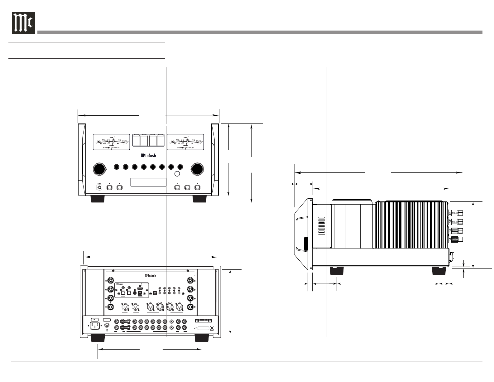
Dimensions
The following dimensions can assist in determining
the best location for your MA12000. There is
additional information on the next page pertaining to
installing the MA12000 into cabinets.
Side View of the MA12000
3/16"
0.5cm
7/8"
2.2cm
19-3/4"
50.2cm
16-7/16"
41.8cm
8-1/4"
21.0cm
2-1/4"
5.7cm
12-3/4"
32.4cm
1-1/4"
3.2cm
17-1/2"
44.5cm
16-13/16"
42.7cm
7-15/16"
20.2cm
11-1/2"
29.2cm
8-13/16"
22.4cm
9-7/16"
24.0cm
USB 35%
DSD256
HEAD PHONE
1
2OUTP UTS EQUA LIZER
MUTE
STANDB Y/ON
RESE T
PUSH - TR IM
HOLD - SE TUP
TRIM / SE TUP
ADJUS T
25
VOLU ME
I P T
50
100 200 400 1k 2.5 k 10k
PUSH - TR IM
HOLD - SE TUP
N U
M A 1 2 0 0 0
I N T E G R A T E D A M P L I F I E R
PU SH PU S H PUS H
PU SH
FUSE
PUSH
MA1 200 0 INT EGRATED AM PLI FIER
McINTOSH LABORATORY, INC., BINGHAMTON, NY
HANDCRAFTED IN USA WITH US AND IMPORTED PARTS
R OUTPUT
8Ω
4Ω
2Ω
CLASS 2 WIRING
R
L
OUTPUT 2
BALANCED INPUTS
2R 2L 1R
1L
L OUTPUT
8Ω
4Ω
2Ω
CLASS 2 WIRING
DATA PORTS
3
1
4
2
IR IN
RS232
EXT
CTRL
POWER CONTROL
OUTPUTS
MAIN
TRIG 1
PASSTHRU
INPUT
TRIG 2
SERVICE
PORT
120V 50/60Hz
6.6A
T 10AH 250V
FIXED 1 PWR AMP 1
2
OUTPUTS
UNBALANCED INPUTS
3 4 5 6
L
R
LRGND
CAUTION
RISK OF ELECTRIC SHOCK
DO NOT OPEN
SERIAL
NUMBER
L
R
GND
MC
MM
PHONO
ATTENTION: RISQUE DE CHOC ELECTRIQUE-NE PAS OUVRIR
USB AUDIO
DA2 DIGITAL AUDIO MODULE
HDMI (ARC)
COAX 2
COAX 1
MCT
OPTICAL 2OPTICAL 1
DIGITAL AUDIO INPUTS
SERIAL
NUMBER
Front View of the MA12000
Rear View of the MA12000
35
35 0
3.5
.35
P O W E R O U T P U T
- 50
- 30
DE CI BEL S
WAT TS
- 40
-2 0
-10
0
3.5
m
35
m
7
0
0
35
35 0
3.5
.35
P O W E R O U T P U T
- 50
- 30
DE CI BEL S
WAT TS
- 40
-2 0
-10
0
3.5
m
35
m
7
0
0
7
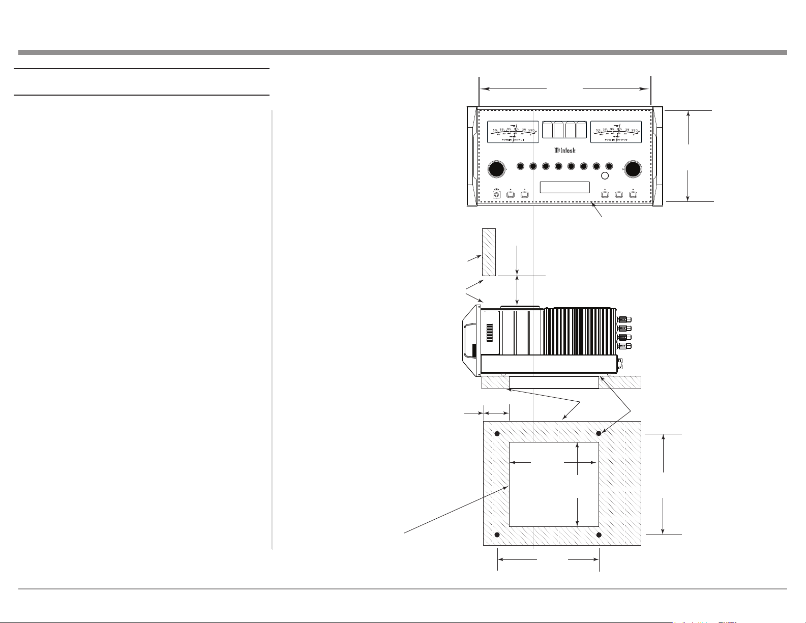
Installaon
The MA12000 can be placed upright on a table or
shelf, standing on its four feet. It also can be custom
installed in a piece of furniture or cabinet of your
choice. The four feet may be removed from the
MA12000 when it is custom installed as outlined
below. The four feet, together with the mounting
screws, should be retained for possible future use if
the MA12000 is removed from the custom installation
and used free standing. The required panel cutout,
ventilation cutout and unit dimensions are shown.
Always provide adequate ventilation for your
MA12000. Cool operation ensures the longest possible
operating life for any electronic instrument. Do not
install the MA12000 directly above a heat generating
component such as a high powered amplier. If all
the components are installed in a single cabinet, a
quiet running ventilation fan can be a denite asset in
maintaining all the system components at the coolest
possible operating temperature.
A custom cabinet installation should provide the
following minimum spacing dimensions for cool
operation.
Allow at least 6 inches (15.24cm) above the top,
2 inches (5.08cm) below the bottom and 2 inches
(5.1cm) on each side of the Integrated Amplier,
so that airow is not obstructed. Allow 20 inches
(50.8cm) depth behind the front panel. Allow 1-7/6
inch (3.66cm) in front of the mounting panel for knob
clearance. Be sure to cut out a ventilation hole in the
mounting shelf according to the dimensions in the
drawing.
USB 35%
DSD256
HEADP HONE
1
2OUTPU TS EQUAL IZER
MUTE
STANDBY /ON
RESET
PUSH - TR IM
HOLD - SE TUP
TRIM / SE TUP
ADJUS T
25
VOLU ME
I P T
50
100 200 400 1k 2 .5k 10k
PUSH - TR IM
HOLD - SE TUP
N U
M A 1 2 0 0 0
I N T E G R A T E D A M P L I F I E R
8-5/16"
21.1cm
17-1/16"
43.3cm
Cutout Opening for Custom Mounting
MA12000 Front Panel
Custom Cabinet Cutout
Cutout
Opening
for
Ventilation
Cutout Opening for Ventilation
Support
Shelf
Cabinet
Front
Panel
Chassis
Spacers
MA12000 Side View
in Custom Cabinet
MA12000 Bottom View
in Custom Cabinet
9-1/2"
24.1cm
6"
15.2cm
Opening
for Ventilation
16"
40.6cm
11-1/2"
29.2cm
Note: Center the cutout Horizontally
on the unit. For purposes of
clarity, the above illustration
is not drawn to scale.
10"
25.4cm
4-5/8"
11.8cm
35
35 0
3.5
.
35
P O W E R O U T P U T
- 50
- 30
DE CIB EL S
WAT TS
- 40
-2 0
-10
0
3.5
m
35
m
7
0
0
35
35 0
3.5
.
35
P O W E R O U T P U T
- 50
- 30
DE CIB EL S
WAT TS
- 40
-2 0
-10
0
3.5
m
35
m
7
0
0
8
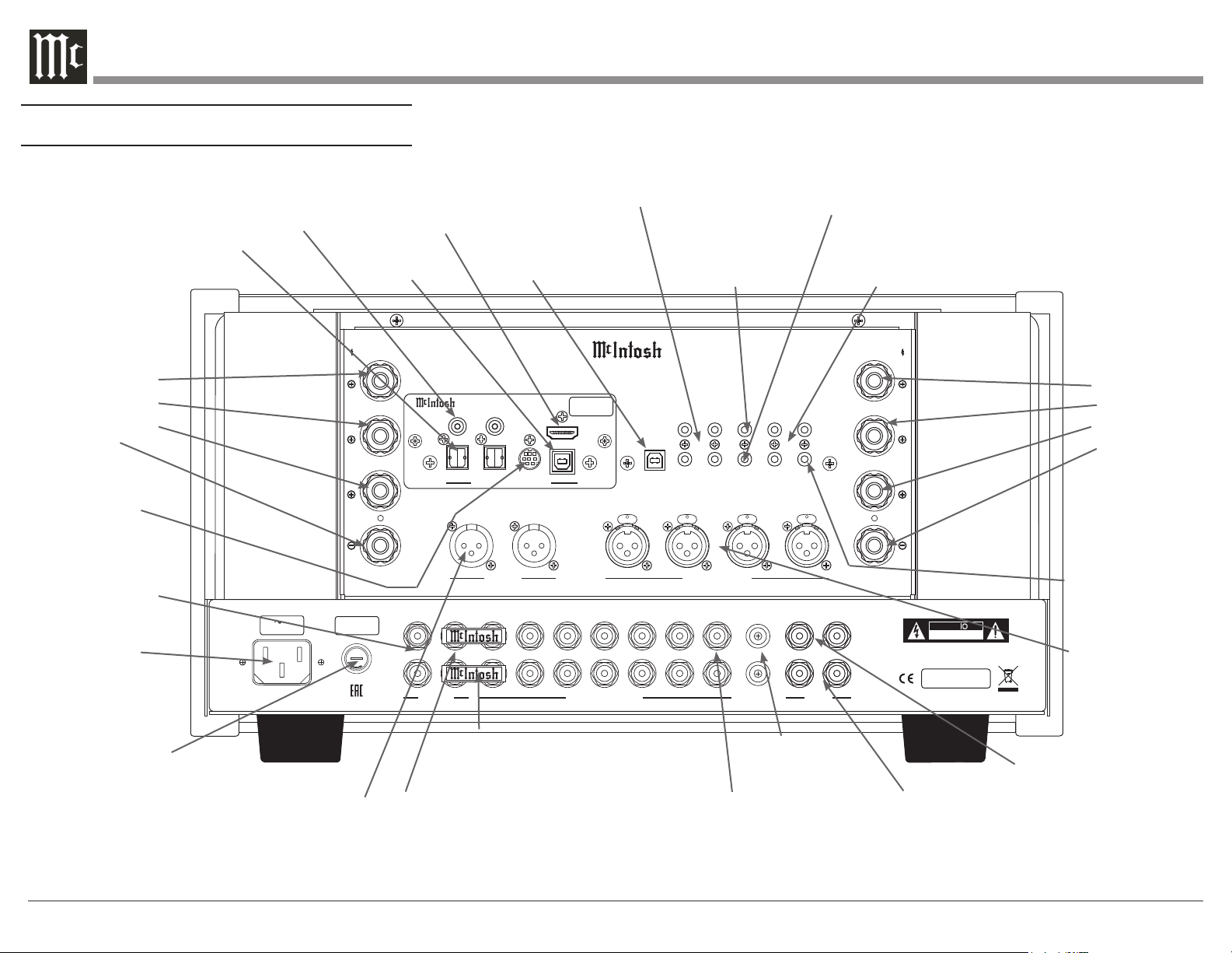
Rear Panel Connecons
P U S H P U S H P U SH
P U S H
FUSE
PUSH
MA12000 INTEGRATED AMPLIFIER
McINTOSH LABORATORY, INC., BINGHAMTON, NY
HANDCRAFTED IN USA WITH US AND IMPORTED PARTS
R OUTPUT
8Ω
4Ω
2Ω
CLASS 2 WIRING
R
L
OUTPUT 2
BALANCED INPUTS
2R 2L 1R
1L
L OUTPUT
8Ω
4Ω
2Ω
CLASS 2 WIRING
DATA PORTS
3
1
4
2
IR IN
RS232
EXT
CTRL
POWER CONTROL
OUTPUTS
MAIN
TRIG 1
PASSTHRU
INPUT
TRIG 2
SERVICE
PORT
120V 50/60Hz
6.6A
T 10AH 250V
FIXED 1 PWR AMP 1
2
OUTPUTS
UNBALANCED INPUTS
3 4 5 6
L
R
LRGND
CAUTION
RISK OF ELECTRIC SHOCK
DO NOT OPEN
SERIAL
NUMBER
L
R
GND
MC
MM
PHONO
ATTENTION: RISQUE DE CHOC ELECTRIQUE-NE PAS OUVRIR
USB AUDIO
DA2 DIGITAL AUDIO MODULE
HDMI (ARC)
COAX 2
COAX 1
MCT
OPTICAL 2OPTICAL 1
DIGITAL AUDIO INPUTS
SERIAL
NUMBER
DATA PORTS (4) send signals to
Source Components to allow control
with the MA12000 Remote Control
SERVICE PORT for
service use only
IR INput for signals
from a compatible IR
Room Sensor
RS232 connector for
connection to a computer or
other control device
POWER CONTROL OUTPUTS
(Triggers) send power On/Off signals
to a McIntosh Component when the
MA12000 is switched On/Off
Left Loudspeaker
Binding Posts:
Positive 8 Ohm
Positive 4 Ohm
Positive 2 Ohm
Negative
Right Loudspeaker
Binding Posts:
Positive 8 Ohm
Positive 4 Ohm
Positive 2 Ohm
Negative
AC Power
Connector
Main Fuse holder,
refer to the back panel
of your MA12000 to
determine the correct
fuse size and consult the
Important Additional
Operation Information
Guide for more
information
FIXED OUTPUTS can
send signals to the input
of a recording device
OUTPUTS 1 sends signals to a
Power Amplier and is switched
On/Off with the Front Panel
Output 1 Push-Button or Remote
Control
JUMPER PLUGS connect the Preamplier
OUT-PUT 1 Jacks to the PWR AMP INPUTS
Jacks and are required for normal operation
UNBALANCED
INPUTS 1 thru 6
accept high level
program source signals
GND terminals
accepts ground wire
from a turntable
PHONO MM accepts
signals from a Moving
Magnet Phono
Cartridge
PHONO MC
accepts the low
level signals from
a Moving Coil
Phono Cartridge
BALANCED
INPUTS
1 and 2 accept
high level program
source signals
PASSTHRU Input
receives turn On/Off
signals from an Audio/
Video Processor
HDMI (ARC)
Input
USB Audio
Input Type B
COAX 1 & 2
Digital Coaxial
Inputs
OPTICAL 1 & 2
Digital Inputs
MCT McIntosh
Proprietary digital
connection
OUTPUT 2 send signals
to Power Amplier(s)
and is switched On/Off
with the Front Panel
Output 2 Push-Button or
Remote Control
9
Making Connecons
Phono/Unbalanced Inputs
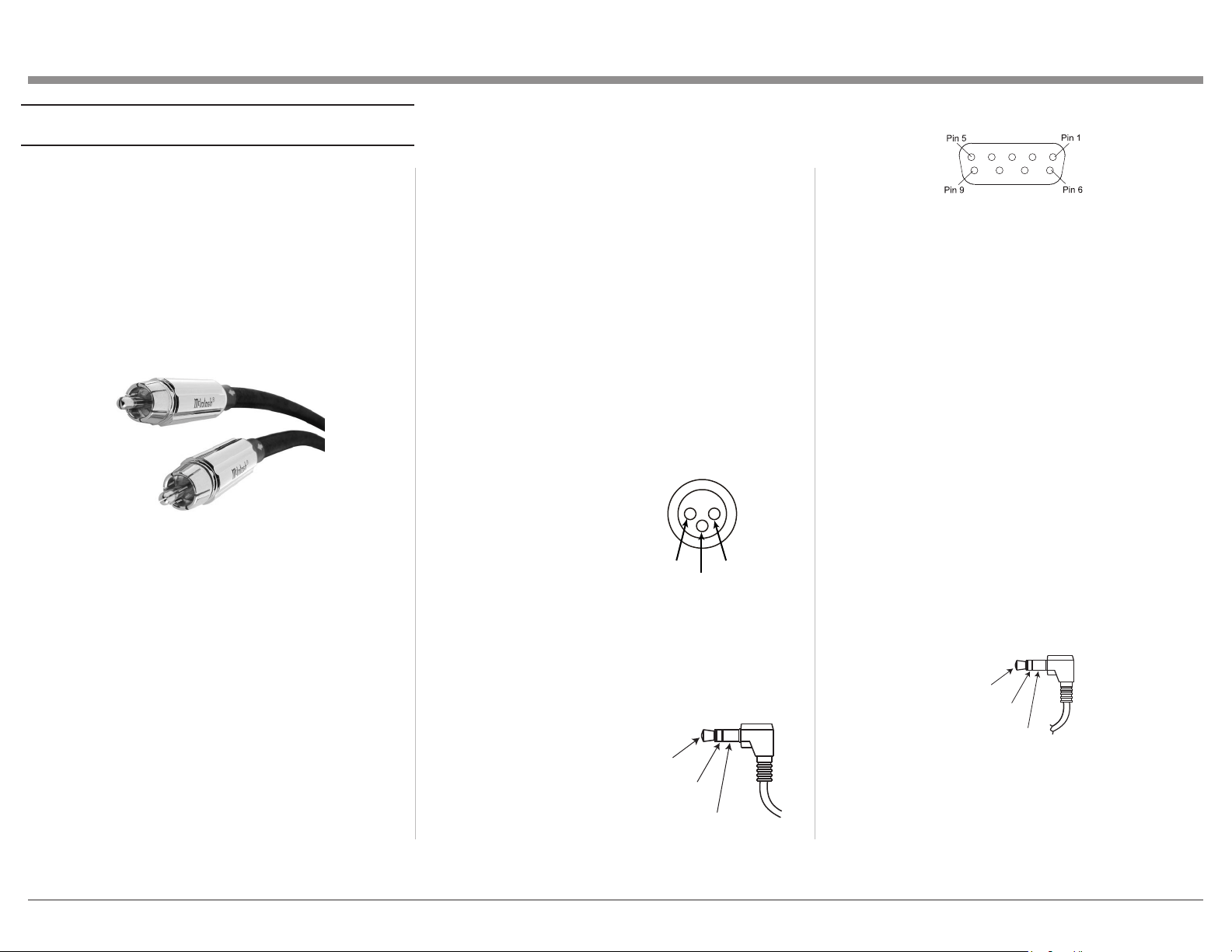
Unbalanced Inputs such as the two PHONO INPUTS
and UNBALANCED INPUTS 1 through 6 use
RCA/phono cables (see Figure 01) to connect the
MA12000 to other components. Traditionally, the
red connector is used to connect the right channel.
You are free to break tradition but keep the channels
straight or left and right might be reversed.
The MA12000 can accept the analog input from a
wide variety on components such as CD players,
tuners, and turntables. There are two sets of
unbalanced inputs dedicated for turntable
connections which allow customization of the input
level. See “Phono Adjustments” on page 28 . The
signal strength from phono cartridges vary and are
lower than the line level received from most other
components. The turntable will also have a ground
connection which should be secured to the
MA12000’s GND Binding Post to eliminate ground
hum. Turn the Binding Post counterclockwise to
loosen and attach the ground wire. Turn the Binding
Post clockwise to secure the ground connection.
The MC PHONO INPUT should be used for low
output Moving Coil Cartridges. The MM PHONO
INPUT should be used for Moving Magnet and high
output Moving Coil Cartridges.
Balanced/XLR Input and Output
The BALANCED INPUT allows a source to be
connected using XLR (balanced) cables if the source
has this option.
XLR cables can also be used to connect the
MA12000 to an external amplier. OUTPUT 2 has a
pair of XLR connectors labeled R for Right and L for
Left. To use the XLR output, connect the OUTPUT
2 R jack to the right input of your amplier and
OUTPUT 2 L jack to the amplier’s left input.
Below is the Pin conguration for the XLR Balanced
Input and Output Connectors on the MA12000.
Refer to the diagrams for connections:
PIN 1: Shield/Ground
PIN 2: + Signal
PIN 3: - Signal
RS232
The RS232 jack is used to connect the MA12000
to automation controller devices with RS232
connectors. To utilize this feature, you will need an
appropriate RS232
Data Cable. The
RS232 Data Cable
should be an 1/8
inch (3.5mm) stereo
mini phone plug to
a subminiature DB9
connector.
RS232 DB9 Connector Pin Layout
1. N/C (no connection) 6. N/C
2. Data In (RXD) 7. N/C
3. Data Out (TXD) 8. N/C
4. N/C 9. N/C
5. Gnd
Typical RS232 settings are:
• 8 data bits, no parity and one stop bit
• Baud rate xed at 115,200 bits per second
The baud rate can be changed in the Setup. See
“Comm Port Baud Rate” on page 24.
Wired IR Input
The IR Input allows an external IR receiver to be
attached to the MA12000. The Input is labeled IR
IN. By attaching an IR receiver using a 3.5mm cable
(Figure 09), the MA12000’s Remote Control can be
used in another location without a line-of-sight to the
MA12000’s front IR sensor.
IR Data
Control
Ground
N/C
If using an external IR receiver for the MAIN ZONE
in the same room as the MA12000, you may wish
to disable the front IR sensor. This will avoid
potential timing issues of receiving the Remote
Control’s commands from two different Inputs. The
Figure 01– RCA/Phono cables
PIN 1
PIN 2
PIN 3
Figure 02– XLR pin diagram
Figure 03– Mini plug for RS232
connection
Data In
(DB9-pin2)
Ground
(DB9-pin5)
Data Out
(DB9-pin3)
Figure 04– DB9 connector pin layout
Figure 05– IR 3.5mm connector
10
front IR can be turned on/off by doing the following:
• Press and Hold the Left Knob for two seconds
• Turn the Left Knob to the menu choice
“SETUP: Front IR”
• Turn the Right Knob clockwise for Enabled
(on) or counterclockwise (off)
• Press and release the Left Knob to exit the
Setup menu
AC Power
This connection is essential. Plug the female end of
the supplied AC Power Cord into the AC connector
(standard 15 ampere IEC) located in the rear right
corner of the MA12000. Plug the male end of the
AC Power Cord into a grounded and functioning AC
outlet.
Power Control (Trigger) Outputs
The MA12000 has three Power Control Outputs or
Triggers:
• MAIN
• TRIG 1
• TRIG 2
Power Control enables power on/off signals to go to
connected components so that other components can
automatically power on (or off) as called for by the
MA12000.
Connect components to the Triggers using a 3.5mm
stereo mini plug. See Figure 06. The Triggers work
by sending on/off signals in the form of +12 volt/0
volt to connected McIntosh components. See “Power
Control Triggers 1 and 2” on page 23.
Power
Control
Meter
Illumination
Control
Ground
Passthru
The MA12000’s PASSTHRU feature allows
your 2-channel system to be incorporated into a
multichannel system, typically as the left and right
front speakers. When the connected unit (Master)
powers on, it will take control of your MA12000.
The MA12000 will send the signal to your amplier
and speakers at a volume controlled by the Master.
The MA12000 preamplier is now a slave to
the source unit and you cannot control the sound
from this unit until the source unit is shutoff or
disconnected.
To use the PASSTHRU feature, connect the
controlling unit to the MA12000’s PASSTHRU
connector using the same type of cable as used for
Power Control (Trigger) Outputs. The MA12000
PASSTHRU jack should be connected to a Power
Control Trigger Output of the controlling unit.
To enable (or disable) PASSTHRU, enter Setup.
When enabled, an Input must be assigned to
PASSTHRU. When in PASSTHRU mode, the
MA12000 will send the signal from the assigned
Input to the MA12000’s Outputs. The volume will be
dictated by the controlling unit.
To turn off or assign an Input for PASSTHRU:
• Press and Hold the Left Knob for two seconds
• Turn the Left Knob to the menu choice
“SETUP: PASSTHRU”
• Turn the Right Knob to scroll through the
following options:
• Off
• Balanced
• Unbal 1
• Unbal 2
(Note: if you have changed an Input’s
name, the new name will appear.)
• Press and release the Left Knob to exit Setup.
Your choice will be saved
When in PASSTHRU mode, control of the
MA12000 is limited to the Trim functions: DISPLAY
BRIGHTNESS and AMP METER LIGHT. To
regain controls, the Controlling unit must be shut (or
Power Control cable removed from the PASSTHRU
connector.)
For an example Passthru diagram, see “Passthru
Example” on page 13.
Data Out
The MA12000 will convert IR Remote Control data
to share with McIntosh components connected to
the DATA PORTS. This will allow units that are
out of range of an IR signal to receive commands.
A McIntosh source can thereby be controlled by the
MA12000 Remote.
There are four DATA PORTS labeled 1 through 4.
To connect a McIntosh unit to a Data Port, use a
3.5mm stereo mini phone plug cable, see Figure 07.
Data
Signal
N/C
Data
Ground
Figure 06– Power control (trigger) mini plug
Figure 07– Data Port mini plug

11
Headphones
The MA12000 features High Drive Headphone
Amplication. The output of the High Drive
Headphone Amplication provides plenty of
power with the exibility to utilize a wide range
of headphones types including high impedance
headphones.
Connect your headphones using a stereo ¼ inch
plug to the HEADPHONES jack on the right of the
INPUT Knob. The initial volume of the headphones
will be the last volume used for headphones with a
startup limit of 70. When headphones are connected,
the other outputs will be muted unless this default
setting is changed in Setup.
The MA12000 Headphone Crossfeed Director
Circuitry (HXD
®
) improves the sound
localization for Headphone Listening. HXD
restores the directionality component of
the spatial sound stage normally heard with
Loudspeaker listening. HXD can be enabled or
disabled in Trim functions when headphones are
plugged in. The default is for the HXD circuit to
be on. To change the HXD setting:
• With headphones attached, press and
release the Left Knob (INPUT) to enter
Trim
• Turn Left Knob to the “HEADPHONE
HXD” screen
• Turn the Right Knob (VOLUME) to
choose On or Off
• Press and release the Left Knob to exit
(Trim screen will time-out and exit after
around 10 seconds of no input)
HDMI (ARC) and CEC
The MA12000 HDMI Input Connector has (ARC)
Audio Return Channel Circuitry, allowing the Audio
Selection and Control Command of HDMI TV/
Monitor Devices. To function properly, make sure
this feature is enabled in your TV’s setup menu.
To Activate or deactivate the Consumer Electronics
Control (CEC) functions of Volume or Power
control of the HDMI Devices connected to the
HDMI input, perform the following steps:
• Press and hold the Left Knob (INPUT) for two
seconds to enter Setup
• Rotate the Left Knob to the “SETUP: HDMI
CEC VOL” screen or the “SETUP: HDMI
CEC PWR” screen
• Turn the Right Knob (VOLUME) to
choose On or Off
• Press and release the Left Knob to exit
Lip Sync Mode (ARC)
The MA12000 HDMI Input Connector (ARC)
Audio Return Channel Circuitry, also has another
control function. When listening and viewing a TV/
Monitor HDMI Input Signal, the ARC circuitry
provides a synchronized Video and Audio TV/
Monitor Signal automatically.
To toggle the AUTO Synchronised Video and
AudioTV/Monitor Signal (or Lip Sync Mode) from
Auto to Manual, perform the following steps:
• Press and hold the Left Knob (INPUT) for two
seconds to enter Setup
• Rotate the Left Knob to the “SETUP: Lip
Sync Mode” screen
• Turn the Right Knob (VOLUME) to
choose Auto or Manual
• Press and release the Left Knob to exit
When Lip Sync Mode is set to Manual, an additional
Trim option will be available “HDMI LIP SYNC
DELAY” This allows an audio delay of between
0ms and 150ms to be manually set in 10ms
increments. To set delay:
• Press and release the Left Knob (INPUT)
to enter Trim
• Turn Left Knob to the “HDMI LIP SYNC
DELAY” screen
• Turn the Right Knob (VOLUME) adjust
the delay value from 0ms to 150ms
• Press and release the Left Knob to exit
(Trim screen will time-out and exit after
around 10 seconds of no input)
HDMI and Opcal Gain
Many video sources such as broadcast video to
television sets have sound levels that are lower than
typical music sources. Because of this, a volume
boost has been added to the HDMI input making
it louder. The ability to adjust the volume boost of
the Optical input has been added so that the Optical
input could be boosted as needed.
• Press and hold the Left Knob (INPUT) for two
seconds to enter Setup
• Rotate the Left Knob to the “SETUP: Digital
Gain” screen
• Press and hold the Left Knob for two seconds
• Turn the Left Knob to choose the Input
(HDMI, OPTI 1 or OPTI 2) to adjust
• Turn the Right Knob (VOLUME) to adjust the
Gain from 0dB to 15dB in 1dB increments
• Press and release the Left Knob to exit the
menu
12
USB
The USB input of the MA12000 provides the
capability to play music from a connected computer.
Software Requirements
Apple
®
Macintosh
®
computers require OS-10.6.8 or
later. Apple computers require no additional driver
install to communicate with the MA12000.
For Windows-based computers (PC), Windows 7
(SP1) or later is required. The correct McIntosh
USB Audio driver must be installed for the PC to
communicate with the MA12000.
To install the McIntosh USB Driver for Windows-
based computers:
Download the latest driver from the McIntosh
website: https://www.mcintoshlabs.com/products/
integrated-ampliers/MA12000
The driver can be found in the Downloads section
of the webpage under Software Updates. Choose the
DA2 Digital Audio Module: McIntosh USB Audio
Windows Driver
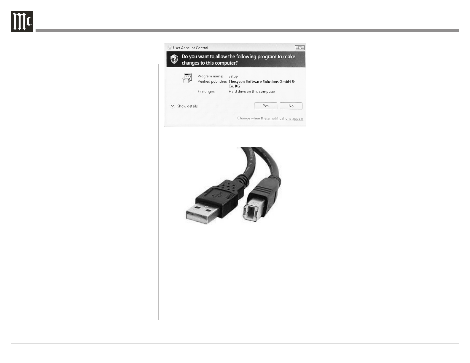
• Unzip the McIntosh_UsbAudio le
• Run the File
• Choose “Yes” to allow changes to your
computer (see Figure 08)
• Follow software prompts selecting “Next” or
“Install” as needed
• Click “Finish” when drvier is installed
Next, connect the Computer to the MA12000 using a
USB 2.0 Cable Type A to Type B (see Figure 09)
Windows should detect the new device (if you
installed the driver software as directed above) and
install the driver as indicated by a message in the
lower part of your monitor.
You can use the Windows Control Panel to select the
new audio device which will appear as “McIntosh
HD-HS2 USB Audio”. You may also select this
driver in many third-party applications such as
JRiver Media Center.
The MA12000’s display will show the sampling rate
or bit rate for the USB input.
Opcal
The two Optical Inputs allow digital sources to be
connected to the MA12000 using TOSLINK cables
also known as “optical audio cables.” The Optical
Inputs can handle high resolution digital audio up
to 192kHz/24-bit. The MA12000 DAC will process
standard format SPDIF PCM signals as well as
Dolby Digital and DTS encoded multi-channel bit
streams. Unsupported formats can result in strange
and/or unpleasant sounds.
Coax
The two Digital Coax (Coaxial) Inputs allow digital
sources to be connected to the MA12000 using
Digital Audio RCA Coaxial Cables. The Coax
Inputs can handle high resolution digital audio up
to 192kHz/24-bit. The MA12000 DAC will process
standard format SPDIF PCM signals as well as
Dolby Digital and DTS encoded multi-channel bit
streams. Remember, unsupported formats can result
in strange and/or unpleasant sounds.
MCT
The Digital MCT Input Circuitry of the MA12000
directly decodes SACD/CD signals (as well as PCM)
from an external Transport component. With MCT,
a secure digital connection is created, allowing for
the playback of the high denition audio found on
SACDs. Regular CDs can also be played over the
MCT connection. Use an MCT cable to connect the
MCT din jacks from the source to the MA12000. The
Digital MCT Cable is a McIntosh custom designed
cable and is included with McIntosh Transports.
The MCT cable is part number 171923 and can be
ordered from the McIntosh Parts Department.
Figure 08– Installing USB driver
software
Figure 09– USB Cable
13
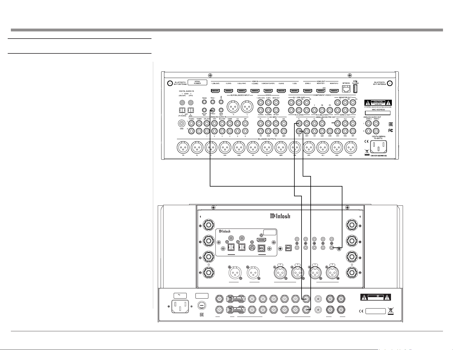
Passthru Example
The MA12000 can be part of a Multichannel Sound
System for BLU-RAY Audio, DVD Audio and Home
Theater Movies. The Right and Left Front Channels
from an Audio/Video Control Center can “Passthru”
the MA12000. In the following example the
UNBALANCED 6 Input will become the “Passthru”
input:
1. Connect Audio Cables from the A/V Processor
FL (Front Left) and FR (Front Right) Channel
Outputs to the MA12000 UNBALANCED
Number 6 INPUTS Left and Right Jacks.
2. Connect a Control Cable from the A/V Processor
TRIGger 2 Output to the MA12000 POWER
CONTROL PASSTHRU INPUT Jack.
See “Passthru” on page 10 for more information..
PU S H PU S H P US H
PU S H
FUSE
PUSH
MA12000 INTEGRATED AMPLIFIER
McINTOSH LABORATORY, INC., BINGHAMTON, NY
HANDCRAFTED IN USA WITH US AND IMPORTED PARTS
R OUTPUT
8Ω
4Ω
2Ω
CLASS 2 WIRING
R
L
OUTPUT 2
BALANCED INPUTS
2R 2L 1R
1L
L OUTPUT
8Ω
4Ω
2Ω
CLASS 2 WIRING
DATA PORTS
3
1
4
2
IR IN
RS232
EXT
CTRL
POWER CONTROL
OUTPUTS
MAIN
TRIG 1
PASSTHRU
INPUT
TRIG 2
SERVICE
PORT
120V 50/60Hz
6.6A
T 10AH 250V
FIXED 1 PWR AMP 1
2
OUTPUTS
UNBALANCED INPUTS
3 4 5 6
L
R
LR
GND
CAUTION
RISK OF ELECTRIC SHOCK
DO NOT OPEN
SERIAL
NUMBER
L
R
GND
MC
MM
PHONO
ATTENTION: RISQUE DE CHOC ELECTRIQUE-NE PAS OUVRIR
USB AUDIO
DA2 DIGITAL AUDIO MODULE
HDMI (ARC)
COAX 2
COAX 1
MCT
OPTICAL 2OPTICAL 1
DIGITAL AUDIO INPUTS
SERIAL
NUMBER
A/V Processor
14
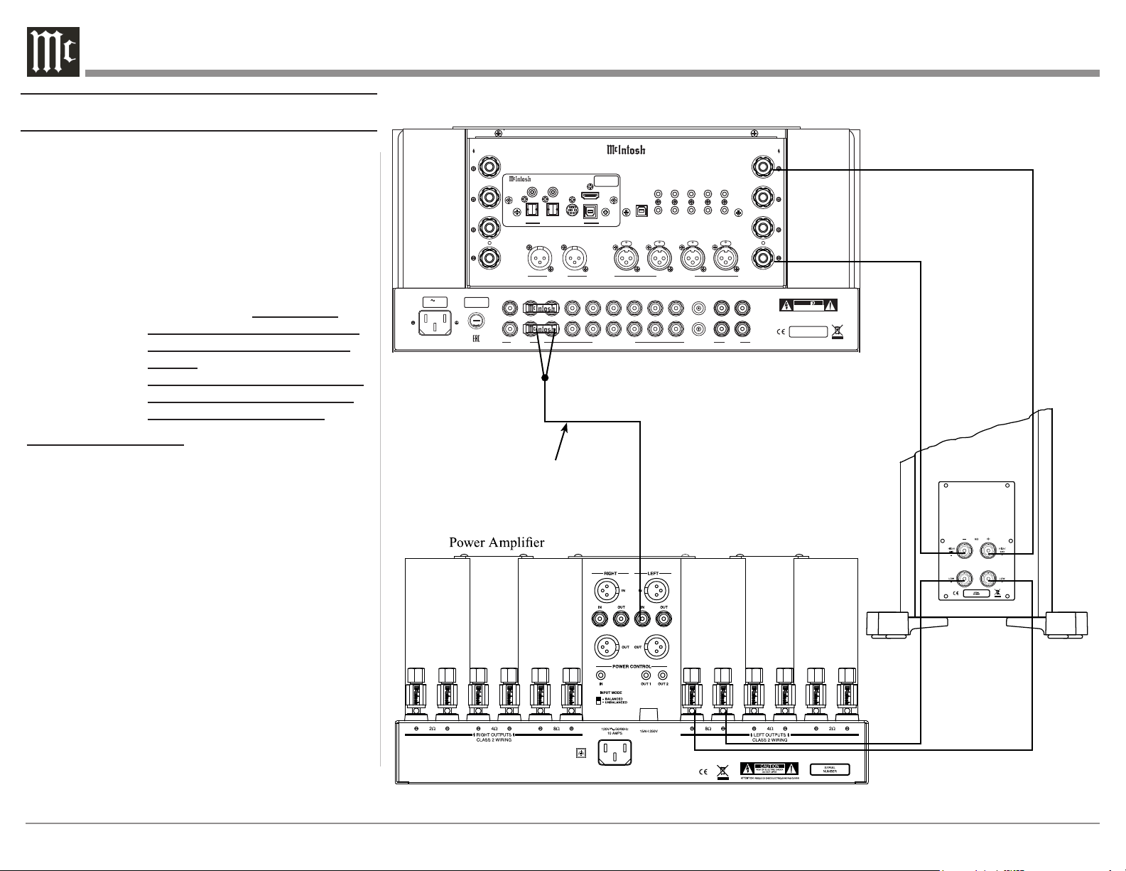
Connecng for Bi-Amplicaon
The MA12000 Power Amplifier Circuitry, together
with an additional separate Power Amplifier, may
be used to Bi-Amplify a Loudspeaker System. In
the illustration on this page, the Power Amplifier of
the MA12000 is connected to the Midrange/High
Frequency Section of the Loudspeaker. The additional
separate Power Amplifier is connected to the Low
Frequency Section of the Loudspeaker System.
Warning: The Loudspeaker System used for
Bi-Amplification must have the
jumpers removed from between the
MID/HIGH and LOW Frequency
Sections of the Loudspeaker System.
Failure to remove them could result
in damage to the MA12000 and/or
the separate Power Amplifier.
MA12000 Connections:
1. Remove the “McIntosh Jumpers” from between
the OUTPUT 1 Jacks and the PWR AMP In Jacks
located on the Rear Panel of the MA12000.
Note: Place the “McIntosh Jumper” in a safe place
for possible future use.
2. Using a pair of shielded RCA Type Audio “Y”
Adapters connect the OUTPUT 1 Jacks to the
PWR AMP In Jacks, for both Left and Right
Channels.
3. Connect the remaining unconnected part of the
“Y” Adapters to the separate Power Amplifier.
4. Referring to “How to Connect Loudspeakers”
on page 15, and the owner’s manuals for your
Power Amplifier and Loudspeaker, connect the
MA12000 Binding Post to the Loudspeaker MID/
HIGH Input Terminals.
Note: The Loudspeaker Connection illustrations
on this page are for the Left Channel.
Connect the Right Channel Loudspeaker in
the same manner.
PU S H PU S H P US H
PU S H
FUSE
PUSH
MA12000 INTEGRATED AMPLIFIER
McINTOSH LABORATORY, INC., BINGHAMTON, NY
HANDCRAFTED IN USA WITH US AND IMPORTED PARTS
R OUTPUT
8Ω
4Ω
2Ω
CLASS 2 WIRING
R
L
OUTPUT 2
BALANCED INPUTS
2R 2L 1R
1L
L OUTPUT
8Ω
4Ω
2Ω
CLASS 2 WIRING
DATA PORTS
3
1
4
2
IR IN
RS232
EXT
CTRL
POWER CONTROL
OUTPUTS
MAIN
TRIG 1
PASSTHRU
INPUT
TRIG 2
SERVICE
PORT
120V 50/60Hz
6.6A
T 10AH 250V
FIXED 1 PWR AMP 1
2
OUTPUTS
UNBALANCED INPUTS
3 4 5 6
L
R
LR
GND
CAUTION
RISK OF ELECTRIC SHOCK
DO NOT OPEN
SERIAL
NUMBER
L
R
GND
MC
MM
PHONO
ATTENTION: RISQUE DE CHOC ELECTRIQUE-NE PAS OUVRIR
USB AUDIO
DA2 DIGITAL AUDIO MODULE
HDMI (ARC)
COAX 2
COAX 1
MCT
OPTICAL 2OPTICAL 1
DIGITAL AUDIO INPUTS
SERIAL
NUMBER
+
-
Left Channel
Loudspeaker
“Y” adapter Cable
15
Caution: Do not connect the AC Power Cord to
the MA12000 Rear Panel until after the
Loudspeaker Connections are made. Failure to
observe this could result in Electric Shock.
The McIntosh MA12000 Power Amplifier Circuitry
is designed for Loudspeakers with an impedance
of 2 ohms, 4 ohms or 8 ohms. Connect a single
Loudspeaker only to the Right and Left Binding Post.
When connecting Loudspeakers to the MA12000
it is very important to use cables of adequate size,
to minimize power loss in the cables. The size is
specified in Gauge Numbers or AWG (American Wire
Gauge). The smaller the Gauge number, the larger the
wire size:
Loudspeaker Cable Distance vs Wire Gauge Guide
Loudspeaker
Impedance
25 feet
(7.62 meters)
or less
50 feet
(15.24 meters)
or less
100 feet
(30.48 meters)
or less
2 Ohms
12AWG 10AWG 8AWG
4 Ohms
14AWG 12AWG 10AWG
8 Ohms
16AWG 14AWG 12AWG
1. Prepare the Loudspeaker Hookup Cable for
attachment to the MA12000 Power Amplifier
Circuitry:
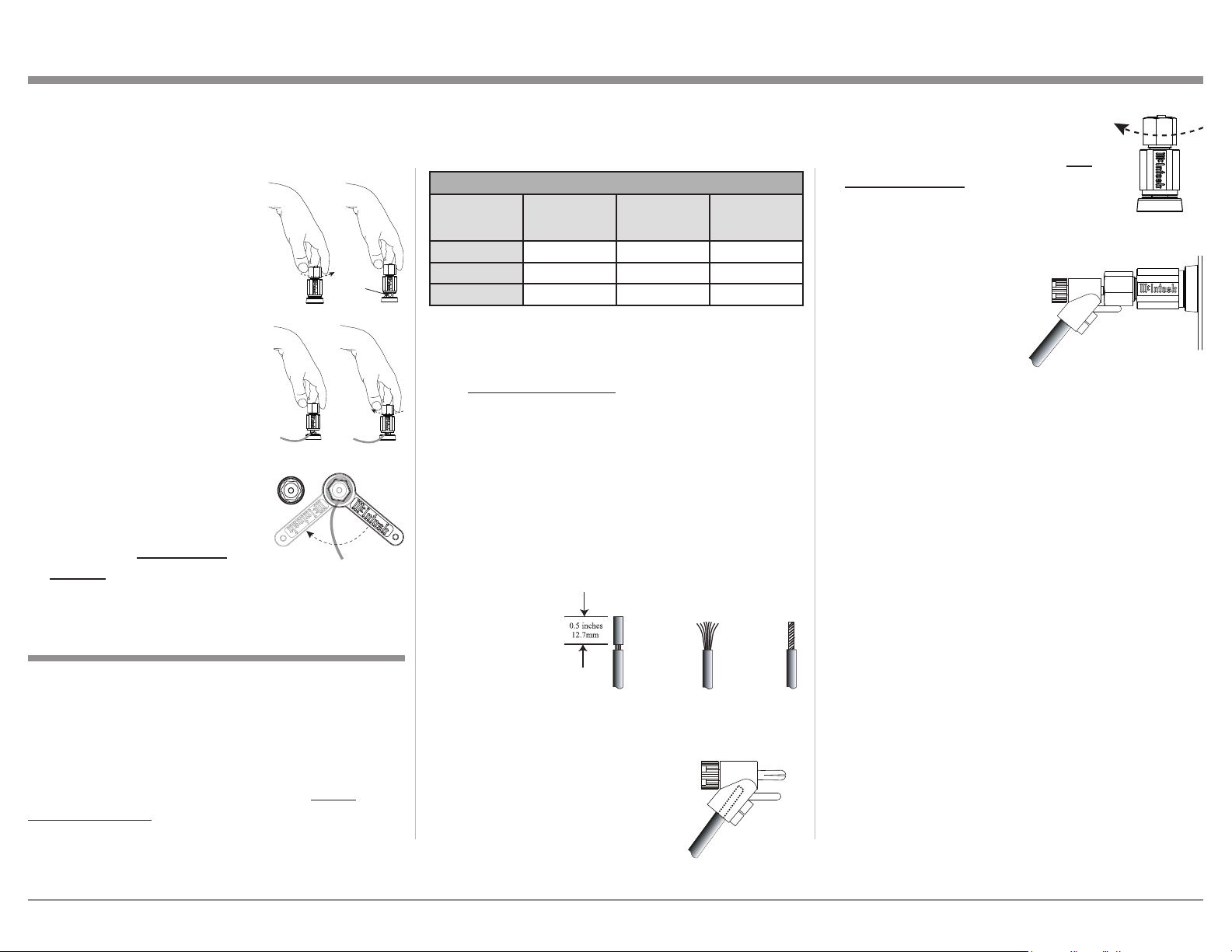
Bare wire cable ends:
Carefully remove sufficient insulation from the
cable ends, refer to figures F, G & H. If the cable
is stranded, carefully twist the strands together
as tightly as possible.
Notes: 1. If desired, the twisted ends can be tinned
with solder to keep the strands together.
2. The prepared bare wire cable ends may be
inserted into spade lug connectors.
3. Banana plugs are for use in the United
States and Canada only.
Banana Plugs are for use in the United States and
Canada only:
2. Attach the previously prepared
bare wire cable ends into the
banana plugs and secure the
connections. Refer to figure I.
3. Rotate the Binding Post clockwise
until it is nger tight. Refer to
gure J. Then using the McIntosh
Wrench, rotate the top of the Binding
Post one quarter of a turn (90°). Do
not over tighten. Refer to gure E.
4. Referring to figure K, connect the
Loudspeaker hookup cables with
banana plugs into the hole at the
top of the terminal
to the MA12000
Negative Binding Post
and Positive Binding
Post indentified as 2Ω
(ohms), 4Ω (ohms) or 8Ω
(ohms) connection to match the impedance of the
Loudspeaker, being careful to observe the correct
polarities.
If the Loudspeaker’s impedance is in-between
the available connections, use the nearest lower
impedance connection. Refer to “General
Information” Note 6 on page 4 for additional
information.
WARNING: Loudspeaker terminals are hazardous
live and present a risk of electric
shock. For additional instruction on
making Loudspeaker Connections
contact your McIntosh Dealer or
McIntosh Technical Support.
5. Connect the MA12000 power cord to an active AC
outlet.
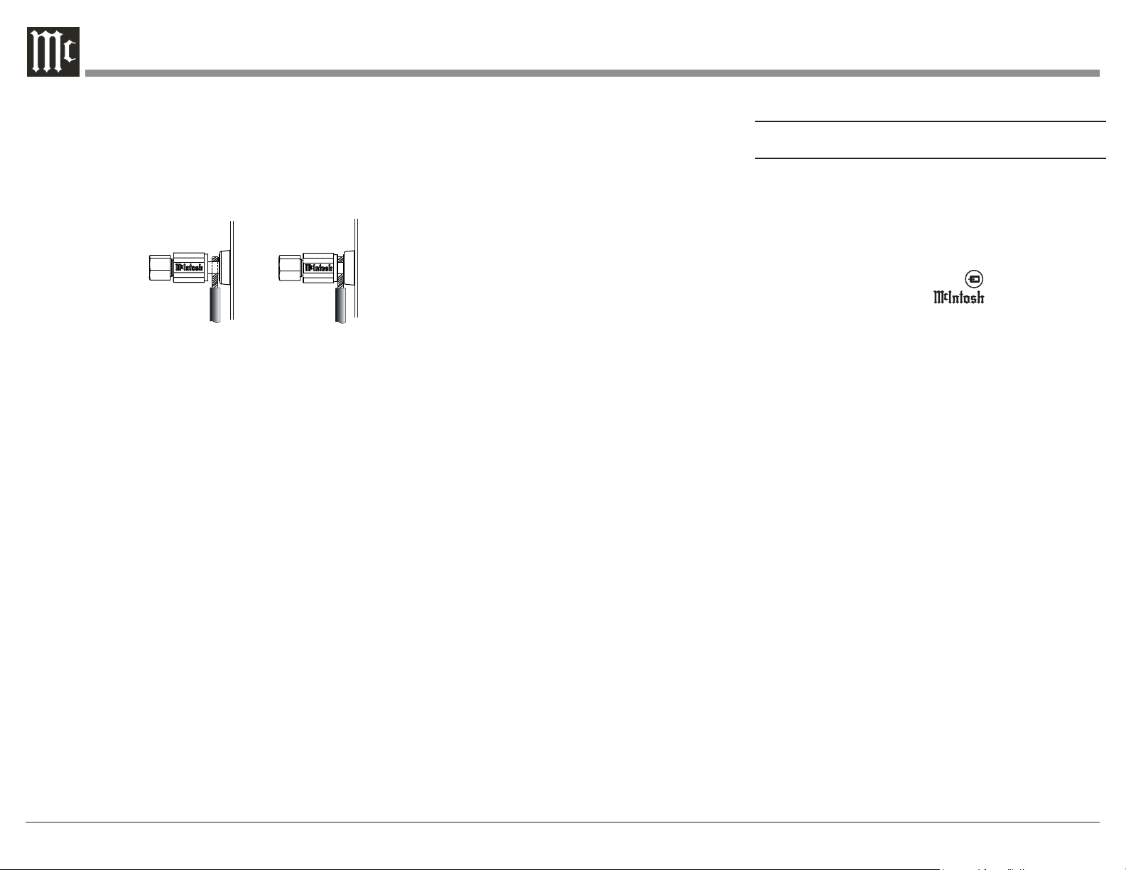
Spade Lug or Wire Connections:
6. Connect the Loudspeaker hookup cables to the
MA12000 Negative Binding and Positive Binding
indentified as 2Ω (ohms), 4Ω (ohms) or 8Ω
(ohms) connection to match the impedance of the
Loudspeaker, being careful to observe the correct
polarities. Insert the spade lug connector or
Solid Cinch™ Speaker Binding Posts
When connecting the Loudspeaker Hookup Cables to
the MA12000 Amplifier Binding Posts please follow
the steps below:
1. Rotate the top of the Binding
Post counterclockwise until
an opening appears. Refer to
gures A and B.
2. Insert the Loudspeaker
hookup cable into the Binding
Post opening or the cable
spade lug around the center
post. Refer to gure C.
3. Rotate the top of the Binding
Post clockwise until it is nger
tight. Refer to gure D.
4. Place the supplied McIntosh
Wrench over the top of the
Binding Post and rotate it
one quarter of a turn (90°) to
secure the Loudspeaker Cable
Connection. Do not over
tighten. Refer to gure E.
How to Connect Loudspeakers
Figure F
Figure G
Figure H
Figure I
Figure A
Opening
Figure B
Figure C Figure D
Figure E
Figure J
Figure I
Figure K
16
prepared section of the cable end into the terminal
side access hole, and tighten the terminal cap until
the cable is firmly clamped into the Binding Post
so the lugs or wire cannot slip out. Refer to figures
L and M.
If the Loudspeaker’s impedance is in-between
the available connections, use the nearest lower
impedance connection.
Note: The impedance of a Loudspeaker actually
varies as the Loudspeaker reproduces different
frequencies. As a result, the nominal impedance
rating of the Loudspeaker (usually measured at a
midrange frequency) might not always agree with the
impedance of the Loudspeaker at low frequencies
where the greatest amount of power is required.
Contact the Loudspeaker Manufacturer for additional
information about the actual impedance of the
Loudspeaker before connecting it to the McIntosh
MA12000.
WARNING: Loudspeaker terminals are hazardous live
and present a risk of electric shock. For additional
instruction on making Loudspeaker Connections
contact your McIntosh Dealer or McIntosh Technical
Support.
7. Connect the MA12000 power cord to an active AC
outlet.
Figure L
Figure M
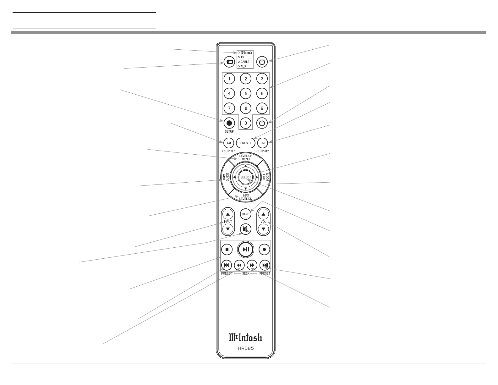
How to use the Remote Control
The supplied MA12000 Remote Control (HR085)
is capable of directly controlling the functions
of contemporary McIntosh Source Components
connected to the MA12000 via the Data Ports.
Notes: 1. If at any time the MA12000 seems
unresponsive to the HR085 Remote Control
Commands, press the DEVICE Push-
button to select first.
2. For additional information on using the
HR085 Remote Control with the McIntosh
Model, please refer to the “How to Operate”
starting on page 27.
3. For additional information on assigning the
Data Ports, refer to “Data Ports” on page
23.
Trim
Press the TRIM Push-button until the desired Trim
function (Balance, Trim Level, etc.) appears on the
MA12000 Front Panel Display, then press the LEVEL
Up or Down Push-button to adjust the Trim setting.
Note: Press the TRIM Push-button to recall the last
Trim function selected.
Output Selection
Press the BLUE (Setup) Push-button followed by
the AM (Output 1) or FM (Output 2) Push-button, to
control the Rear Panel Audio OUTPUTS 1, 2 (ON or
OFF) and Power Control TRIG 1 / TRIG 2.
Note: For additional information on assigning the
Outputs (1 and 2) and Power Control Triggers (1
and 2) refer to pages 22 and 23.
17
Note: Push-buttons whose function is not identified
above are for use with other McIntosh Products.
Press to Power the Integrated Amplifier ON
Use to select tuner presets, direct
access an AM/FM Station Frequency,
disc tracks or any numbered operation
Mutes the audio
Adjusts the VOLume level up or down
Selects FM Tuner Operating Functions, select Output 2
when used with the SETUP/shift Push-button and Track
Selection on certain McIntosh CD Players
LEDs illuminate when sending a remote command
and when programming the remote control
Press the Trim Push-button and then the
LEVEL UP Push-button to select and adjust
various functions. MENU is used with
McIntosh Models displaying choices on a
video screen
Press to Power the Integrated Amplifier OFF
Scrolls through the available INPUTs
Used to SELECT/Enter the indicated choice
Use p and q to tune Up or Down the AM/FM
Dial, use u and t for the next or previous HD
Radio Program (were applicable)
Activates the TRIM Mode. GUIDE is
used with McIntosh Models displaying
instructions on a video screen
Press to change Broadcast BANDs on a
connected Tuner. Select certain functions
on a variety of McIntosh Models
Select the DEVICE to select the target
for the remote control’s commands
Direct access to stored Tuner PRESETS when
used with the numeric Push-buttons (0 thru 9)
Press the Trim Push-button and then the
LEVEL DOWN Push-button to select and
adjust various functions. INFO is used with
McIntosh Models displaying information on
a video screen
Selects transport functions of STOP,
PLAY/PAUSE, RECORD, BACK
for the previous-selection, FAST-
REVERSE, FAST-FORWARD and
NEXT for the next selection
Selects Previous Tuner Station PRESET
Tuner scans Down the dial
to SEEK the next Station
Selects Next Tuner Station PRESET
Tuner scans Up the dial to
SEEK the next Station
SETUP Push-button is used as a
“Shift Key” to select a function
with blue color nomenclature
Selects AM Tuner Operating Functions, select Output 1
when used with the SETUP/shift Push-button and Track
Selection on certain McIntosh CD Players
EXIT the TRIM Menu and is used with McIntosh
Models displaying information or choices on a video
screen
Remote Control Diagram
18
Trim Funcons and Sengs
The Trim Functions allow you to make changes
quickly to many different settings. To access the Trim
Menus:
• Press and release the Left (INPUT) Knob
• Navigate by turning the Left Knob
• Change settings by turning the Right
(VOLUME) Knob
or use the Remote Control as described “How to use
the Remote Control” on page 16.
Trim Function Default Settings
BALANCE
Center
Transitions between full left and full right
INPUT TRIM
0dB
-12 dB to +12 dB in 1 dB increments,
EQUALIZER
Off
On or Off
MONO / STEREO
Stereo
Mono or Stereo
METER LIGHTS
On
On or Off
TUBE LIGHTS
On
On or Off
DISPLAY BRIGHTNESS
100%
Brightness adjustments: 25%, 50%, 75% or 100%
HDMI LIP SYNC DELAY
(This will only display
when the current INPUT is
HDMI and Lips Sync Mode
is set to Manual)
0 ms Between 0 ms and 150 ms in 10 ms increments
19
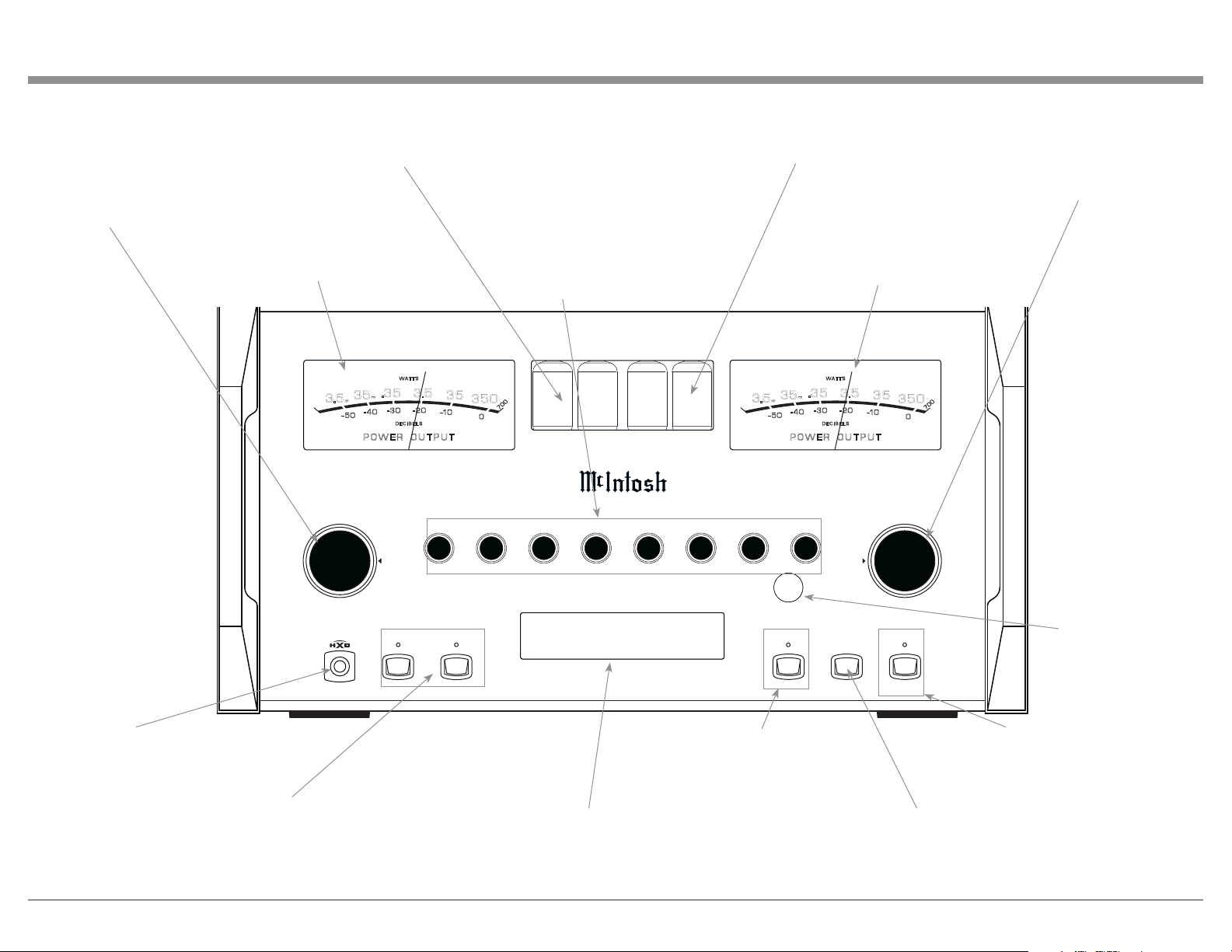
USB 35%
DSD256
HEADPHONE
1
2OUTPUTS EQUALIZER
MUTE
STANDBY/ON
RESET
PUSH - TRIM
HOLD - SETUP
TRIM / SETUP
ADJUST
25
VOLUME
I P T
50
100 200 400 1k 2.5k 10k
PUSH - TRIM
HOLD - SETUP
N U
M A 1 2 0 0 0
I N T E G R A T E D A M P L I F I E R
35
350
3.5
.35
P O W E R O U T P U T
- 50
- 30
D E C I B E L S
WA T T S
- 40
- 20
-10
0
3.5
m
35
m
7
0
0
35
350
3.5
.35
P O W E R O U T P U T
- 50
- 30
D E C I B E L S
WA T T S
- 40
- 20
-10
0
3.5
m
35
m
7
0
0
IR Sensor receives
commands from a
Remote Control
STANDBY/ON Push-button with
indicator switches the MA12000
ON or OFF (Standby) and resets the
microprocessors
MUTE Push-button mutes the
audio from the Loudspeakers
and Headphones
Right Channel
Amplifier Output
Meter
Two left Tubes will glow amber
when the Left Channel Amplifier
POWER GUARD circuit activates
and during Tube Warmup.
Left Channel
Amplifier Output
Meter
Two right Tubes will glow amber
when the Right Channel Amplifier
POWER GUARD circuit activates
and during Tube Warmup
OUTPUT 1 and 2 Push-buttons
with indicators, switch Preamplifier
Output (Loudspeakers) 1 and 2 On
or Off
INFORMATION DISPLAY indicates the
Sources, Volume, other Audio Settings,
Operational Functions and Setup Mode
Settings
EQUALIZER Push-button with
indicator, when deactivated
the audio signal bypasses the
Equalizer Controls
EQUALIZER Controls increase or decrease
the volume levels at the Center Frequencies
of 25Hz, 50Hz, 100Hz, 200Hz 400Hz,
1,000Hz, 2,500Hz and 10,000Hz
VOLUME Control allows
adjustment of the listening
level for both channels. Also
used to change the various
TRIM and SETUP Functions
Connection for low impedance
dynamic headphones, for private
listening
INPUT Control used to
select a source for listening
and recording. The control is
also used to enter the TRIM
or SETUP Modes and select
the various functions
20
How to Operate the Setup Mode
Your McIntosh MA12000 has been factory configured
to allow immediate enjoyment of superb audio without
the need for further adjustments. If you wish to make
changes to the factory default settings, a Setup Feature
is provided to customize the operating settings using
the Front Panel Information Display. Refer to the
MA12000 Front Panel Illustration on the previous
page while performing the following steps.
Note: If the MA12000 is currently On, proceed to
step 2.
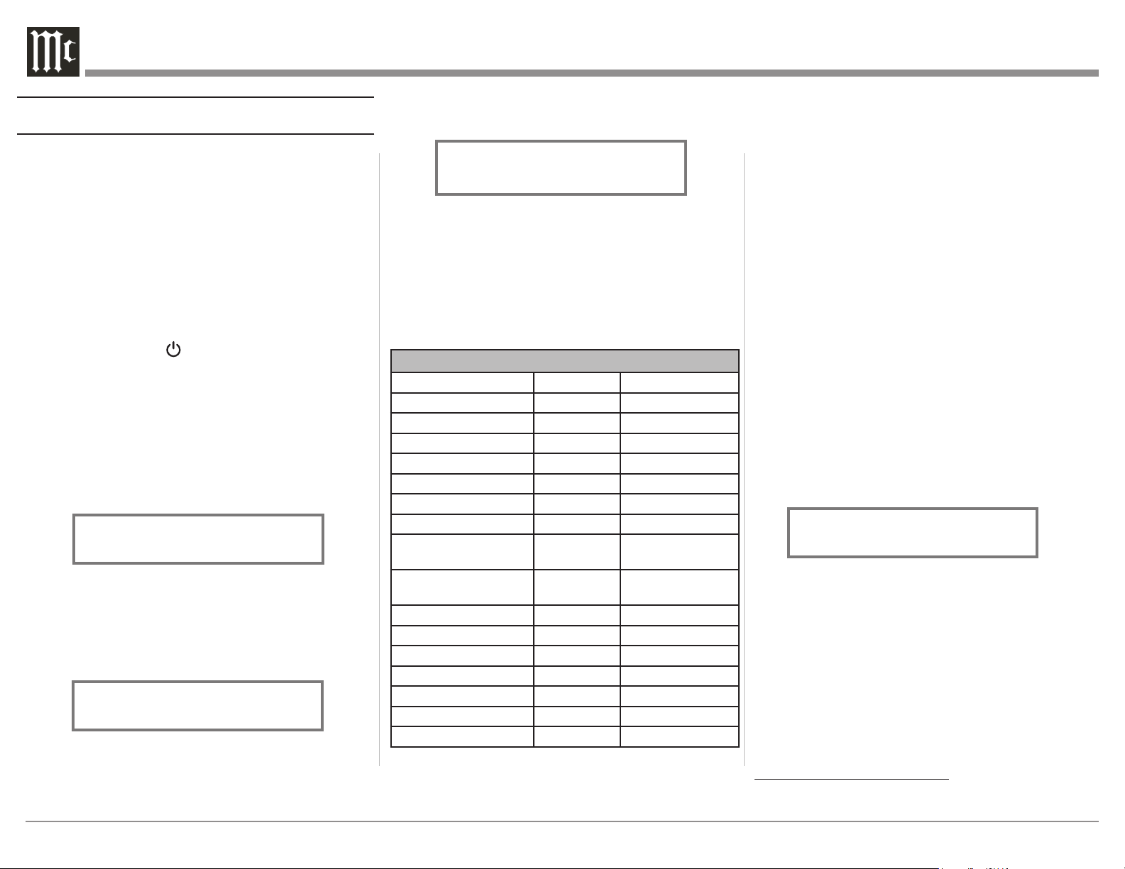
1. Press the STANDBY/ON Push-button on the Front
Panel or press the (Power ON) Push-button on
the Remote Control to switch On the MA12000.
The MA12000 will go through a brief startup
initialization with the Front Panel Information
Display first indicating “MA12000”, followed by
the last used source and volume setting. This is
followed by the volume setting indication starting
at zero and then increasing to the last used volume
setting. Refer to figure 1.
2. Press and hold in the INPUT Control until
the Front Panel Information Display indicates
“MA12000 V1.00, (or higher Main Firmware
version) - S/N: AFG____” (Serial Number).
Refer to figure 2.
3. Rotate the INPUT Control to select the Setup
Mode Menu item, “SETUP: Inputs, (Hold
INPUT)”. Continue to rotate the INPUT
CONTROL to view the other SETUP Mode
Options. Refer to figure 3.
4. To exit from the SETUP Mode, press and hold in
the INPUT Control and the Front Panel Display
will indicate its normal display. Refer to figure 1.
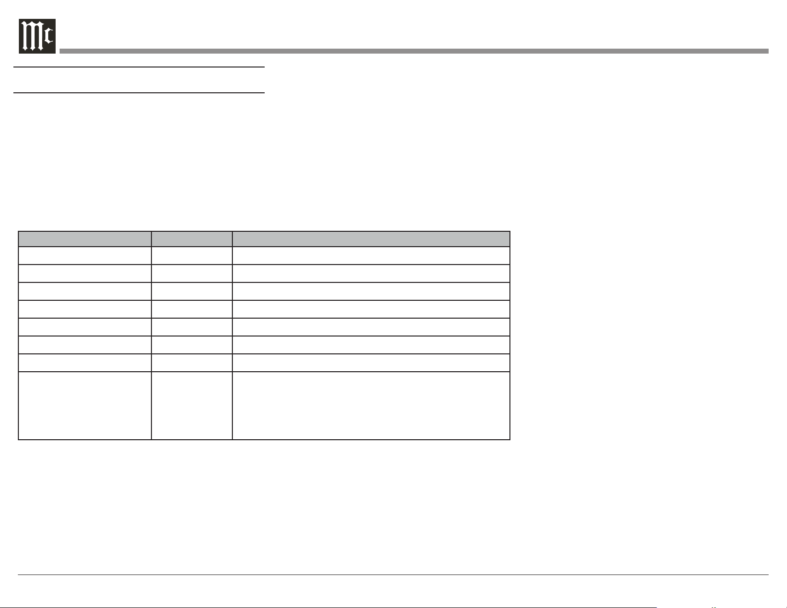
Default Sengs
The Default Settings Chart below indicates the
Function Name, Default Setting and options.
Default Settings
Function Name Default Options.
MA12000 V_._ _
DA2 V_._ _
INPUTS On / Rename Off
OUTPUTS (1 & 2) Switched Unswitched
Output (Headphones) Mute All Mute No Outputs
TRIGGER 1 Output 1 Main, Output 2
TRIGGER 2 Output 2 Main, Output 1
DATA PORTS
(1 thru 4)
All Data Specific Input
PASSTH RU
OFF
BAL or UNBAL
Inputs
HDMI CEC PWR/VOL ON Off
Lip Sync Mode Auto Manual
HDMI/OPTI 1 or 2 Gain 0dB 0db to 15dB
RS232 (Rate) 115200 Baud 9600 to 115200
Remote Control Codes Normal Alternate
Front IR Sensor Enabled Disabled
Auto-Off Enabled Disabled
Figure 2
MA12000 V1.00
S/N: AFG____
Figure 1
BAL 1 15%
Input Sengs
The MA12000 provides the ability to switch unused
INPUTS Off (or back On if they have been previously
switched Off). The default INPUT Names can
be changed to match the name of the component
connected to it or any other custom name desired
(within 10 Characters).
INPUT SWITCHED ON/OFF:
Firmware Version
The MA12000 functionality is controlled by internal
software that is know as Firmware. There are two
Firmware Identification Numbers for the MA12000.
The first Firmware Number is for the Main Circuitry
of the MA12000 and can be identified at any time by
utilizing the Setup Mode.
1. Press and hold in the INPUT Control to enter
Setup Mode.
2. Referring to the Front Panel Information
Displaythe number after the character “V” is the
Firmware number. Refer to figure 2.
To view the second Firmware Number, which is for
the Digital Audio Circuitry of the MA12000, perform
the following steps:
3. Press and hold in the INPUT Control to enter
Setup Mode.
4. Rotate the INPUT Control until the Front Panel
Information Display indicates “DA2 Firmware,
V1.00” (or higher Digital Audio Firmware
version). Refer to figure 4.
5. To exit the Setup Mode, press the INPUT Control.
Figure 3
SETUP: Inputs
(Hold INPUT)
Figure 4
DA2 FIRMWARE
V1.00
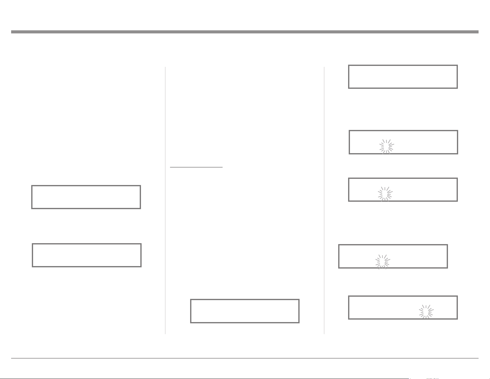
21
select the BAL Input. Refer to figure 8.
14. Press and hold in the INPUT Control until
“RENAME: BAL, >BAL < ” appears on the
Display. The character “B” is flashing to indicate
it is ready to be changed. Refer to figure 9.
15. Rotate the VOLUME (ADJUST) Control to change
the character “B” to “M”. Refer to figure 10.
16. Rotate the INPUT Control until the character “A”
is flashing, then rotate the VOLUME (ADJUST)
Control to change the character “A” to “E”. Refer
to figure 11.
Repeat this process until the desired word is spelled
(in this case “MEDIA SVR”). Refer to Figure 17.
18. To save the new name, press and hold in the
INPUT Control until “SETUP: MEDIA SVR ON
/ Rename” appears on the Front Panel Information
SETUP MODE.
7. Rotate the INPUT Control until “SETUP: Inputs,
(Hold INPUT)” appears on the Information
Display.
8. Press and hold in the INPUT Control until
“SETUP: UNBAL 4, Off” appears on the Display.
If necessary rotate the INPUT Control to select the
UNBAL 4 Input. Refer to figure 6.
9. To switch the UNBAL 4 Input On, rotate the
VOLUME Control until the display indicates
“SETUP: UNBAL 4, On / Name”.
10. Exit the SETUP Mode by several presses of the
INPUT Control.
RENAME INPUT:
In the following example, the BAL (BALANCED)
Input will be renamed to MEDIA SVR).
The MA12000 Default Input Names (UNBAL 1,
BAL, COAX 1, etc.) as indicated on the Front Panel
Display can be customized to a different name up to
ten characters long (TUNER, CD PLAYER, etc.). The
available characters for renaming the input include the
following: ! < > * , / - _ 0 1 2 3 4 5 6 7 8 9 A B C D E
F G H I J K L M N O P Q R S T U V W X Y Z .
In the following example, the BAL Input will be
renamed to “MEDIA SVR”.
11. Press and hold in the INPUT Control to enter the
SETUP MODE.
12. Rotate the INPUT Control until “SETUP: Inputs,
(Hold INPUT)” appears on the Information
Display. Refer to figure 7.
13. Press and hold in the INPUT Control until
“SETUP: BAL, On / Rename” appears on the
Display. If necessary rotate the INPUT Control to
In the following example, the UNBAL 4 Input will be
switched Off.
Note: When an INPUT is swiched Off, its name
will no longer appear on the Front Panel
Information Display when using the INPUT
Control (Front Panel or Remote Control).
1. Press and hold in the INPUT Control to enter the
SETUP MODE.
2. Rotate the INPUT Control until “SETUP: Inputs,
(Hold INPUT)” appears on the Information
Display.
3. Press and hold in the INPUT Control until
“SETUP: UNBAL 4, On / Name (Hold INPUT)”
appears on the Display. If necessary rotate the
INPUT Control to select the UNBAL 4 Input.
Refer to figure 5.
4. To switch the UNBAL 4 Input Off, rotate the
VOLUME Control until the display indicates
“SETUP: UNBAL 4, Off”. Refer to figure 6.
5. Exit the SETUP Mode by several presses of the
INPUT Control.
In the following example, the UNBAL 4 Input will be
switched On.
Notes: 1. When an INPUT is swiched ON, its name will
appear on the Front Panel Information Display
when using the INPUT Control (Front Panel or
Remote Control).
6. Press and hold in the INPUT Control to enter the
Figure 6
SETUP: UNBAL 4
Off
Figure 8
SETUP: BAL
On / Rename
Figure 10
RENAME: BAL
>MAL <
Figure 11
RENAME: OPTI
>MEL <
Figure 7
SETUP: Inputs
(Hold INPUT)
Figure 9
RENAME: BAL
>BAL <
Figure 5
SETUP: UNBAL 4
On/Name (Hold INPUT)
Figure 17
RENAME: BAL
>MEDIA SVR <
22
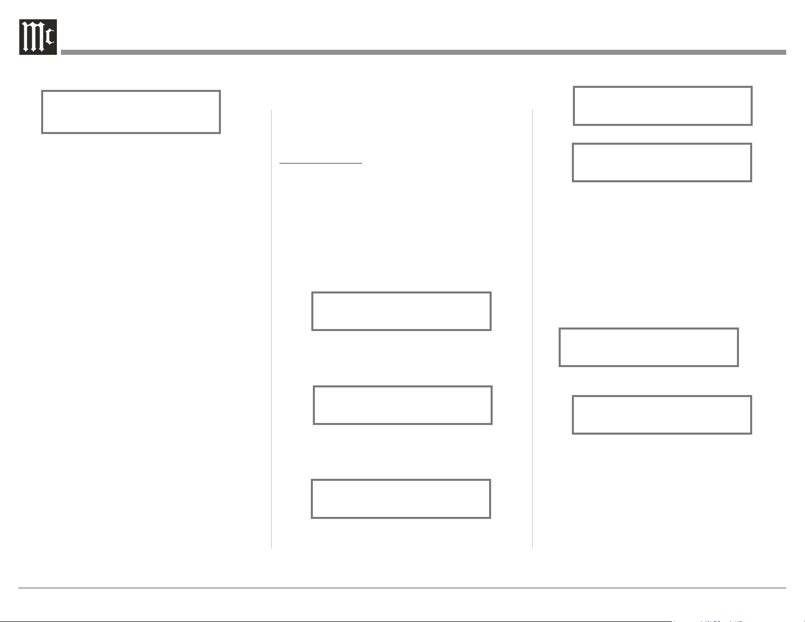
from the “Switched” setting to “Unswitched”.
Refer to figure 21.
5. In a similar manner, perform steps 3 and 4 to
change the OUTPUT 2 setting. Refer to figures 22
and 23.
The MA12000 Default Setting for using Headphones
is to automatically mute all the Output Connectors
when the Headphone Cable Plug is inserted into the
MA12000 Front Panel HEADPHONES Jack. There
are two available settings:
Mute All Outputs
Mute No Outputs
6. Rotate the INPUT Control until “SETUP:
HEADPHONES, Mute All Outputs ” appears on
the Information Display. Refer to figure 24.
7. Rotate the VOLUME (ADJUST) Control to change
the current HEADPHONES setting from “Mute
All Outputs” to “Mute No Outputs”. Refer to
figure 25.
8. Exit the SETUP Mode by several presses of the
INPUT Control.
Output Sengs
The Output Settings provide the ability to change how
the MA12000 Output 1, Output 2 and Headphones
function.
OUTPUT 1 and 2:
By default OUTPUT 1 and 2 are set to go On/Off by
using the Front Panel OUTPUT 1 and 2 Push-buttons
or by using the OUTPUT 1 and 2 Push-buttons on the
Remote Control. If it is desirable to have OUTPUT 1
and/or 2 always On regardless of the OUTPUT 1 and
2 Push-button settings, perform the following:
1. Press and hold in the INPUT Control to enter the
SETUP MODE.
2. Rotate the INPUT Control until “SETUP: Outputs,
(Hold INPUT)” appears on the Information
Display. Refer to figure 19.
3. Press and hold in the INPUT Control until
“SETUP: OUTPUT 1, Switched” appears on the
Display. Refer to figure 20.
4. Rotate the VOLUME (ADJUST) Control to change
Display. Refer to figure 18.
19. Exit the SETUP Mode by several presses of the
INPUT Control.
Figure 18
SETUP: MEDIA SVR
On / Rename
Figure 19
SETUP: Outputs
(Hold INPUT)
Figure 21
SETUP: OUTPUT 1
Unswitched
Figure 20
SETUP: OUTPUT 1
Switched
Figure 23
SETUP: OUTPUT 2
Unswitched
Figure 22
SETUP: OUTPUT 2
Switched
SETUP: HEADPHONES
Mute No Outputs
Figure 25
Figure 24
SETUP: HEADPHONES
Mute All Outputs
23
In the second example, Trigger 2 will activate when
the BAL Input is selected:
6. Rotate the INPUT Control to select “SETUP:
TRIGGER 2, Main” appears on the Display. Refer
to figure 30.
7. Rotate the VOLUME (ADJUST) Control until
“SETUP: TRIGGER 2, Input (Hold INPUT)”
appears on the Display. Refer to figure 31.
8. Press and hold in the INPUT Control until “SET-
UP: TRIGGER 2, Bal: OFF” appears on the
Display. Refer to figure 32.
9. Rotate the VOLUME (ADJUST) Control to select
“Bal : ON”. Refer to figure 33.
10. Exit the SETUP Mode by several presses of the
INPUT Control.
Power Control Triggers 1 and 2
By default the Power Control TRIGger 1 and TRIGger
2 are assigned to activate when Output 1 or Output
2 is selected. Triggers 1 and 2 can be reassigned to
function the same as the MAIN Power Control Jack or
be assigned to a given Input.
Note: The MAIN Power Control Jack is controlled by
the STANDBY/ON Front Panel Push-button and
the Remote Control Power Push-buttons.
In the first example, the Power Control Triggers 1
and 2 will be assigned to MAIN:
1. Press and hold in the INPUT Control to enter the
SETUP MODE.
2. Rotate the INPUT Control until “SETUP:
Triggers, (Hold INPUT)” appears on the
Information Display. Refer to figure 26.
3. Press and hold in the INPUT Control until
“SETUP: TRIGGER 1, Output 1” appears on the
Display. Refer to figure 27.
4. Rotate the VOLUME (ADJUST) Control to select
“MAIN” from the available additional selections
including Output 2 or Input. Refer to figure 28.
5. In a similar manner, perform steps 3 and 4 to
change the Trigger 2 setting from OUTPUT 2 to
Main. Refer to figures 29 and 30.
Figure 26
SETUP: Triggers
(Hold INPUT)
Figure 28
SETUP: TRIGGER 1
Main
Figure 27
SETUP: TRIGGER 1
Output 1
Figure 29
SETUP: TRIGGER 2
Output 2
Data Ports
Data Port Connections between the MA12000 and a
McIntosh Source Component allow for basic function
control of the source component using the MA12000
supplied HR085 Remote Control. By default, all of the
four Data Ports are set to send the same Data to the
selected source. To dedicate a given Data Port for only
one source component (example, source component
connected to the BAL Input will be assigned to Data
Port 1) perform the following Steps:
1. Press and hold in the INPUT Control to enter the
SETUP MODE.
2. Rotate the INPUT Control until “SETUP: Data
Ports, (Hold INPUT)” appears on the Information
Display. Refer to figure 34.
3. Press and hold in the INPUT Control until
“SETUP: DATA PORT 1, All Data” appears on
the Display. Refer to figure 35.
4. Rotate the VOLUME (ADJUST) Control to select
the “BAL” Input. Refer to figure 36.
5. In a similar manner, perform steps 3 and 4 to
assign any additional Data ports.
6. Exit the SETUP Mode by several presses of the
INPUT Control.
Figure 34
SETUP: Data Ports
(Hold INPUT)
Figure 35
SETUP: DATA PORT 1
All Data
Figure 36
SETUP: DATA PORT 1
BAL
Figure 30
SETUP: TRIGGER 2
Main
Figure 31
SETUP: TRIGGER 2
Input (Hold INPUT)
Figure 32
SETUP: TRIGGER 2
Bal : OFF
Figure 33
SETUP: TRIGGER 2
Bal : ON
24
Figure 18
Passthru
When the MA12000 is part of a Home Theater or
Multichannel Audio System the Right and Left Front
Channels from an Audio/Video Processor or Surround
Decoder can “Passthru” from the assigned MA12000
Input, into the MA12000 Power Amplifier Circurity.
The “Passthru” Audio Signal is also available for a
separate external Power Amplifier(s) via the number
1 Preamplifier Output Jacks. The Setup Mode allows
selection of the specified MA12000 Input to be used
for the Right and Left Front Channels. In the example
below, the Right and Left Front Channels from the
Audio/Video Processsor will be connected to the
UNBALANCED 6 INPUT Jacks on the MA12000.
Refer to page 9 for additional connection information.
Note: The Phono and Digital Inputs are not
assignable as a Passthru Input.
1. Press and hold in the INPUT Control to enter the
SETUP MODE.
2. Rotate the INPUT Control until “SETUP:
Passthru, Off” appears on the Information
Display. Refer to figure 37.
3. Rotate the VOLUME (ADJUST) Control to select
“SETUP: Passthru, UNBAL 6” Input. Refer to
figure 38.
4. Exit the SETUP Mode by several presses of the
INPUT Control.
SETUP: Passthru
UNBAL 6
Figure 38
SETUP: Passthru
Off
Figure 37
Comm Port Baud Rate
The MA12000 may be remotely controlled from other
equipment connected to the Rear Panel RS232 Jack.
The speed at which the MA12000 communicates (8
bit, no parity and 1 stop bit) with other equipment
is adjustable from 9,600 bits per second to 115,200
bits per second. To change from the default speed of
115,200 bits per second, perform the following steps:
1. Press and hold in the INPUT Control to enter the
SETUP MODE.
2. Rotate the INPUT Control until “SETUP:
RS232, 115200 Baud” appears on the Information
Display. Refer to figure 40.
3. Rotate the VOLUME (ADJUST) Control to select
the desired Baud Rate Speed.
4. Exit the SETUP Mode by several presses of the
INPUT Control.
Figure 40
SETUP: RS232
115200 Baud
25
Power Mode
The MA12000 incorporates an Auto Off Feature,
which automatically places the preamplifier into
the Power Saving Standby/Off Mode. This occurs
approximately 30 minutes after there has been an
absence of user activity (includes changes to any of
the Operation Functions such as source selection,
volume adjustment, etc.) or absence of an audio
signal. If it is desirable to disable the Auto Off Feature
perform the following steps:
1. Press and hold in the INPUT Control to enter the
SETUP MODE. 2. Rotate the INPUT Control
until “SETUP: Auto Off, Enabled” appears on the
Information Display. Refer to figure 45.
3. Rotate the VOLUME (ADJUST) Control to select
Disabled. Refer to figure 46.
4. Press the INPUT Control to exit the Setup Mode.
Figure 45
SETUP: Auto Off
Enabled
Figure 46
SETUP: Auto Off
Disabled
IR Sensor
The MA12000 Front Panel Sensor, which receives
the signals from the HR085 Remote Control, can be
switched off to prevent interference when an external
IR Sensor is connected. To de-activate the Front Panel
IR Sensor perform the following steps:
1. Press and hold in the INPUT Control to enter the
SETUP MODE. Refer to figure 2 on page 17.
2. Rotate the INPUT Control until “SETUP: Front
IR, Enabled” appears on the Information Display.
Refer to figure 43.
3. Rotate the VOLUME (ADJUST) Control to select
Disabled. Refer to figure 44.
5. Exit the SETUP Mode by several presses of the
INPUT Control.
Figure 43
SETUP: Front IR
Enabled
Figure 44
SETUP: Front IR
Disabled
Remote Control Codes
The HR085 Remote Control, included with the
MA12000, utilizes the NORMAL McIntosh Control
Codes. The second set of Control Codes the MA12000
will respond to is referred to as the ALTERNATE
Codes. The Alternate Codes are used when the
MA12000 is used in the same location as another
McIntosh Preamplifier and/or A/V Processor. This
will prevent the Remote Control from affecting the
operation of both units at the same time. To activate
the Remote Control ALTERNATE Codes perform the
following steps:
1. Press and hold in the INPUT Control to enter the
SETUP MODE. Refer to figure 2 on page 17.
2. Rotate the INPUT Control until “SETUP: IR
Codes, Normal” appears on the Information
Display. Refer to figure 41.
3. Rotate the VOLUME (ADJUST) Control to the
Alternate Codes. Refer to figure 42.
4. It is now necessary to change the HR085 Remote
Control over to the Alternate Codes. Information
on the HR085 Remote Control is available for
download from the McIntosh Web Site:
http://www.mcintoshlabs.com/us/Products/pages/
ProductDetails.aspx?CatId=preamplifiers&Produ
ctId=MA12000
5. Exit the SETUP Mode by several presses of the
INPUT Control.
Figure 41
SETUP: IR Codes
Normal
Figure 42
SETUP: IR Codes
Alternate
26
Factory Reset
If it becomes desirable to reset all the adjustable
settings (Setup and Trim Settings) to the factory
default values, perform the following steps:
1. Press and hold in the INPUT Control to enter the
SETUP MODE. Refer to figure 2 on page 17.
2. Rotate the INPUT Control until “FACTORY
RESET, (Hold INPUT)” appears on the
Information Display. Refer to figure 47.
3. Press and hold in the INPUT Control until
“FACTORY RESET, In Progress!” appears on
the Information Display, then release the INPUT
Control. Refer to figures 48 and 49.
4. Press the Front Panel STAND/BY Push-button to
switch On the MA12000.
Figure 49
FACTORY RESET
Completed!
Figure 47
FACTORY RESET
(Hold INPUT)
Figure 48
FACTORY RESET
In Progress!
Reset of Microprocessors
In the unlikely event the controls of the MA12000
stop functioning, the microprocessors can be reset by
performing the following:
1. Press the STANDBY/ON Push-button until the
STANDBY/ON LED Indicator switches Off in
approximately five seconds.
2. Then release the STANDBY/ON Push-button and
the MA12000 will switch Off.
3. When the STANDBY/ON LED is illuminated
press the STANDBY/ON Push-button, the
MA12000 will resume normal operation.
Note: This can be performed with the MA12000 On
or in the Standby Mode.
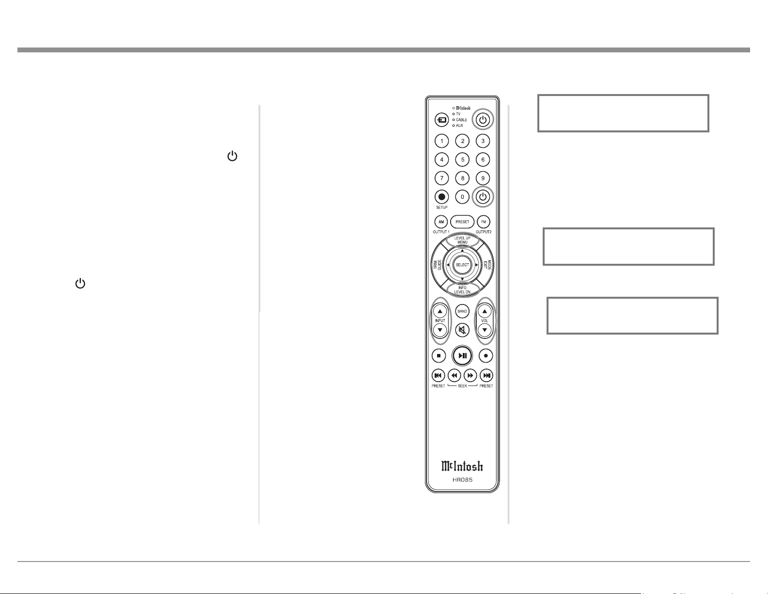
27
Meter Backlight, Display Brightness and HXD
Mode (when Headphones are connected). The Trim
Settings are stored in memory
independently for each Input
Source Selected, except the Meter
Illumination which is the same for
all inputs.
Note: Selection and Adjustment of
all Trim Functions may be
performed by pressing the
Front Panel INPUT Trim
Control and then rotating
it to select the desired Trim
Function. Then use the
VOLUME Adjust Control to
change the setting. Remote
Control TRIM Push-Button
together with the LEVEL UP/
Down Push-button may also
be used.
After approximately 5 seconds
the Display returns to indicate
the Source Selection and Volume
Level.
Balance
Listening balance varies with
different program sources, room
acoustics and listening positions
relative to the Loudspeakers. Use
the Balance (Trim Function) as
needed to achieve approximately
equal listening volume levels in
each Loudspeaker. To adjust the
Balance perform the following:
1. Press the TRIM Push-button
repeatedly on the Remote Control until “L
How to Operate the MA12000
Power On and Off
The Red LED above the STANDBY/ON Push-button
lights to indicate the MA12000 is in Standby mode.
To switch ON the MA12000, Press the STANDBY/
ON Push-button on the Front Panel or press the
(Power - Green) Push-button on the Remote Control.
The MA12000 will go through a brief startup
initialization with the Tubes glowing Amber. This
is followed by the volume setting indication starting
at zero and then increasing to the last used volume
setting. When Tube warmup is complete, the Tubes
will glow green (or off if TUBE LIGHTS Trim
setting is set to Off). To switch OFF the MA12000,
press the STANDBY/ON Push-button on the Front
Panel or the (Power - Red) Push-button on the
Remote Control.
Source Selection
Rotate the INPUT Control to select the desired
source or press the INPUT Upp or Downq Push-
button on the Remote Control. Refer to figure 53.
Volume Control
Rotate the Front Panel VOLUME Control or use
the VOLume Upp or Downq Push-buttons on the
Remote Control for the desired listening level. Refer
to figure 53.
Trim Functions
The MA12000 has various Trim Selections with
Adjustments. The Trim Functions include Balance,
Input Trim Level, Equalizer Mode, Phono Cartridge
Loading when a Phono Input is selected (Resistance
for MC and Capacitance for MM), Mono/Stereo,
BALANCE R, || ” appears on the Front Panel
Display. Refer to figure 54.
Note: The Front Panel INPUT/Trim Control may also
be used.
2. Rotate the VOLUME/Adjust Control or press the
LEVEL UP / DOWN Push-buttons on the Remote
Control to emphasize the Right Channel (refer to
figure 55) or the Left Channel (refer to figure 56).
The Front Panel Display indicates the relative Balance
changes. After approximately 5 seconds, the Display
returns to indicate the Source Selection and Volume
Level. To verify the Balance setting without changing
it, use the TRIM Push-button and select Balance.
Equalizer Mode
The built-in eight band Frequency Equalizer provides
more precise adjustment of sound than Bass and
Treble Controls. By default, the Equalizer is Off for all
Input Sources and the Equalizer Circuitry is bypassed.
Any Input Source may be assigned to have the
Equalizer On when selected. To activate the Equalizer
Figure 53
Figure 54
L BALANCE R
||
Figure 55
¦
¦
¦
¦
¦
¦
¦
¦
L BALANCE R
¦
Figure 56
¦
¦
¦
¦
¦
¦
¦
¦
¦
L BALANCE R
28
4. Temporarily exit TRIM Mode.
5. Select the MM Phono Input.
6. Select TRIM “PHONO CAPACITANCE, 50pF”
as indicated on the Front Panel Information
Display. Refer to figure 62B.
7. Rotate the VOLUME/Adjust Control or press
the LEVEL UP / DOWN Push-buttons on the
Remote Control to select the Capacitance Load
that comes closest to the Phono Cartridge Makers
recommended value.
After approximately 5 seconds the Alphanumeric
Display returns to indicate the Source Selection and
Volume Level.
Mono/Stereo Mode
By default the Stereo Mode is active for all Input
Sources however, any Input Source may be assigned
to Mono Mode. To change Stereo Mode to Mono for a
given Input Source, perform the following steps:
Note: The audio signal present at the FIXED OUT
Jacks is affected by the Stereo/Mono setting.
1. Select the desired Input Source.
2. Select “MONO / STEREO,
______
” as
indicated on the Front Panel Information Display.
Refer to figure 63.
3. To select MONO Mode adjust the TRIM LEVEL.
Refer to figure 64.
2. Adjust the Trim Level of each Input to match the
average volume level of the Input most frequently
listened to. The range of adjustment is ± 6.0dB in
half dB steps. Refer to figures 60 and 61.
After approximately 5 seconds the Information
Display returns to indicate the Source Selection and
Volume Level.
Phono Adjustments
When a Phono Input (MC or MM) is selected, an
additional TRIM SELECT FUNCTION becomes
available for adjustment. Perform the following steps
to make the Phono Trim Adjustment:
1. Select the MC Phono Source Input.
2. Select TRIM “PHONO RESISTANCE, 400Ω” as
indicated on the Front Panel Information Display.
Refer to figure 62A.
3. Rotate the VOLUME/Adjust Control or press
the LEVEL UP / DOWN Push-buttons on the
Remote Control to select the Resistance Load
that comes closest to the Phono Cartridge Makers
recommended value.
for a given Input Source, perform the following steps:
Note: The audio signal present at the FIXED OUT
Jacks is unaffected by the Equalizer settings.
1. Select the desired Input Source.
2. Select “EQUALIZER, Off” as indicated on
the Front Panel Information Display. Refer to
figure 57.
3. Set the EQUALIZER On for the desired Input
by using the Front Panel Volume Control or the
Remote Control Push-buttons may also be used to
switch the Equalizer On. Refer to figure 58.
After approximately 5 seconds the Information
Display returns to indicate the Source Selection and
Volume Level.
Trim Level
Source Components can have slightly different volume
levels resulting in the need to readjust the Volume
Control when switching between different sources.
The MA12000 allows the adjustment of levels for each
Source, ensuring the same relative volume. To adjust
the Trim Level for the currently selected Input Source
perform the following steps:
1. Select “INPUT TRIM” as indicated on the Front
Panel Information Display. refer to figure 59.
Figure 58
EQUALIZER
On
Figure 57
EQUALIZER
Off
Figure 59
INPUT TRIM
0.0 dB
Figure 61
INPUT TRIM
+4.0 dB
Figure 60
INPUT TRIM
-2.5 dB
Figure 62A
PHONO RESISTANCE
400
O
Figure 63
MONO / STEREO
______
Figure 62B
PHONO CAPACITANCE
50pF
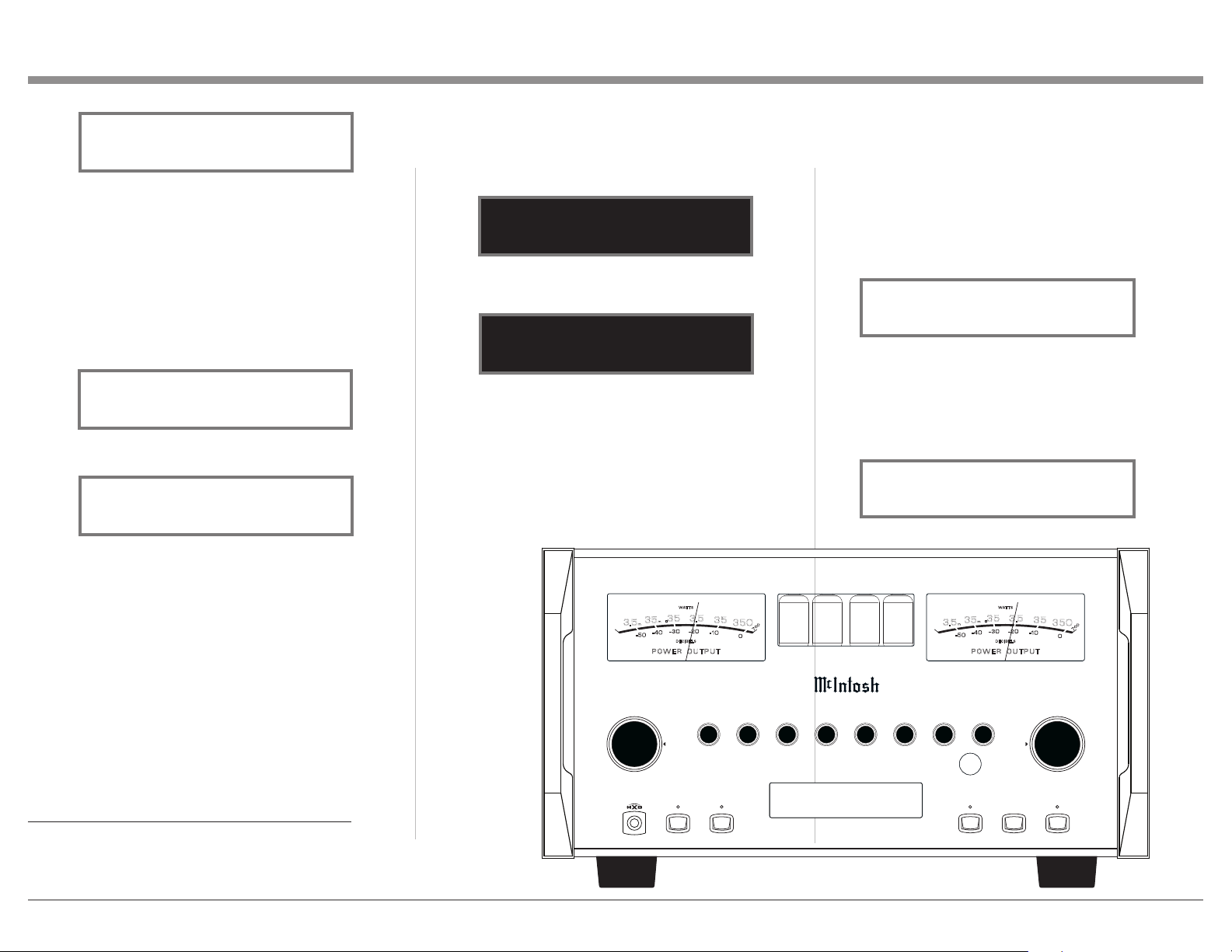
29
becomes available. McIntosh’s HXD brings the
acoustical depth and spatiality of music normally
heard with loudspeakers, to your headphones. The
default setting is HXD On. To switch HXD Off
perform the following:
1. Momentarily press the INPUT Control, then rotate
it to select “HEADPHONE HXD, On”. Refer to
figure 69.
2. To deactivate the HXD Mode rotate the VOLUME
Adjust Control until the Front Panel Display
indicates “HEADPHONE HXD, Off”. Refer to
figure 70.
performing the following:
1. Select “DISPLAY BRIGHTNESS” as indicated
on the Front Panel Information Display. Refer to
figure 67.
2. Reduce the Brightness level by adjusting the
TRIM LEVEL. Refer to figure 68.
After approximately 5 seconds the Information
Display returns to indicate the Source Selection and
Volume Level.
Headphone HXD
When headphones are connected to the MA12000
Front Panel Jack, an additional TRIM function
After approximately 5 seconds the Information
Display returns to indicate the Source Selection and
Volume Level.
Meter Backlight
The Front Panel Meter Illumination may be switched
On or Off by performing the following:
1. Select “METER LIGHTS, On” as indicated on the
Front Panel Information Display. See figure 65.
2. Switch Off the Meter Illumination. See figure 66.
After approximately 5 seconds the Information
Display returns to indicate the Source Selection and
Volume Level.
Notes: 1. Meter Illumination of recent McIntosh
Power Amplifiers will also switch On/Off
when connected to the MA12000 via a power
control cable.
2. Some A/V Processors will provide an On/Off
Control Signal when the MA12000 Passthru
Input Jack is connected to the A/V Processor
via the power control cable.
INFORMATION DISPLAY ILLUMINATION
The Brightness Level of the Front Panel Information
Display can be adjusted from bright to dim by
Figure 50
Figure 64
MONO / STEREO
____
Figure 65
METER LIGHTS
On
Figure 66
METER LIGHTS
Off
USB 35%
DSD256
HEA DPHONE
1
2OUT PUTS EQU ALIZER
MUT E
STAND BY/ ON
RES ET
PUS H - TRIM
HOL D - SETUP
TRI M / SETUP
ADJ UST
25
VOLUME
I P T
50
100 200 400 1k 2.5k 10k
PUS H - TRIM
HOL D - SETUP
N U
M A 1 2 0 0 0
I N T E G R A T E D A M P L I F I E R
35
350
3.5
.35
P O W E R O U T P U T
- 5 0
- 3 0
D EC IB E L S
WA T TS
- 4 0
- 20
-10
0
3.5
m
35
m
7
0
0
35
350
3.5
.35
P O W E R O U T P U T
- 5 0
- 3 0
D EC IB E L S
WA T TS
- 4 0
- 20
-10
0
3.5
m
35
m
7
0
0
Figure 67
DISPLAY
BRIGHTNESS
Figure 68
DISPLAY
BRIGHTNESS
Figure 69
HEADPHONES HXD
On
Figure 70
HEADPHONES HXD
Off
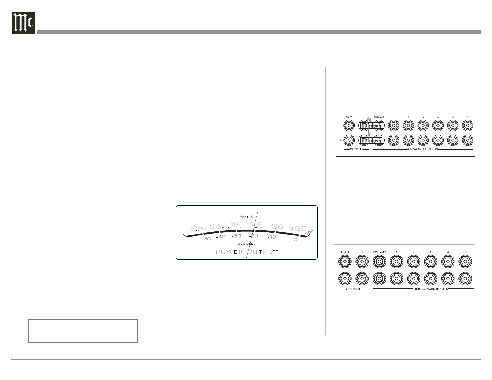
30
separate amplifier instead of the MA12000 built-in
Power Amplifier. Connect the Loudspeakers to the
separate Power Amplifier and remove the McIntosh
Jumpers that are located between the OUTPUTS 1
Jacks and the PWR AMP INPUT Jacks. Refer to
figure 73.
Note: The McIntosh Jumpers must be connected,
between the above mentioned jacks, when the
MA12000 Internal Power Amplifier is to be used.
The second way is to use both a separate Power
Amplifier and the MA12000 built-in Power Amplifier.
Connect one pair of Loudspeakers to the separate
Power Amplifier and the second pair to the MA12000.
Refer to the MA12000 Output Connection Diagrams
located on the separate folded sheet “Mc2B” and
figure 74.
Note: The MA12000 VOLUME Control will affect the sound
level of all the Loudspeakers.
Using Output 2
The MA12000 has provisions for connecting an
external Power Amplifier (to drive Loudspeakers
in another room) and an external sensor for remote
Pressing the Mute Push-button a second time or
adjusting the volume control will un-mute the
MA12000.
Headphones Jack
Connect a pair of dynamic headphones to the
Headphone Jack with a 1/4” (0.635cm) stereo phone
type plug for private listening. The default setting is
for Output Connections 1 and 2 to automatically mute.
For additional Information refer to “HEADPHONE
HXD” on this page.
Note: The Headphone Output is optimized for
impedances ranging from 100 to 600 ohms.
Power Output Meters
The MA12000 Power Output Meters indicate the
power delivered to the Loudspeakers. Refer to figure
72.
The meters respond to all the musical information
being produced by the Amplifier. They indicate to an
accuracy of at least 95% of the power output with only
a single cycle of a 2,000Hz tone burst.
Using a Separate Power Amplifier
There are two different ways to use a separate power
amplifier with a MA12000. The first way is to use the
Equalizer
Press the Front Panel EQUALIZER Push-button to
activate the MA12000 Equalizer Control Circuitry
for the currently selected Input Source. The LED
above the EQUALIZER Push-button will illuminate.
The MA12000 remembers for each selected Input
whether the Equalizer Control Circuitry is activated
or deactivated. To deactivate the Equalizer Control
Circuitry for the currently selected Input Source, press
the EQUALIZER Push-button and the LED above the
push-button will extinguish.
Note: 1. The audio signal present at the FIXED OUTPUT
Jacks is unaffected by the Equalizer Circuitry.
Trim
Press the Front Panel INPUT/TRIM Control to
activate the MA12000 Trim Functions. Rotate
the Front Panel INPUT/Trim Control to select the
desired Trim Function and then rotate the VOLUME/
Adjust Control to vary or make changes. Refer to
figure 50. The Remote Control TRIM and LEVEL
UP and LEVEL DOWN Push-buttons may also be
used. Approximately 5 seconds after Trim Function
Selection and/or adjustments have stopped, the the
Trim Mode switch off.
Mute
Press the MUTE Push-button to Mute the Audio in
Output 1 (Loudspeakers), Output 2 and Headphones.
The audio signals present at the FIXED OUTPUT
Jacks are not effected by activating the mute function.
The Front Panel Display will indicate the Source
Name and with the word MUTE in place of the actual
volume setting. Refer to figure 71.
Figure 71
COAX 1
MUTE
48kHz
Figure 72
35
350
3.5
.35
P O W E R O U T P U T
- 50
- 30
D E C I B E L S
WAT T S
- 40
- 20
-10
0
3.5
m
35
m
7
0
0
35
350
3.5
.
35
P O W E R O U T P U T
- 50
- 30
D E C I B E L S
WAT T S
- 40
- 20
-10
0
3.5
m
35
m
70
0
Figure 73
Jumpers
Figure 74
Jumpers Removed
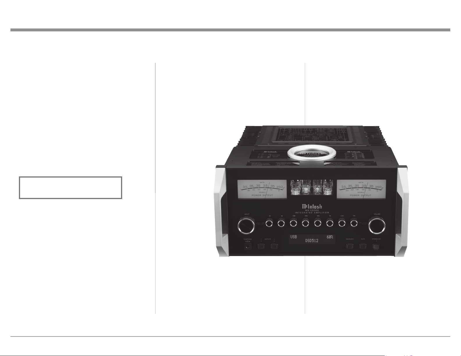
31
operation of the MA12000 from that room. With an
external Power Amplifier connected (as illustrated
on the McIntosh Connection Diagram separate
sheet “Mc2B”), press the Front Panel OUTPUT 2
Push-button or press on the Remote Control, the
BLUE (Setup) Push-button followed by pressing the
OUTPUT 2 Push-button to switch On or Off the
external Power Amplifier.
Passthru
When the MA12000 is connected together with
a McIntosh Multichannel A/V Control Center or
Surround Decoder and has the PASSTHRU Mode
activated, it will automatically turn-on when the A/V
Processor or Surround Decoder is turned On. It will
indicate on the Front Panel Display “PASSTHRU”.
Refer to figure 75.
The MA12000 OUTPUT 1 / OUTPUT 2 Front Panel
Push-buttons are active when in the Passthru Mode.
The other Front Panel Controls and Push-buttons are
deactivated as long as the Passthru Mode is active.
Optical and Coaxial Digital Inputs
When a Digital Input (Optical or Coaxial Connection)
on the MA12000 is selected, the Front Panel Display
will indicate the sample rate when a signal is present
such as “48kHz”.
During the time there is no Digital Signal present on
the selected input the display will indicate “______”.
Figure 75
PASSTHRU
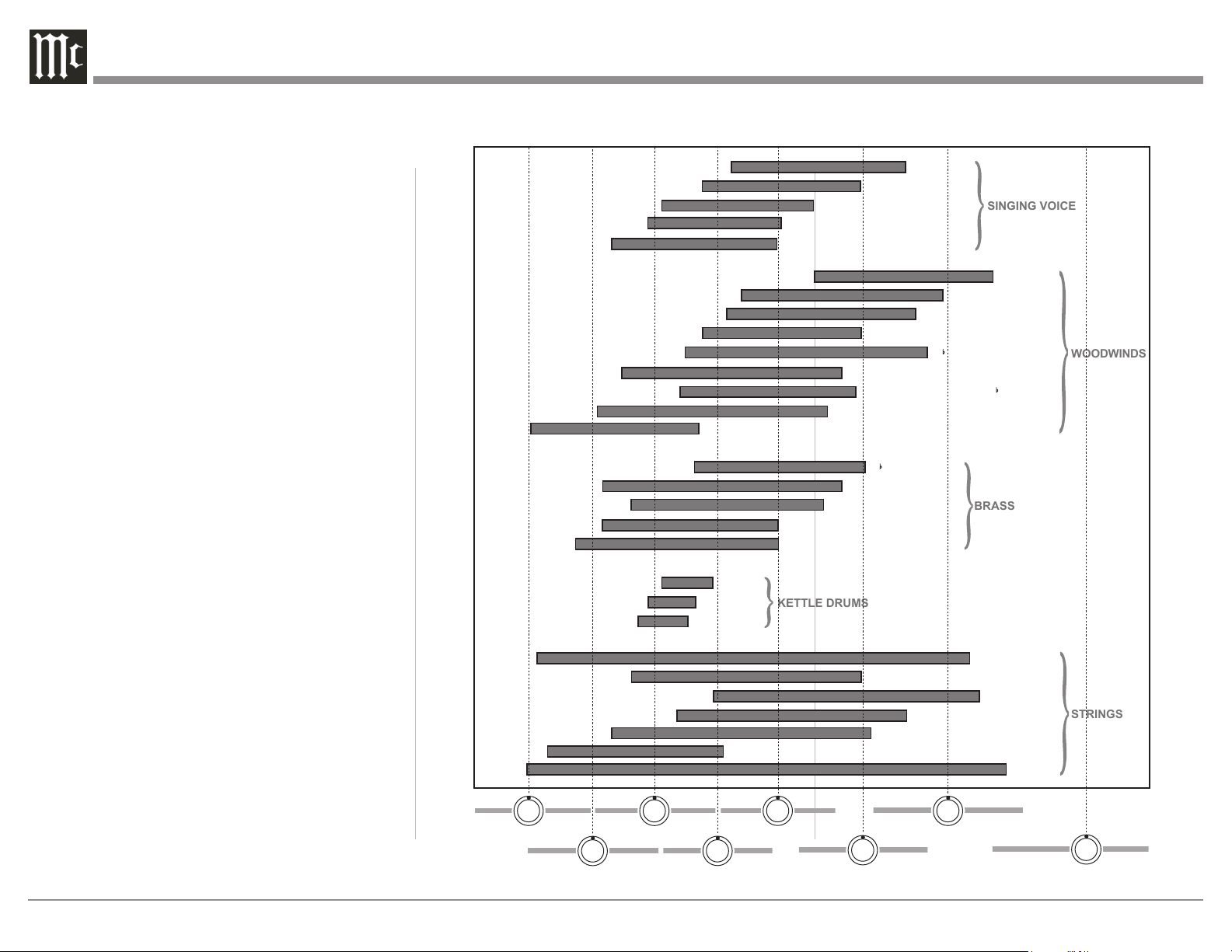
32
Fundamental Frequencies of Acoustical Musical Instruments and the Human Voice
SOPRANO
CONTRALTO
TENOR
BARITONE
BASS
PICCOLO
FLUTE
OBOE
ENGLISH HORN
B CLARINET
BASS CLARINET
ALTO SAXOPHONE IN B
BASSOON
CONTRABASSOON
B TRUMPET
FRENCH HORN IN F
TENOR TROMBONE
BASS TROMBONE IN F
TUBA
MEDIUM
SMALL
LARGE
HARP
GUITAR
VIOLIN
VIOLA
CELLO
BASS
PIANO
STRINGS
KETTLE DRUMS
BRASS
WOODWINDS
SINGING VOICE
50Hz
200Hz
1kHz
10kHz
25Hz
100Hz
400Hz
2.5kHz
Equalizer Controls
The MA12000 has eight signal strength controls that
can pass through, amplify or attenuate each, all or any
combination of the marked equalizer frequencies.
Equalization frequencies are set to 25Hz, 50Hz,
100Hz, 200Hz, 400Hz, 1,000Hz, 2,500Hz and
10,000Hz.
Frequency Controls are individually adjustable and
can provide up to +12dB maximum amplication and
-12dB attenuation.
Placing any Control Knob in the center detent position
removes the tone circuit components from the signal
path allowing the frequency of interest to pass through
unaltered.
The illustration to the right shows the fundamental
frequency range of acoustical musical instruments and
the human voice. It also shows the range of adjustment
of frequencies for each of the Equalizer Controls of
the MA12000 at the +6dB and -6dB points.
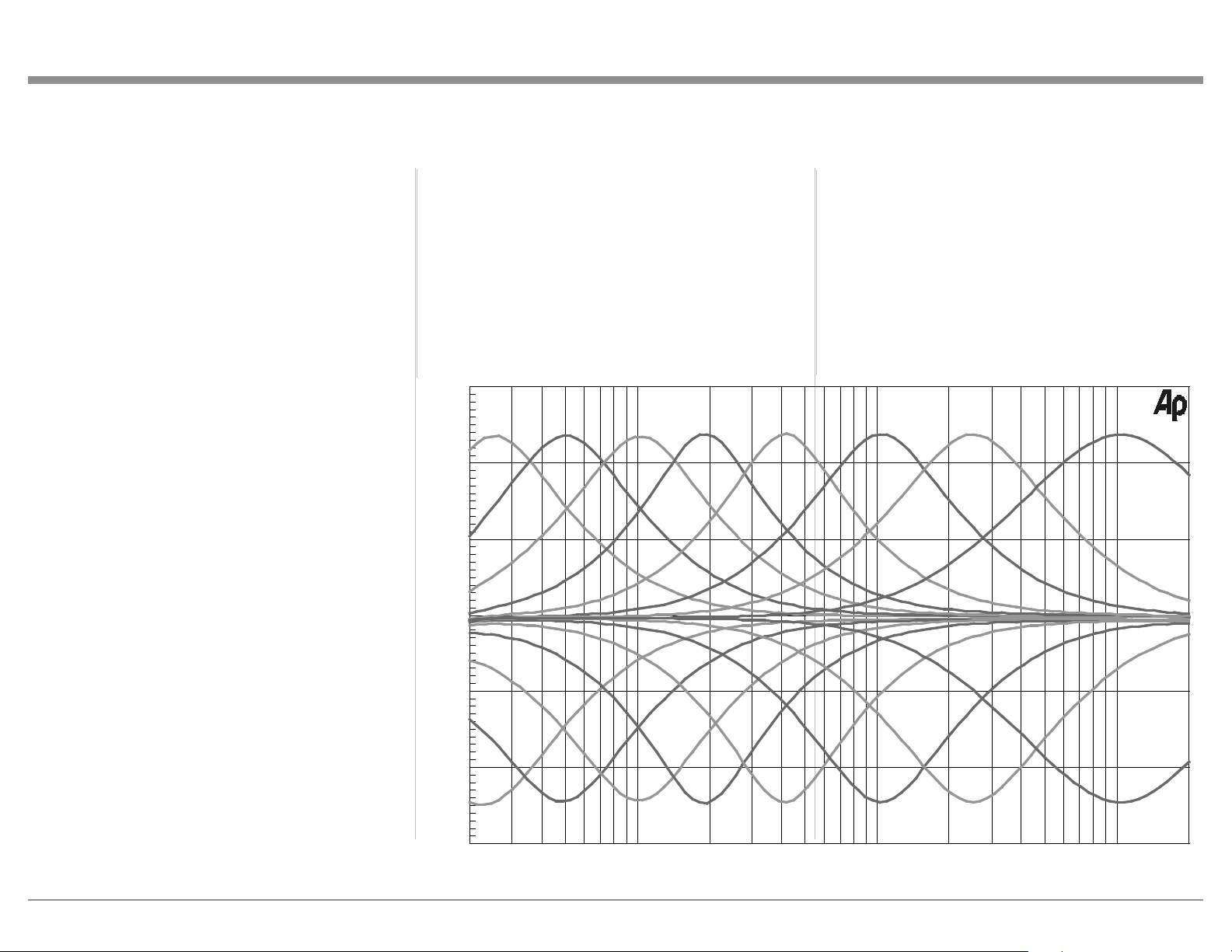
33
Preamplier Specicaons
Total Harmonic Distortion
0.03% maximum 20Hz to 20,000Hz
Intermodulation Distortion
0.03% maximum for any combination of frequencies
from 20Hz to 20,000Hz
Frequency Response
+0, -0.5dB from 20Hz to 20,000Hz
+0, -3dB from 10Hz to 100,000Hz
Preamplifier Output 1 and 2 (for rated input)
1.7V unbalanced (8V Maximum)
3.4V balanced (8V Maximum)
Preamplifier Output Impedance
220 ohms
Sensitivity (for rated output)
High Level - 300mV unbalanced
600mV balanced
Phono MM, 3.0mV
Phono MC, 0.3mV
Signal To Noise Ratio (A-Weighted)
High Level, 95dB below rated output
Phono MM, 77dB below 3mV input
Phono MC, 75dB below 0.3mV input
Input Impedance
High Level - 22K ohms Unbalanced
44k ohms Balanced
Phono MM - 50 to 400pF, in 50pF steps;
47K ohms
Phono MC - 50, 100, 200, 400 or 1,000 ohms;
100pF
Voltage Gain
High Level to Rec Output: 0dB
High Level to Output 1 and 2: 15dB
Phono MM to Rec Output: 40dB
Phono MC to Rec Output: 60dB
Phono MM to Output 1 and 2: 55dB
Phono MC to Output 1 and 2: 75dB
Maximum Input Signal
High Level, 8V unbalanced, 16V balanced
Phono MM, 80mV
Phono MC, 8mV
Headphone Impedance
100 to 600 ohms
Equalizer Controls
25Hz, 50Hz, 100Hz, 200Hz, 400Hz, 1,000Hz,
2,500Hz and 10,000Hz
20 50 100 200 500 1k 2k 5k 10k 20k
FREQUENCY IN HERTZ
0
- 5
A
M
P
L
I
T
U
D
E
I
N
D
E
C
I
B
E
L
S
-10
-15
+ 5
+10
+15

34
Power Amplifier Specifications
Power Output
Minimum sine wave continuous average power output
per channel, with both channels operating is:
350 watts into 2 ohm load
350 watts into 4 ohm load
350 watts into 8 ohm load
Output Load Impedance
2, 4 or 8 ohms
Rated Power Band
20Hz to 20,000Hz
26dB, 4 Ohms
23dB, 2 Ohms
Total Harmonic Distortion
0.005% maximum with both channels operating from
250 milliwatts to rated power, 20Hz to 20,000Hz
Intermodulation Distortion
0.005% maximum, if the instantaneous peak power
output does not exceed twice the rated power output
for any combination of frequencies from 20Hz to
20,000Hz.
Dynamic Headroom
1.5dB
Wide Band Damping Factor
Greater than 40
Power Guard
Less than 2% THD with up to 16dB overdrive at
1,000Hz
Frequency Response
+0, -0.25dB from 20Hz to 20,000Hz
+0, -3.0dB from 10Hz to 100,000Hz
Input Sensitivity (for rated output)
1.7 Volts
Signal To Noise Ratio (A-Weighted)
114dB below rated output)
Input Impedance
22,000 ohms
Maximum Input Signal
Power Amplifier In, 16V
Voltage Gain
29dB, 8 Ohms
Digital Audio Specicaons
Digital Input Signal Format
Coaxial and Optical Inputs - SPDIF (PCM)
MCT and USB Inputs - PCM, DSD
HDMI (ARC)- PCM, Dolby Digital, DTS
Digital Input Sample Rate
Optical: PCM - 16Bit, 24Bit - 44.1kHz to 192kHz
Coaxial: PCM -16Bit, 24Bit - 44.1kHz to 192kHz
MCT: PCM, SACD, -16Bit, 24Bit - 44.1kHz to 192kHz
USB: PCM - 16Bit, 24Bit, 32Bit - 44.1kHz to 384kHz
DXD - DXD352.8kHz, DXD384kHz
DSD - DSD64, DSD128, DSD256, DSD512
HDMI: PCM 24bit, 44.1kHz - 192kHz
DTS
Dolby Digital
Digital Inputs
Coaxial: 0.5V p-p/75 ohms
Optical: -15dbm to -21dbm (TOS Link)
MCT: 0.5V p-p/75 ohms
USB: USB Type B Connector
General Specicaons
Power Control and Trigger Output
12VDC, 25mA
Power Requirements
Field AC Voltage conversion of the MA12000 is not
possible. The MA12000 is factory configured for one
of the following AC Voltages:
100 Volts, 50/60Hz at 8.0 amps
110 Volts, 50/60Hz at 6.6 amps
120 Volts, 50/60Hz at 6.6 amps
127 Volts, 50/60Hz at 6.6 Amps
220 Volts, 50/60Hz at 3.6 amps
230 Volts, 50/60Hz at 3.3 amps
240 Volts, 50/60Hz at 3.3 amps
Standby: Less than 0.25 watt
Note: Refer to the rear panel of the MA12000 for the
correct voltage.
Overall Dimensions
Width is 17-1/2 inches (44.45cm)
Height is 9-7/16 inches (24.0cm) including feet
Depth is 22 inches (55.88cm) including the Front
Panel, Knobs and Cables
Weight
108 pounds (48.9 kg) net, 141 pounds (63.9 kg) in
shipping carton
Shipping Carton Dimensions
Width is 29-1/2 inches (74.93cm)
Height is 17 inches (43.18cm)
Depth is 29 inches (73.66cm)
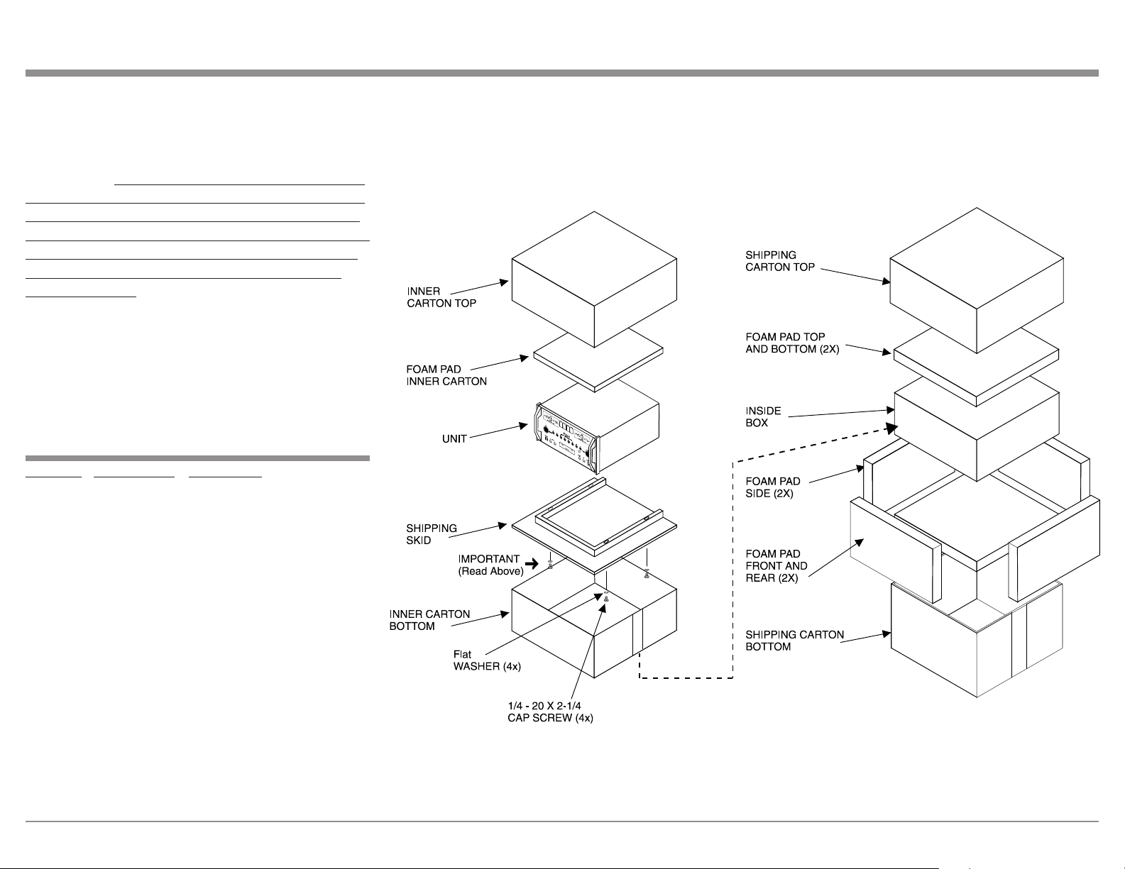
35
MA12000 Packing Material List
Packing Instrucons
In the event it is necessary to repack the equipment for
shipment, the equipment must be packed exactly as
shown below. It is very important that the four plastic
feet are attached to the bottom of the equipment. Two
1/4-20 x 2-1/4 inch screws and washers must be used
to fasten the unit securely to the bottom pad and wood
skid. This will ensure the proper equipment location
on the bottom pad. Failure to do this will result in
shipping damage.
Use the original shipping carton and interior parts
only if they are all in good serviceable condition.
If a shipping carton or any of the interior part(s)
are needed, please call or write Customer Service
Department of McIntosh Laboratory. Refer to page 2.
Quantity Part Number Description
1 034052 Shipping carton top
1 034051 Shipping carton bottom
2 034186 Front and rear foam pad
2 034187 Side foam pad
2 034054 Top and bottom foam pad
1 034136 Inner carton top
1 034137 Inner carton bottom
1 034188 Inner foam pad
1 034479 Shipping skid
4 401212 1/4-20 hex cap x 2-1/4 inch screw
2 104058 1/4 inch flat washer 1-1/2 inch
4 017937 Plastic foot
4 404080 #10 flat washer

The continuous improvement of its products is the
policy of McIntosh Laboratory Incorporated who
reserve the right to improve design without notice.
Printed in the U.S.A.
McIntosh Laboratory, Inc.
2 Chambers Street
Binghamton, NY 13903
www.mcintoshlabs.com
McIntosh Part No. 24110100