The water heater should not be located in an area where leakage from the tank or connections will result in damage to the area adjacent to the heater or to lower floors of the structure.
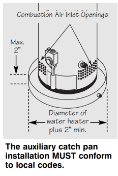
When such areas cannot be avoided it is recommended that a suitable catch pan, adequately drained, must be installed under the water heater.
The pan must not restrict air flow to the combustion air inlet openings (perforation openings) located around the lower perimeter of the water heater.
Catch pan kits are available from the store where the water heater was purchased, or any water heater distributor.
Make certain the floor underneath the water heater is strong enough to sufficiently support the weight of the water heater once it is filled with water
A gas fired water heater or any other appliance should not be installed in a space where liquids which give off flammable vapors are to be used or stored. Such liquids include gasoline, LP gas (butane or propane), paint or adhesives and their thinners, solvents or removers.
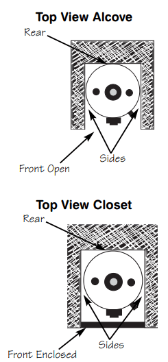
When installed in a closet, DO NOT block or obstruct any of the combustion air inlet openings located around the perimeter of the water heater. A minimum of 1” is required between these combustion air inlet openings and any obstruction.
Because of natural air movement in a room or other enclosed space, flammable vapors can be carried some distance from where liquids which give off flammable vapors are to be used or stored. The open flame of the water heater’s pilot or main burner can ignite these vapors and create a shut down condition of the water heater which will not allow the water heater to ignite until examined by a Qualified Service Technician.
The water heater must be located so it is not subject to physical damage, for example, by moving vehicles, area flooding, etc.
If local codes require the use of a stand kit to raise the water heater 18” above the floor, please contact the store where the water heater was purchased, or any water heater distributor. These kits must comply with local codes.
● The water heater should be installed as close as practical to the gas vent or chimney.
● Long hot water lines should be insulated to conserve water and energy.
● The water heater and water lines should be protected from exposure to freezing temperatures.
● Do not install the water heater in bathrooms, bedrooms, any occupied rooms normally kept closed, or in unprotected outdoor areas.
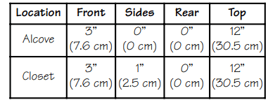
● Minimum clearance from combustible construction:
If the clearances stated on the Instruction/Warning Label, located on the front of the heater differ, install the water heater according to the clearances stated on the label.
● If the water heater is installed in an alcove or closet, the entire floor must be covered by a wood or metal panel. A minimum of 24” clearance from the front and top should be available for adequate inspection and servicing.
● The water heater may be installed on combustible floors, but not directly on carpeting. If the water heater must be installed on carpeting, place a metal or wood panel beneath the water heater, extending beyond its full width and depth at least 3” in all directions.
Inspect Shipment
Inspect the water heater for possible damage. Check the markings on the rating plate of the water heater to be certain the type of gas supplied corresponds to the water heater requirements.
Water Supply Connections
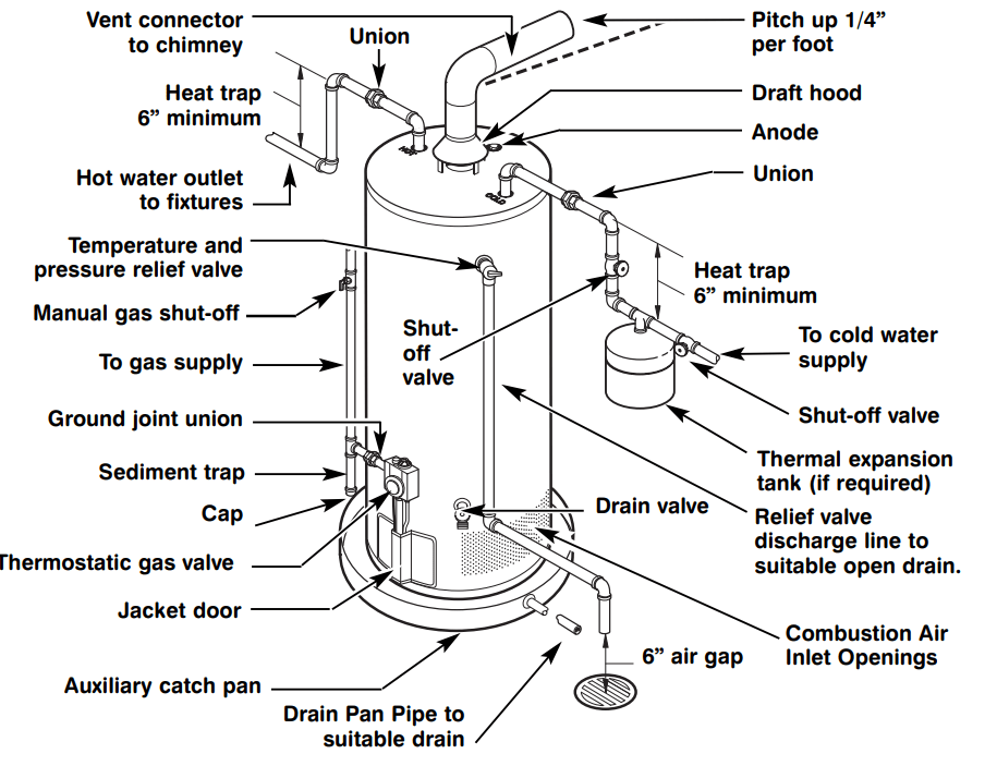
Refer to the illustration below for suggested typical installation. The installation of unions or flexible copper connectors is recommended on the hot and cold water connections so that the water heater may be easily disconnected for servicing if necessary. The HOT and COLD water connections are clearly marked and are 3/4” NPT on all models. Install a shut-off valve in the cold water line near the water heater.
Typical Installation
Relief Valve
The pressure rating of the relief valve must not exceed 150 PSI, the maximum working pressure of the water heater as marked on the rating plate.
The Btuh rating of the relief valve must equal or exceed the Btuh input of the water heater as marked on its rating plate.
Position the outlet of the relief valve above a suitable open drain to eliminate potential water damage. Piping used should be of a type approved for hot water distribution.
The discharge line must be no smaller than the outlet of the valve and must pitch downward from the valve to allow complete drainage (by gravity) of the relief valve and discharge line.
The end of the discharge line should not be threaded or concealed and should be protected from freezing. No valve of any type, restriction or reducer coupling should be installed in the discharge line.
To Fill the Water Heater
Make certain that drain valve is closed, then open the shut-off valve in the cold water supply line.
Open each hot water faucet slowly to allow the air to vent from the water heater and piping.
A steady flow of water from the hot water faucet(s) indicates a full water heater.
Leak Testing
The water heater and its gas connections must be leak tested at normal operating pressures before it is placed in operation.
Turn on the manual gas shut-off valve near the water heater.
Use a soapy water solution to test for leaks at all connections and fittings. Bubbles indicate a gas leak that must be corrected.
The factory connections to the thermostat should also be leak tested after the water heater is placed in operation.
Pressure Testing the Gas Supply System
The water heater and its manual gas shut-off valve must be disconnected from the gas supply piping system during any high pressure testing of that system at pressures in excess of 3/8 psi (10.5” w.c.) for natural gas, or 1/2 psi (14” w.c.) for LP gas.
The water heater must be isolated from the gas piping system by closing the manual gas shut-off valve during any pressure testing of the gas supply piping at pressures equal to or less than 3/8 psi (10.5” w.c.) for natural gas, or 1/2 psi (14” w.c.) for LP gas.
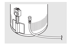
Hot and Cold Pipe Insulation Installation
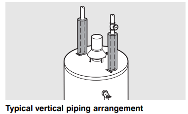
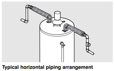
For increased energy efficiency, some water heaters have been supplied with two 24” sections of pipe insulation.
Please install the insulation, according to the illustrations above, that best meets your requirements.
Operating Instructions
Operating the water heater
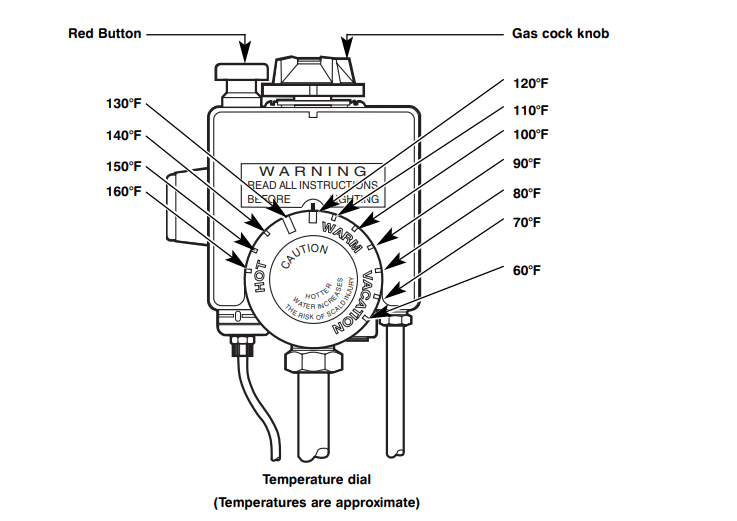
Water Temperature Setting
The temperature of the water in the water heater can be regulated by setting the temperature dial on the front of the gas control (thermostat).
Safety and energy conservation are factors to be considered when selecting the water temperature setting of the water heater’s gas control (thermostat(s)). The lower the temperature setting, the greater the savings in energy and operating costs
To comply with safety regulations the gas control (thermostat) was set at its lowest setting before the water heater was shipped from the factory. The recommended starting point temperature is 120°F.
Water temperatures above 125°F can cause severe burns or death from scalding. Be sure to read and follow the warnings outlined in this manual and on the label located on the water heater near the gas control (thermostat).
Mixing valves are available for reducing point of use water temperature by mixing hot and cold water in branch water lines. Contact a licensed plumber or the local plumbing authority for further information. (See page 4 for more details).
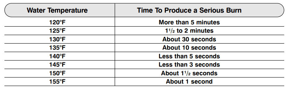
The chart below may be used as a guide in determining the proper water temperature for your home.
Time/Temperature Relationship in Scalds
Water Temperature Setting…
Maximum water temperatures occur just after the burner has shut off. To determine the water temperature, turn on a hot water faucet and place a thermometer in the water stream.
The wide reference mark near WARM on the rim of the temperature dial, represents an approximate water temperature of 120°F.
The long wide reference mark, to the left, represents an approximate water temperature of 130°F.
Each reference mark above or below these points indicates an approximate change of 10°F.
To adjust the temperature, turn the temperature dial to an initial setting of 120°F.
A condition known as “stacking” or “layering” can occur when a series of short and frequent hot water draws are taken.
The hottest temperature water will be at the top of the tank, closest to the outlet pipe delivering hot water to the home.
Stacking can cause this top layer of water to be hotter than the water toward the bottom of the tank near the gas control (thermostat)
Therefore, always remember to test the water temperature with your hand before use and remember that hotter water increases the risk of scald injury.
Also, always supervise young children or others who are incapacitated.
The gas control (thermostat) is constructed with a built in safety shut-off device designed to shut off the gas supply to the burner if the pilot flame is extinguished for any reason.
The gas control (thermostat) is also equipped with a single use gas shut off device that will shut off the gas supply to the burner if the water heater exceeds normal operating temperatures. Refer to the BEFORE YOU CALL FOR SERVICE section of this manual, or contact your dealer.
If the water heater has been subjected to fire, flood or physical damage, turn off the manual gas control (shut-off) valve, and do not operate the water heater again until it has been checked by qualified personnel.
NOTICE: Replace any part of the gas control system which has been under water.
Care and cleaning
Draining the Water Heater
In order to drain the water heater, turn off the cold water supply. Open a hot water faucet or lift the handle on the relief valve to admit air to the tank.
Attach a garden hose to the drain valve on the water heater and direct the stream of water to a drain. Open the valve.
Routine Preventative Maintenance
Properly maintained, your water heater will provide years of dependable trouble-free service.
It is recommended that a periodic inspection of the gas control (thermostat), burner, relief valve, internal flue-way and venting system should be made by service personnel qualified in gas appliance repair.
It is suggested that a routine preventative maintenance program be established and followed by the user.
At least once a year, lift and release the lever handle on the temperature pressure relief valve, located near the top of the water heater, to make certain the valve operates freely. Allow several gallons to flush through the discharge line to an open drain.
NOTICE: If the temperature and pressure relief valve on the hot water heater discharges periodically, this may be due to thermal expansion in a closed water system. Contact the water supplier or your plumbing contractor on how to correct this. DO NOT plug the relief valve outlet.
A water heater’s tank can act as a setling basin for solids suspended in the water. It is therefore not uncommon for hard water deposits to accumulate in the bottom of the tank. If allowed to accumulate, these solids can cover the gas control (thermostat) sensors, causing the sensors to operate erratically.
Because accumulated solids can prevent the gas control (thermostat) sensors from accurately reading the water temperature, the water at the fixture can be hotter than the gas control (thermostat) dial setting. It is suggested that a few quarts of water be drained from the water heater’s tank every month to clean the tank of these deposits.
Rapid closing of faucets or solenoid valves in automatic water using appliances can cause a banging noise heard in a water pipe. Strategically located risers in the water pipe system or water hammer arresting devices can be used to minimize the problem.
The anode rod should be removed from the water heater’s tank annually for inspection and replaced when more than 6” of core wire is exposed at either end of the rod.
Make sure the cold water supply is turned off before removing anode rod.
This water heater incorporates a combustion shut off device that shuts the operation of the water heater down if undesirable combustion conditions occur. Such as the presence of flammable vapors or blockage of the combustion air inlet openings. Please contact a Qualified Service Technician if this occurs
Housekeeping
Visually inspect pilot burner and relight if necessary.
To ensure sufficient ventilation and combustion air supply, proper clearances must be maintained.
When installed in a closet, DO NOT block or obstruct any of the combustion air inlet openings located around the perimeter of the water heater. A minimum of 1” is required between these combustion air inlet openings and any obstruction.
Venting System Inspection
The water heater’s internal flue must be inspected annually to be certain it is clean by removing the draft hood and flue baffle.
When reinstalling the flue baffle make certain it is hung securely by its hanger at the top of the flue way.
Reinstall the draft hood.
Inspect the gas venting system and the chimney.
Make certain the vent connector from the draft hood to the chimney is properly positioned and securely attached.
If after inspection of the vent system you found sooting or deterioration call the local gas utility to correct the problem and clean the flue, or replace the flue, flue baffle, and venting system before resuming operation of the water heater.
Test for spillage at the draft hood relief opening after 5 minutes of burner operation. Use a flame of a match or candle or smoke.
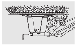
Burner Inspection
Proper burner and pilot flame pattern
Visually inspect the pilot and main burners annually.
Through the sight glass, inspect the pilot burner flame with main burner off and inspect the main burner while firing.
If any unusual burner operation is noted, the water heater should be shut off until qualified service assistance can be obtained.
For cleaning, remove the burner from the water heater. A vacuum cleaner can be used on the burner and floor shield inside the water heater.
The burner can also be cleaned by scrubbing with mild detergent.
Vacation and Extended Shut-Down
If the water heater is to remain idle for an extended period of time, the power and water to the appliance should be turned off to conserve energy and prevent a buildup of dangerous hydrogen gas.
The water heater and piping should be drained if they might be subjected to freezing temperatures.
After a long shut-down period, the water heater’s operation and controls should be checked by qualified service personnel. Make certain the water heater is completely filled again before placing it in operation.
Anode Rod
This water heater is equipped with an anode rod designed to prolong the life of the glass lined tank. The anode rod is slowly consumed, thereby eliminating or minimizing corrosion of the glass lined tank.
Water sometimes contains a high sulfate and/or mineral content and together with cathodic protection process can produce a hydrogen sulfide, or rotten egg odor in the heated water. Chlorination of the water supply should minimize the problem.
Troubleshooting Tips
This water heater incorporates a combustion shut-off device that shuts the operation of the water heater down if undesirable combustion conditions occur. Such as the presence of flammable vapors or blockage of the combustion air inlet openings. Please contact a Qualified Service Technician if this occurs.
Problem
Possible Causes
What To Do
Condensation
This usually happens when a new water heater is filled for the first time.
This is normal. After the water in the tank warms up the condensation will disappear. If, however, the condition persists, examine the piping and fittings for possible leaks.
Moisture from the products of combustion condensing on the tank surface.
This is normal and will disappear in time. Excessive condensation can cause pilot outage.
An undersized water heater will cause condensation
Use a water heater size that meets the requirements of your needs.
Yellow flame or soot
Scale on top of the burner.
Call a qualified service technician to remove scale.
Flue or combustion air inlet openings are restricted.
Remove obstruction or debris from flue or combustion air inlet openings on jacket.
Not enough combustion or ventilation air supplied to the water heater location.
Proper operation of the water heater requires air for combustion and ventilation. See the Combustion and Ventilation Air information in the “Installing The Water Heater” section of this manual.
Unable to light the pilot
Air in gas line
Contact a qualified service technician to purge the air from the gas line.
Pilot orifice clogged
The pilot should be cleaned or replaced by a qualified service technician.
Pilot tube pinched or clogged
The pilot should be cleaned, repaired or replaced by a qualified service technician.
Gas Cock Knob not correctly positioned.
See the “Lighting The Water Heater” section of this manual
Pilot does not stay lit when the RED button is released
Loose thermocouple.
The connection at the gas control (thermostat) should be tightened by a qualified service technician.
Thermocouple defective.
The thermocouple should be replaced by a qualified service technician.
Safety magnet defective.
The gas control (thermostat) should be replaced by a qualified service technician.
Gas control (thermostat)’s single use gas shut-off device has opened.
The gas control (thermostat) should be replaced by a qualified service technician.
Combustion Shutoff Device Tripped
The combustion shutoff device should be replaced by a qualified service technician
Rumbling noise
Scale and sediment in tank.
Clean tank.
Relief valve producing popping noise or draining
Pressure build up caused by thermal expansion to a closed system.
This is an unacceptable condition and must be corrected. Contact the water supplier or plumbing contractor on how to correct this. Do not plug the relief valve outlet.
Not enough or no hot water
Water usage may have exceeded the capacity of the water heater.
Wait for the water heater to recover after an abnormal demand
Low gas pressure.
Check gas supply pressure and manifold pressure.
The pilot may be out.
Check the pilot. If necessary, relight using the instructions in the “Lighting The Water Heater” section of this manual
may be set too low.The gas control (thermostat)
See the “Water Temperature Setting of The Water Heater” section of this manual.
Leaking or open hot water faucets
Make sure all faucets are closed.
Combustion Shutoff System tripped
Contact a qualified service technician.
Water is too hot
The gas control (thermostat) is set too high.
See the “Water Temperature Setting of The Water Heater” section of this manual.
Gas control (thermostat) Defective
Contact a qualified service technician to replace the gas control (thermostat).
Pilot Lights, but Burner will not stay lit
Combustion Shutoff System tripped
Contact a qualified service technician.
CAUTION: For your safety DO NOT attempt repair of gas piping, gas control (gas control (thermostat)), burners, vent connectors or other safety devices. Refer repairs to qualified service personnel.