Loading ...
Loading ...
Loading ...
7
Unpacking
Carton Contents
• Electric pressure washer
• Handle
• Trigger gun
• Spray wand assembly
• Adjustable spray wand nozzle
• Two (2) Phillips head screws (for handle)
• Cord holder
• Needle clean-out tool (included with manual packet)
• High-pressure hose
• Garden hose adapter (female coupler)
• Manuals with registration card
1. Carefully remove the pressure washer and check to see
that all of the above items are supplied.
2. Inspect the product carefully to make sure no breakage or
damage occurred during shipping. If you nd damaged or
missing parts, DO NOT return the unit to the store. Please
call the Snow Joe
®
+ Sun Joe
®
customer service center at
1-866-SNOWJOE (1-866-766-9563).
NOTE: Do not discard the shipping carton and packaging
material until you are ready to use your new electric
pressure washer. The packaging is made of recyclable
materials. Properly dispose of these materials in
accordance with local regulations.
IMPORTANT! The equipment and packaging material are
not toys. Do not let children play with plastic bags, foils,
or small parts. These items can be swallowed and pose a
suocation risk!
WARNING! Do not connect to power supply until assembly
is complete. Failure to comply could result in accidental
starting and possible serious personal injury.
Assembly
Tools required: Phillips head screwdriver
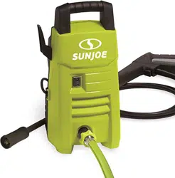
1. Following the alignment grooves at the top of the machine
body, slide the handle into position from the front to the
back, so that the solid side of the handle faces the front
of the washer. Secure the handle using a Phillips head
screwdriver and the two (2) supplied Phillips head screws
(Fig. 1).
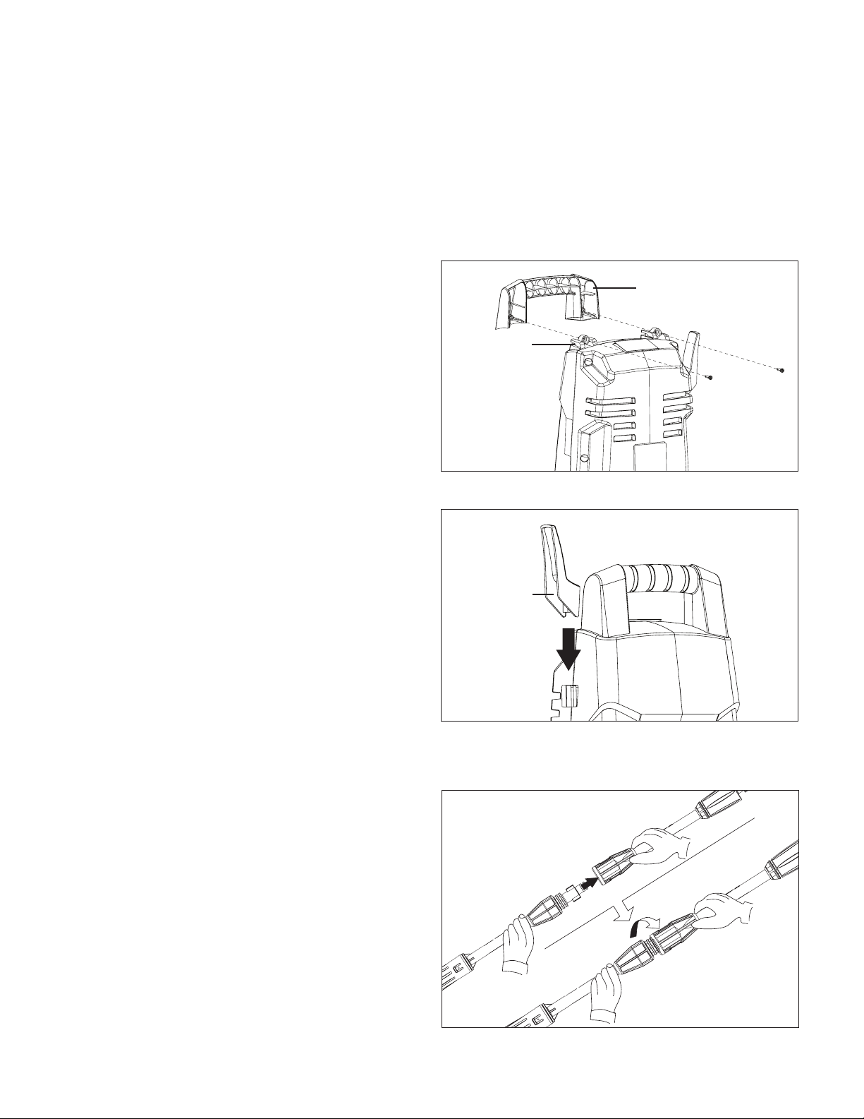
2. Slide the cord holder into position (Fig. 2).
3. Fit the two pieces of the spray wand assembly together
and rotate it until the two parts are completely locked
(Fig. 3).
Fig. 1
Handle
Alignment
grooves
Fig. 2
Cord holder
Fig. 3
Loading ...
Loading ...
Loading ...