Use, Care, and Installation Guide
www.zephyronline.com
Model number:
Serial Number:
Date of Purchase:
Sales Dealer:
JUL20.0401 © Zephyr Ventilation LLC.
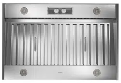
Spruce
AK9834AS
AK9840AS
AK9846AS
AK9858AS
READ AND SAVE THESE INSTRUCTIONS
INTENDED FOR OUTDOOR COVERED PATIO OR LANAI AREA.

www.zephyronline.com

1
SAFETY NOTICE .......................................................................... 2-3
LIST OF MATERIALS
................................................................. 4
INSTALLATION
Ducting Calculation Sheet
....................................... 5
Mounting Height & Clearance
................................ 6
Ducting Options
........................................................... 7
Specications
............................................................... 8
Electrical
......................................................................... 9
Installing the One Piece Insert
.............................. 10
Insert Preparation
....................................................... 11
FEATURES & CONTROLS
Rotary Controls
............................................................ 12
MAINTENANCE
Cleaning & Installing Filters
.................................... 13
Lights & Parts List
....................................................... 14
WIRING DIAGRAM
...................................................................... 15
TROUBLESHOOTING
................................................................ 16
WARRANTY
.................................................................................... 17
PRODUCT REGISTRATION
.................................................... 18
Table of Contents

Important Safety Notice
READ AND SAVE THESE INSTRUCTIONS
2
www.zephyronline.com
WARNING
TO REDUCE THE RISK OF FIRE OR ELECTRIC SHOCK, DO NOT USE THIS FAN WITH ANY SOLID-STATE CONTROL DEVICE.
WARNING
TO REDUCE THE RISK OF FIRE ELECTRIC SHOCK, OR INJURY TO PERSONS, OBSERVE THE FOLLOWING:
a. Use this unit only in the manner intended by the manufacturer, if you have questions, contact the manufacturer.
b. Beforeservicingorcleaningunit,switchpoweroatservicepanelandlockpaneltopreventpowerfrombeingswitchedonaccidentally.
Whentheservicedisconnectingmeanscannotbelocked,securelyfastenaprominentwarningdevice,suchasatag,totheservice
panel.
c. This unit must be grounded and protected by a GFCI.
d. Suitable for use in damp locations only when installed in a GFCI PROTECTED branch-circuit.
CAUTION
Forgeneralventilatinguseonly.Donotusetoexhausthazardousorexplosivematerialsandvapors.Takecarewhenusingcleaning
agentsordetergents.Suitableforuseinhouseholdcookingarea.
WARNING
TO REDUCE THE RISK OF RANGE TOP GREASE FIRE:
a. Neverleavesurfaceunitsunattendedathighsettings.Boiloverscausesmokingandgreasyspilloversthatmayignite.Heatoilsslowly
on low or medium settings.
b. AlwaysturnhoodONwhencookingathighheatorwhenamingfood
c. Cleanventilatingfansfrequently.Greaseshouldnotbeallowedtoaccumulateonfanorlter.
d. Useproperpansize.Alwaysusecookwareappropriateforthesizeofthesurfaceelement.
e. Keepfan,ltersandgreaseladensurfacesclean.
f. Use high setting on hood only when necessary.
g. Don’tleavehoodunattendedwhencooking.
h. Alwaysusecookwareandutensilsappropriateforthetypeofandamountoffoodbeingprepared.
WARNING
TO REDUCE THE RISK OF INJURY TO PERSONS IN THE EVENT OF A RANGE TOP FIRE, OBSERVE THE FOLLOWING:
a. SMOTHERFLAMESwithaclose-ttinglid,cookiesheet,ormetaltray,thenturnotheburner.BECAREFULTOPREVENTBURNS.
Iftheamesdonotgooutimmediately,EVACUATEANDCALLTHEFIREDEPARTMENT.
b. NEVER PICK UP A FLAMING PAN – You may be burned.
c. DO NOT USE WATER, including wet dishcloths or towels – a violent steam explosion will result.
d. Use an extinguisher ONLY if:
1. YouknowyouhaveaClassABCextinguisher,andyoualreadyknowhowtooperateit.
2. Thereissmallandcontainedintheareawhereitstarted.
3. Theredepartmentisbeingcalled.
4. Youcanghttherewithyourbacktoanexit
WARNING
TO REDUCE THE RISK OF FIRE, ELECTRIC SHOCK OR INJURY TO PERSONS, OBSERVE THE FOLLOWING:
a. Installationworkandelectricalwiringmustbedonebyqualiedperson(s)inaccordancewithallapplicablecodesandstandards.
Includingre-ratedconstruction.
b. Sucientairisneededforpowercombustionandexhaustingofgasesthroughtheue(chimney)offuelburningequipmenttoprevent
back-drafting.Followtheheatingequipmentmanufacturer’sguidelineandsafetystandardssuchasthosepublishedbytheNational
FireProtectionAssociation(NFPA)andtheAmericanSocietyforHeating,RefrigerationandAirConditioningEngineers(ASHRAE)and
the local code authorities.
c. When cutting or drilling into wall or ceiling, do not damage electrical wiring and other hidden utilities.
d. Ducted fans must always vent to the outdoors.
e. NEVER place a switch where it can be reached from a tub or shower.
f. Makesurethepowerisobeforeinstalling,wiringormaintenancing.

Important Safety Notice
3
WARNING
TO REDUCE THE RISK OF FIRE, USE ONLY METAL DUCTWORK.
CAUTION
Toreduceriskofreandtoproperlyexhaustairoutside-Donotventexhaustairintospaceswithinwalls,ceilings,
attics, crawl spaces or garages.
OPERATION
Alwaysleavesafetygrillesandltersinplace.Withoutthesecomponents,operatingblowerscouldcatchontohair,ngers
and loose clothing.
The manufacturer declines all responsibility in the event of failure to observe the instructions given here for installation,
maintenance and suitable use of the product. The manufacturer further declines all responsibility for injury due to
negligence and the warranty of the unit automatically expires due to improper maintenance.
*NOTE: Please check www.zephyronline.com for revisions before doing any custom work.
ELECTRICAL REQUIREMENTS
Important:
Observe all governing codes and ordinances.
It is the customer’s responsibility:
- Tocontactaqualiedelectricalinstaller.
- To assure that the electrical installation is adequate and in conformance with National Electrical Code, ANSI/NFPA 70
latest edition* or CSA standards C22.1-94, Canadian Electrical Code, Part 1 and C22.2 No.0-M91 - latest edition** and
all local codes and ordinances.
Ifcodespermitandaseparategroundwireisused,itisrecommendedthataqualiedelectriciandeterminethatthe
ground path is adequate.
Do not ground to a gas pipe.
Checkwithaqualiedelectricianifyouarenotsuretherangehoodisproperlygrounded.
Do not have a fuse in the neutral or ground circuit.
*NationalFireProtectionAssociationBatterymarchPark,Quincy,Massachusetts02269
** CSA International 8501 East Pleasant Valley Road, Cleveland, Ohio 44131-5575
This appliance requires a 120V 60Hz electrical supply and connected to an individual properly grounded branch circuit
protectedbya15or20amperecircuitbreakerortimedelayfuse.Wiringmustbe2wirewithground.Pleasealsoreferto
Electrical Diagram on product.
Acablelockingconnector(notsupplied)mightalsoberequiredbylocalcodes.Checkwithlocalrequirements,purchase
and install appropriate connector if necessary.
INTENDED FOR OUTDOOR COVERED PATIO OR LANAI AREA.
SUITABLE FOR USE IN DAMP LOCATIONS WHEN INSTALLED IN A GFCI PROTECTED BRANCH-CIRCUIT.
Cancer and Reproductive Harm - www.P65Warnings.ca.gov
WARNING:
Prop. 65 Warning for California Residents
List of Materials
4
www.zephyronline.com
MODELS: AK9834AS, AK9840AS, AK9846AS AND AK9858AS
PARTS SUPPLIED
1 - Insert hood body
2-Baelters(3forAK9846AS&AK9858AS)
4-Halogenlightbulbs(pre-installed)
1-Dualinternalblower(pre-installed)
1 - 10” round duct collar
1-Hardwarepackage
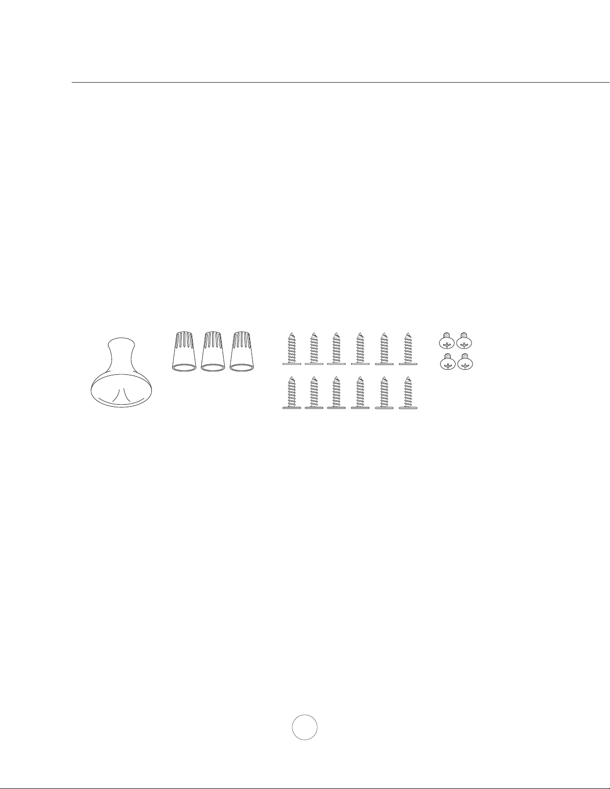
HARDWARE PACKAGE CONTENTS
PARTS NOT SUPPLIED
- Ducting, conduit and all installation tools
- Cable connector (if required by local codes)
Light Bulb Removal
Suction Cup (1)
M4 x 6mm (4)
Wire Caps (3)
#8 x 1/2” (12)
RF Remote Control (1) Remote Holder (1)
5
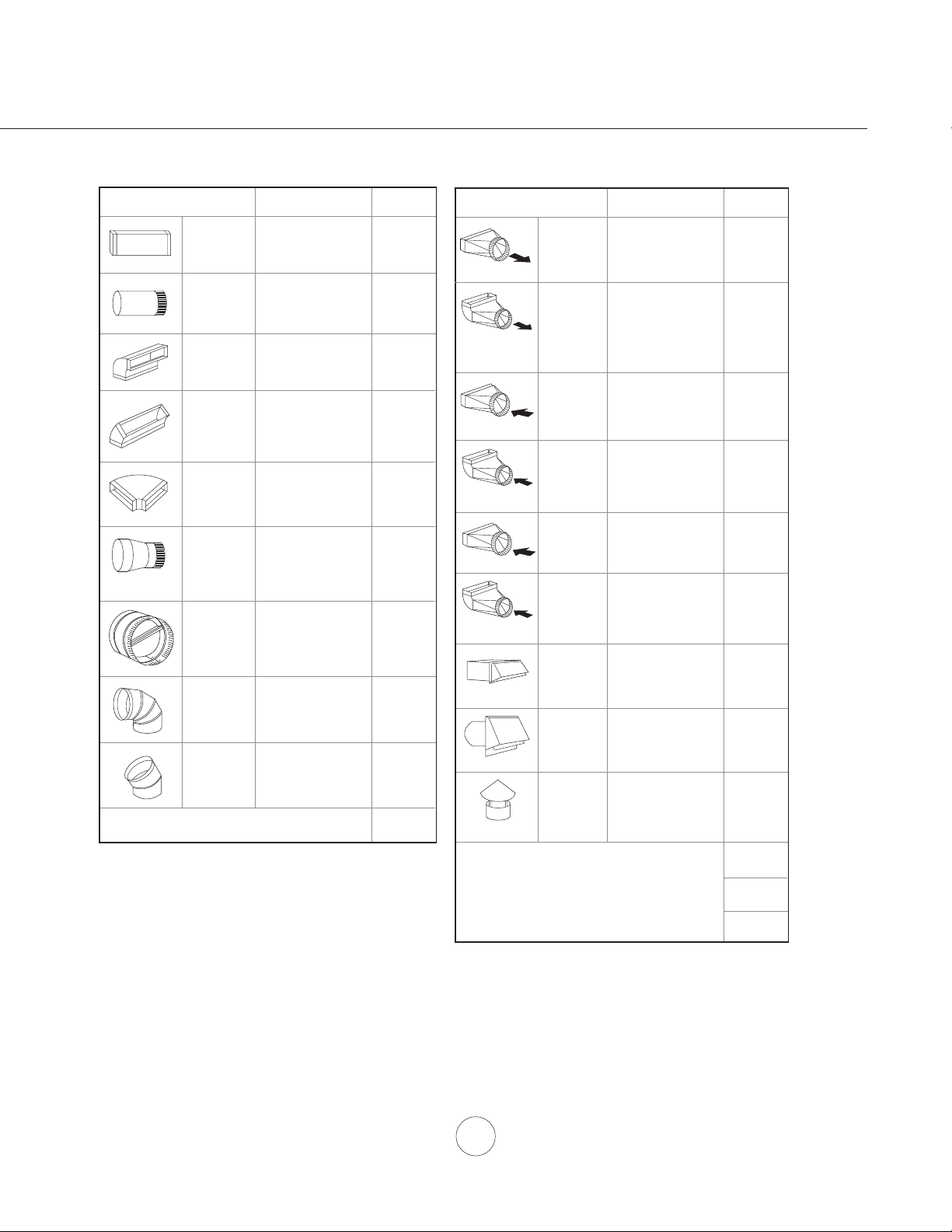
Installation – Ducting Calculation Sheet
Duct pieces
To tal
Equivalent number
length x used =
3- 1/ 4” x 10”
Rect.,
straight
1 Ft. x ( ) =
Ft.
3- 1/ 4” x 10”
Rect. to
6” round
transition
5 Ft. x ( ) =
Ft.
3- 1/ 4” x 10”
Rect. to
6” round
transition
90
0
elbow
20 Ft. x ( ) =
Ft.
6”, 7”, 8”, 10”
Round,
90
0
15 Ft.
x ( ) =
Ft.
6”, 7”, 8”, 10”
Round,
45
0
9 Ft. x ( ) =
Ft.
Ft.
6”, 7”, 8”, 10”
Round,
straight
1 Ft. x ( ) =
Ft.
Subtotal column 1 =
Duct pieces
To tal
Equivalent number
length x used =
6”, 7”, 8”, 10”
Round, wall
cap with
damper
30 Ft. x ( ) =
Ft.
Ft.
Ft.
Ft.
6”, 7”, 8”, 10”
Round
roof cap
30 Ft. x ( ) =
Ft.
Subtotal column 2 =
Subtotal column 1 =
Total ductwork =
Maximum Duct Length: For satisfactory air movement,
the total duct length
should not exceed 100 equivalent feet.
6” round to
3- 1/ 4” x 10”
rect.
transition
1 Ft. x ( ) =
Ft.
6” round to
3- 1/ 4” x 10”
rect.
transition
90
0
elbow
16 Ft. x ( ) =
Ft.
7” round to
3 1/ 4” x 10”
rect.
transition
8 Ft. x ( ) =
Ft.
7” round to
3- 1/ 4” x 10”
rect.
transition
90
0
elbow
23 Ft. x ( ) =
Ft.
elbow
elbow
7” to 6” or
8” to 7” Round
tapered
reducer
25 Ft. x ( ) =
Ft.
3- 1/ 4” x 10”
Rect. 90
0
elbow
15 Ft. x ( ) =
Ft.
3- 1/ 4” x 10”
Rect. 45
0
elbow
9 Ft. x ( ) =
Ft.
3- 1/ 4” x 10”
Rect. 90
0
flat elbow
24 Ft. x ( ) =
Ft.
3- 1/ 4” x 10”
Rect.
wall cap
with damper
30 Ft. x ( ) =
Ft.
Ft. x ( ) =
Ft.
15
6”, 7“, 8”
Round
in-line
damper
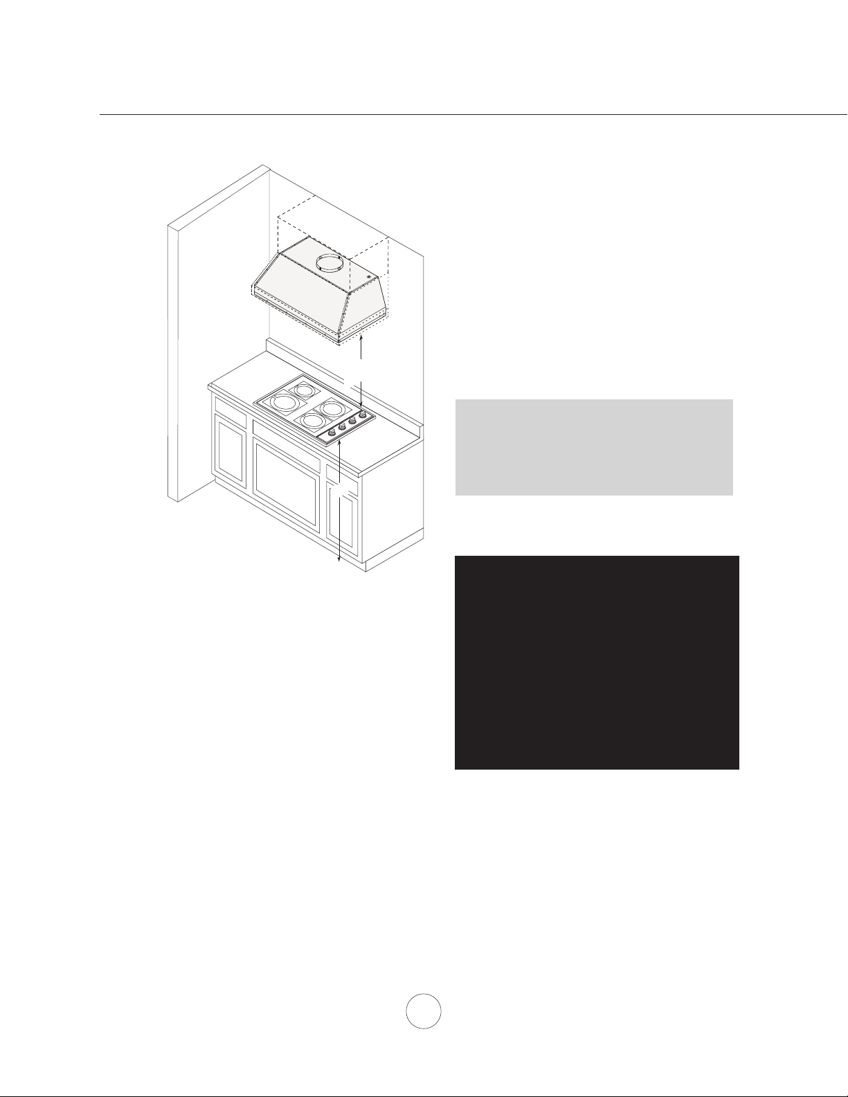
Installation – Mounting Height & Clearance
6
www.zephyronline.com
DUCTING
A minimum of 10” round duct must be used to
maintainmaximumairoweciency.
Always use rigid type metal ducts only. Flexible
ductscouldrestrictairowbyupto50%.
Alsousecalculation(onpage5)tocomputetotal
available duct run when using elbows, transitions
and caps.
ALWAYS, when possible, reduce the number or
transitions and turns. If long duct run is required,
increase duct size.
If turns or transitions are required; install as far
away from hood duct output and as far apart,
between the two as possible.
Minimum mount height between range top to hood
bottom should be no less than 30”.
Maximum mount height should be no higher than
36”.
It is important to install the hood at the proper
mounting height. Hoods mounted too low could
resultinheatdamageandrehazard;whilehoods
mounted too high will be hard to reach and will
loseitsperformanceandeciency.
If available, also refer range manufacturer’s height
clearance requirements and recommended hood
mounting height above range.
Vertical Ducting:
10” round minimum
Horizontal Ducting:
N/A
DAMAGE-SHIPMENT / INSTALLATION:
• Please fully inspect unit for damage before
installation.
• If the unit is damaged in shipment, return the
unit to the store in which it was bought for
repair or replacement.
• If the unit is damaged by the customer, repair
or replacement is the responsibility of the
customer.
• Iftheunitisdamagedbytheinstaller(ifother
thanthecustomer),repairofreplacementmust
be made by arrangement between customer
and installer.
30” min.
36” max.
36”
7
WARNING FIRE HAZARD
NEVERexhaustairorterminateductworkintospacesbetweenwalls,crawlspaces,ceiling,atticsorgarages.
All exhaust must be ducted to the outside.
Usesinglewallrigidmetalductworkonly.
FastenallconnectionswithsheetmetalscrewsandtapealljointswithcertiedSilverTapeorDuctTape.
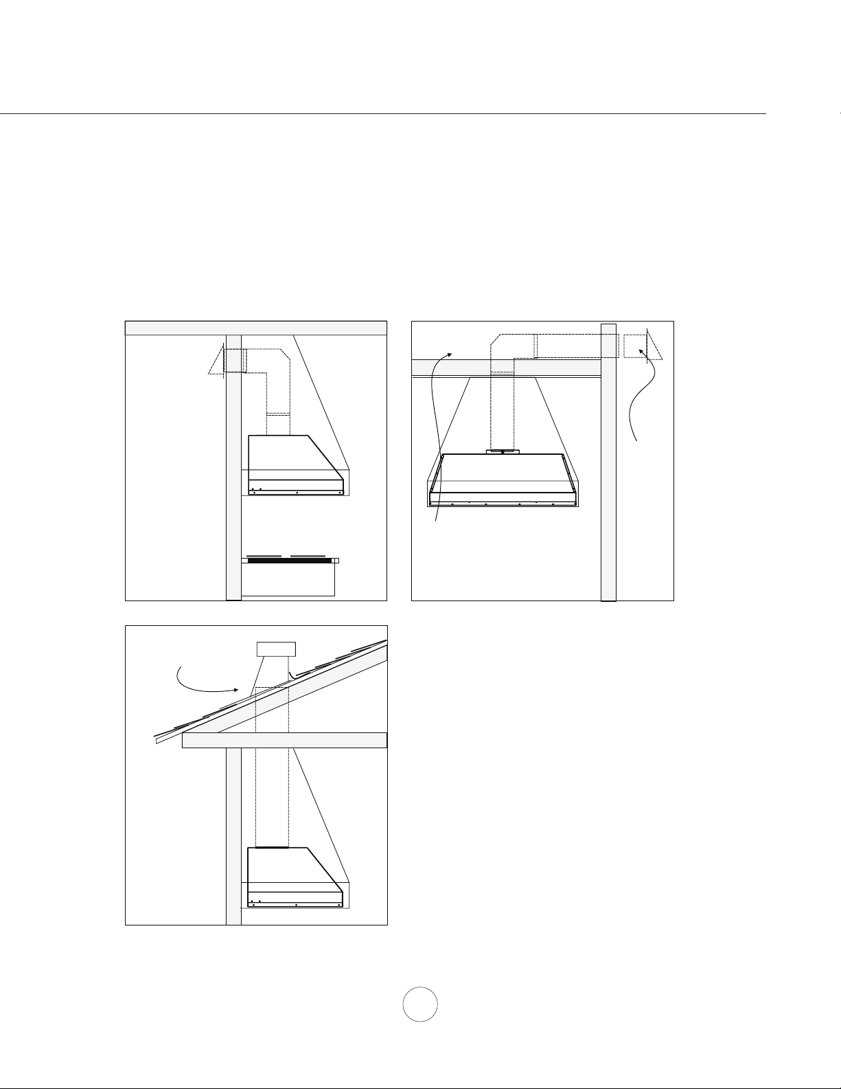
Some Ducting Options
Installation – Ducting Options
side wall cap
w/ gravity damper
side wall cap
w/ gravity damper
Soffit or crawl space
Roof Pitch w/
Flashing & Cap
8
www.zephyronline.com
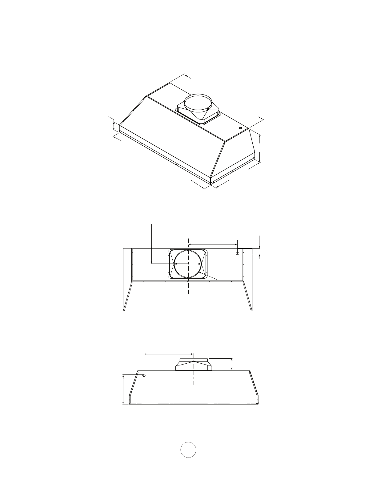
Installation – Specications
Top View
3/4 View
Back View
34-
3/8”,
40-
3/8
”, 46-
3/8
”
3”
12”
28-
3/8”
, 34-
3/8
”, 40-
3/8
”
2
2
-
1
/2
”
5-
5/8
”
C/L
Ø
1
0
”
(34”)12”
(40”)15”
(46“)18”
(58”)27”
2”
elec.
k/o
C/L
10-
3/8
”
(34”)12”
(40”)15”
(46“)18”
(58”)27”
4-
3/8
”
elec.
k/o
, 52-
3/8”
,
5
8-
7/8
”
9
ELECTRICAL
WARNING
All Electrical work must be performed by qualied electrician or person with similar technical know
how and background.
Forpersonalsafety,removehousefuseoropencircuitbreakerbeforebeginninginstallation.Donotuse
extension cord or adapter plug with this appliance.
Follow national electrical codes or prevailing local codes and ordinances.
Electrical Supply:
This appliance requires a 120V 60Hz electrical supply, and connected to an individual, properly grounded
branchcircuit,protectedbya15or20amperecircuitbreakerortimedelayfuse.Wiringmustbe2wirew/
ground. Please also refer Electrical Diagram labeled on product.
Cable Lock:
Acablelockingconnector(notsupplied)mightalsoberequiredbylocalcodes.Checkwithlocalrequirements
and codes, purchase and install appropriate connector if necessary.
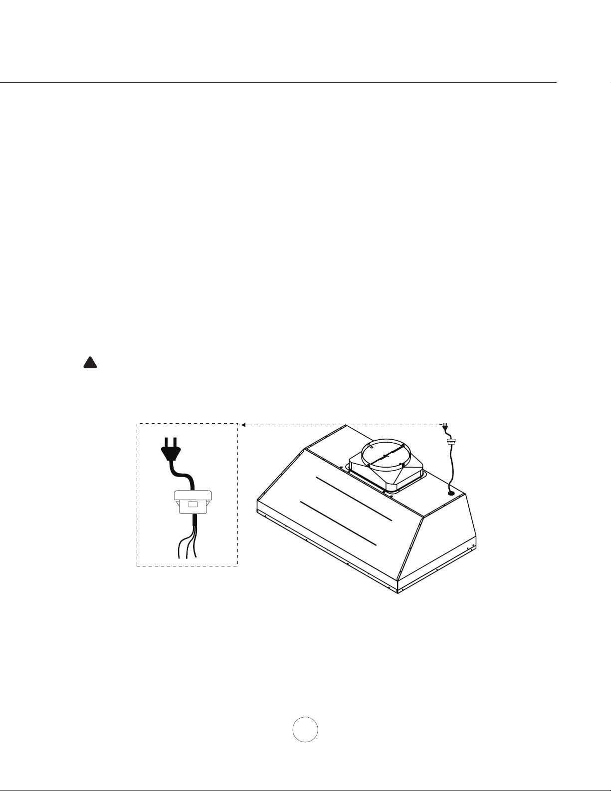
Installation – Electrical
Cable Lock
CAUTION: This unit must be grounded and protected by a GFCI.
Suitable for use in damp locations only when installed in a GFCI PROTECTED branch-circuit.
!

10
www.zephyronline.com
Installation – Installing the One Piece Insert
1.Removeallpackingmaterialsandprotectivelmpriortoinstallation.
Use caution during installation to prevent scratches or damage to the
stainless steel.
2. Cut out an opening in the bottom of the cabinet by following the
dimensions in FIG. 1.
3. Prepare insert for installation into cabinet by following the steps on
page 11.
4. Lift insert into bottom opening of cabinet and secure to interior of
cabinetusing(8)#8x1/2”stainlesssteelscrews;(4)screwsinthe
frontand(4)screwsinthesides.SeeFIG.2.
WARNING: Make sure the surface you are securing the insert to
is capable of holding the weight of AK98. Failure to do so may
cause personal injury or damage to cooking surface or counter.
5. Finalizeinstallationofelectricalandductwork.Sealductworkwith
certiedaluminumducttape.Poweroninsert,checkforleaksaround
duct tape and verify proper operation.
NOTE: If access to top of insert is not available after installation,
electricalandductworkconnectionmayneedtobemadepriorto
installing the insert.
6. Re-install the previously removed bottom panel, side spacer panels,
greasetray,andbaelters.
CAUTION: At least two installers ar
e
required
due to the weight and size of
the
hood.
!
FIG 1
FIG 2
34-1/2” or 40-1/2” or 46-1/2”
22-
5/
8
”
1-
1/8
”
1-
9/16
”
7/8
”
2-
1/2
”
1/4
”
5-
1/2
”
or
Front Mount Screw Dimensions
Side Mount Screw Dimensions
cut
ou
t
(AK9834)
(AK9846)
(AK9840)
7-
7/8
”
11-
7/8
”
or
7-
7/8
”
11-
7/8
”
or
7-
7/8
”
11-
7/8
”
or
or 59”
(AK9858)
If possible, power up and test all functions prior to installation.
1/4”
1-
1/8
”
FIG. 2
FIG. 1
11
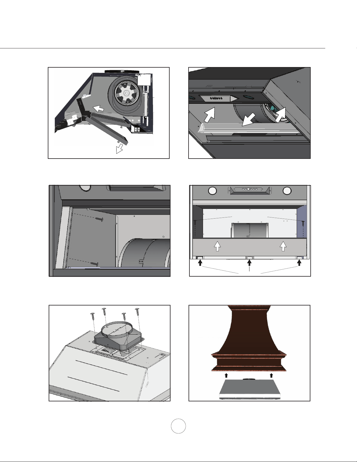
1.Removebaeltersby:1)Pullingltertoward
front of insert. 2)Pivotingrearoflterdown.
2. Remove grease tray by: 1) Pulling up on tray to
release from bottom panel. 2) Lifting tray out of
insert body.
3. Remove left and right side spacer panels by
removing(2)screwsfrombehindeachpanel.
Installation – Insert Preparation
1
2
1 1
2
Locking Tabs
Bottom Panel Screws
2 2
1
4. Remove bottom panel by: 1)Removing(2)
screws from left and right sides of bottom panel.
2) Pulling bottom panel toward front of insert to
releasefromlockingtabs.
6. Hood preperation is complete. Refer to page 10,
step 4 to complete installation.
5. Secure 10” round ducting collar to top of insert by
(4)M4x6mmscrews.
12
www.zephyronline.com
OFF
OFF
OFF
1
2
3
1
2
1
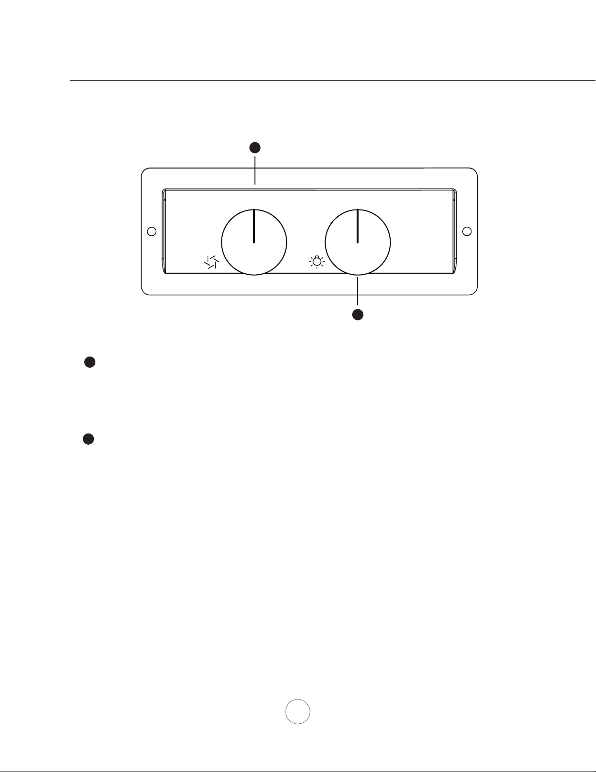
1
Blower On/Off/Speed Selection
2
2
Lights Dim/Bright/Off
1
1
Blower On/Off/Speed Selection
2
2
Lights Dim/Bright/Off
Rotate dial to change speed levels, (1) for low speed, (2) for medium speed and (3) for high speed
Rotate dial to change light settings, (1) for dim light and (2) for bright light
Controls – Rotary Controls
13
SURFACE MAINTENANCE:
Do not use corrosive detergents, abrasive detergents or oven cleaners.
Do not use any product containing chlorine bleach or any product containing chloride.
Do not use steel wool or abrasive scrubbing pads which will scratch and damage surface.
Cleaning Stainless Steel
Clean periodically with warm soapy water and clean cotton cloth or micro fiber cloth. Always rub in the
direction of the stainless steel grain. To remove heavier grease build up use a liquid degreaser detergent.
Aftercleaninguseanon-abrasivestainlesssteelpolish/cleaners,topolishandbuoutthestainlessluster
andgrain.Alwaysscrublightly,withcleancottonclothormicroberclothandbuinthedirectionofthe
stainless steel grain.
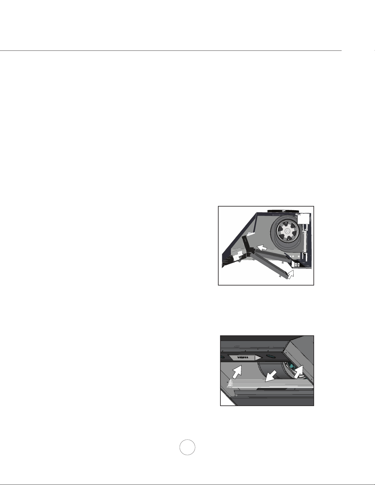
Cleaning the Bae Filters
Theltersareintendedtotrapresidueandgreasefromcooking.Althoughtheltersshouldneverneed
replacing,theyarerequiredtobecleanedevery30daysormoreoftendependingoncookinghabits.
FiltersmaybeplacedindishwasheratlowheatorsoakedinhotsoapywaterDryltersandre-installbefore
using hood.
Installing the Bae FIlters, FIG 5:
1. Placelterintotopgrooveoftheinsertasshownand
pull towards front of insert using handles.
2. Pivotbackoflterupwardssoitisangledintheinsert.
3.Pushlterintochannelonbackofinserttolockintoplace.
Cleaning the Grease Tray
Thegreasetrayisintendedtocatchresidueandgreasethatmaydripfromthebaelters.Thegreasetray
shouldbecleanedwhenbaeltersarecleaned.Cleanthegreasetraybysoakinginhotsoapywaterand
gentlyscrubinganyresidueowithasoftterrycloth.Drygreasetrayandre-installbeforeusinghood.
Removing the Grease Tray
Greasetrayhasahookedlipthatattachestobottompaneltopedge.
Remove grease tray by:
1. Pull up on tray to release from bottom panel. FIG. 6-1
2. Pull tray out of insert body. FIG. 6-2
1
2
Maintenance – Cleaning & Installing Filters
1 1
2
FIG. 5
FIG. 6
14
www.zephyronline.com
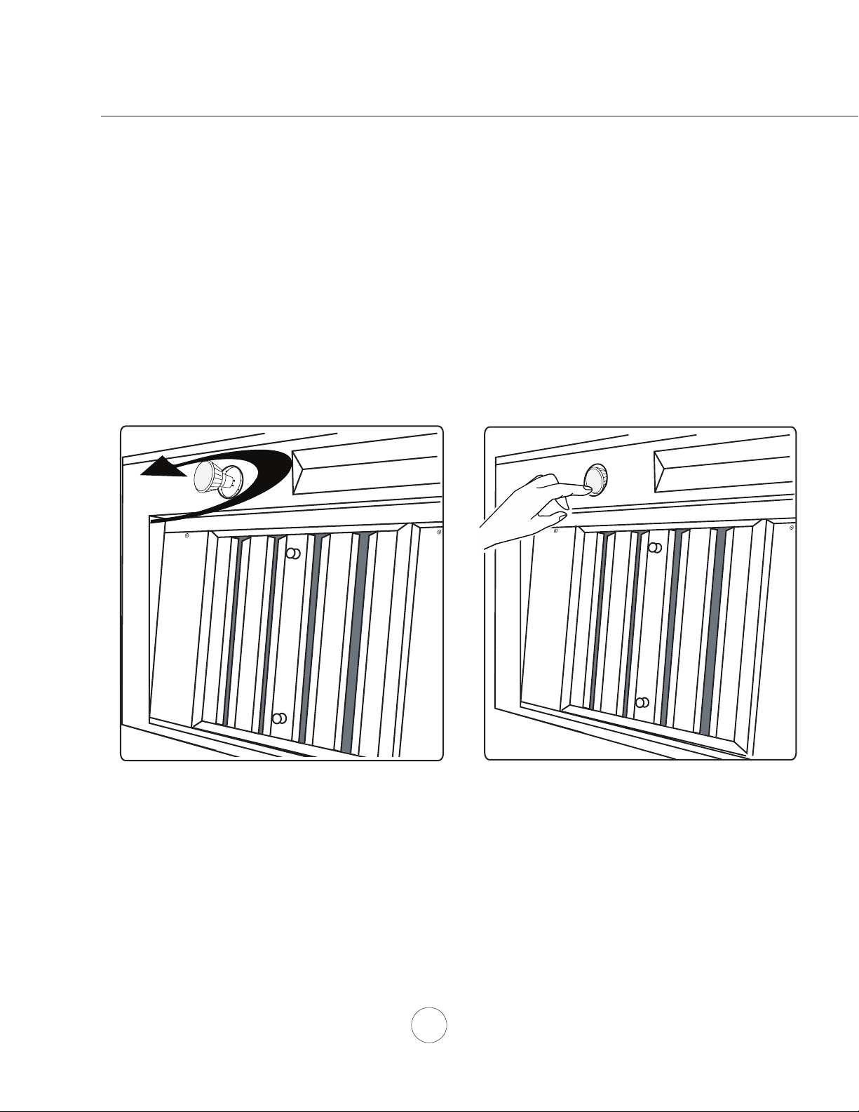
REPLACING LIGHT BULBS
CAUTION: Light bulb becomes extremely hot when turned on.
DO NOT touch bulb until switched o and cooled. Touching hot bulbs could cause serious burns.
Makesureallpoweristurnedoandbulbsarenothot.
Removebyturningbulbcounterclockwise.FIG7.Note: Bulb does not unscrew; it turns 60 degrees, stops and falls out.
Ifbulbsarediculttoturnduetoprolongeduse,rmlyattachtheglasssuctioncupprovidedtothebulborusearubber/
latexgloveandturncounterclockwise.
Directional Lighting
Thelightbulbscanbetiltedforwardsandbackwardstobetterdirectlightoveryourcookingsurface.FIG8.
WARNING: Only direct the bulbs when they are cool to the touch.
Maintenance – Lights, Parts List
REPLACEMENT PARTS
DESCRIPTION PART #
LightBulbMR16(GU10)35W(each) Z0B0023
OptionalLEDLightBulb(GU10)6W(each) Z0B0040
P r o B a e F i l t e r ( e a c h ) 5 0 2 1 0 0 3 1
To order parts, visit us online at http://store.zephyronline.com or call us at 1.888.880.8368
FIG. 7 FIG. 8
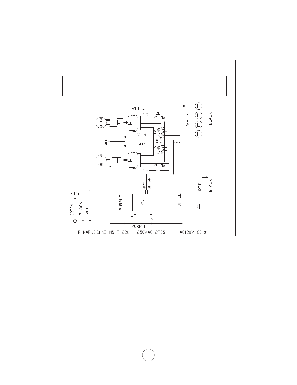
15
USE ONLY TYPE MR16, GU10, 35W. MAX. HALOGEN LIGHT BULBS.
AK9834AS, AK9840AS
AK9846AS, AK9858AS
VOLTS HZ MAX AMPS
120 60
Dual Motor 9
CIRCUIT DIAGRAM
2 A
B 3 4
2 A
B 3 4
Wiring Diagram

16
www.zephyronline.com
Troubleshooting
TROUBLESHOOTING PROCEDURES FOR SPRUCE
Issue Cause What to do
After installation,
the unit doesn’t
work.
1. The power source is not turned ON. 1. Makesurethecircuitbreakerandtheunit’s
power is ON.
2. Thepowerlineandthecablelockingconnector
is not connecting properly.
2. Checkthepowerconnectionwiththeunitis
connected properly.
3. The switch board and control board wirings are
disconnected.
3. Makesurethewiringsbetweentheswitch
board and control board are connected
properly.
4. The wires on control board are loose. 4. Makesurethewiresonthecontrolboardare
connected properly.
5. The switch board or control board is defective. 5. Change the switch board or control board.
Lightworks,but
blower is not
turning.
1. The blower wire is not connected. 1. Makesuretheblowerwireispluggedintothe
molex connector.
2. The thermally protected system detects if the
blower is too hot to operate and shuts the blower
down.
2. The blower will function properly after the
thermally protected system cool down.
3. Damaged capacitor. 3. Change the capacitor.
4.Blowermolexplugpinisnotmakingcontact. 4.Disconnecttheblowermolexplug,checkpins
inside plug to see if pin is pushed inside plug
too far. Reseat pin if needed.
5. The blower is defective, possibly seized. 5. Change the blower.
The unit is
vibrating.
1. The blower is not secure in place. 1. Tighten the blower in place.
2. The hood is not secured in place. 2. Checktheinstallationofthehood.
3. Damaged blower wheel. 3. Change the blower.
The unit is
whistling.
1.Thelterisnotinthecorrectposition. 1.Adjusttheltersuntilthewhilstlingstops.
2. The duct pipe connections are not sealed or
connected properly.
2.Checktheductpipeconnectionstobesureall
connections are sealed properly.
The blower is
working,butthe
lights are not.
1. Defective halogen bulb. 1. Change the halogen bulb.
2. The light bulb is loose. 2. Tighten the light bulb.
3. The light bulb plug is disconnected. 3. Connect the light bulb plug.
The hood is
not venting out
properly.
1. The hood might be hanging too high from the
cooktop.
1. Adjustthedistancebetweenthecooktopand
the bottom of the hood within 30” and 36”
range.
2. The wind from the opened windows or opened
doorsinthesurroundingareaareaectingthe
ventilation of the hood.
2. Close all the windows and doors to eliminate
theoutsidewindow.
3. Blockageintheductopeningorductwork. 3. Removealltheblockingfromtheductworkor
duct opening.
4. The direction of duct opening is against the wind. 4. Adjust the duct opening direction.
5. Using the wrong size of ducting. 5. Change the ducting to correct size.
Filter is vibrating. 1. Filter is loose. 1. Adjustorchangethelter.
2. Springclipisbrokeninsidelteropening. 2. Change the spring clip.
17
Warranty
OCT17.0301
ZephyrVentilation,LLC(referredtohereinas“we”or“us”)warrantstotheoriginalconsumerpurchaser(referredtoherein
as “you” or “your”) of Zephyr products (the “Products”) that such Products will be free from defects in materials or
workmanshipasfollows:
Three Year Limited Warranty for Parts: For three years from the date of your original purchase of the Products, we will
provide, free of charge, Products or parts (including LED light bulbs, if applicable) to replace those that failed due to
manufacturing defects subject to the exclusions and limitations below. We may choose, in our sole discretion, to repair or
replace parts before we elect to replace the Products.
One Year Limited Warranty for Labor: For one year from the date of your original purchase of the Products, we will
provide, free of charge, the labor cost associated with repairing the Products or parts to replace those that failed due to
manufacturing defects subject to the exclusions and limitations below. After the first year from the date of your original
purchase, you are responsible for all labor costs associated with this warranty.
Warranty Exclusions: This warranty covers only repair or replacement, at our option, of defective Products or parts and
does not cover any other costs related totheProductsincludingbutnotlimitedto:(a)normalmaintenanceandservice
required for the Products and consumable parts such as fluorescent, incandescent or halogen light bulbs, mesh and char-
coalfiltersandfuses;(b)anyProductsorpartswhichhave been subject to freight damage, misuse, negligence, accident,
faulty installation or installation contrary to recommended installationinstructions,impropermaintenanceorrepair(other
thanbyus);(c)commercialorgovernmentuseoftheProductsoruseotherwiseinconsistentwithitsintendedpurpose;(d)
natural wear of the finish of the Products or wear caused by improper maintenance, use of corrosive and abrasive cleaning
products, pads, and oven cleanerproducts;(e)chips,dentsorcrackscausedbyabuseormisuseoftheProducts;(f)service
trips to your home to teach you how to usetheProducts;(g)damagetotheProductscausedbyaccident,fire,floods,acts
ofGod;or(h)Custominstallations or alterations that impact serviceability of the Products. If you are outside our service
area, additional charges may apply for shipping costs for warranty repair at our designated service locations and for the
travel cost to have a service technician come to your home to repair, remove or reinstall the Products. After the first year
from the date of your original purchase, you are also responsible for all labor costs associated with this warranty. All Products
must be installed by a qualified professional installer to be eligible for warranty repairs or service.
Limitations of Warranty. OUR OBLIGATION TO REPAIR OR REPLACE, AT OUR OPTION, SHALL BE YOUR SOLE
AND EXCLUSIVE REMEDY UNDER THIS WARRANTY. WE SHALL NOT BE LIABLE FOR INCIDENTAL,
CONSEQUENTIAL OR SPECIAL DAMAGES ARISING OUT OF OR IN CONNECTION WITH THE USE OR
PERFORMANCE OF THE PRODUCTS. THE EXPRESS WARRANTIES IN THE PRECEDING SECTION ARE
EXCLUSIVE AND IN LIEU OF ALL OTHER EXPRESS WARRANTIES. WE HEREBY DISCLAIM AND EXCLUDE ALL
OTHER EXPRESS WARRANTIES FOR THE PRODUCTS, AND DISCLAIM AND EXCLUDE ALL WARRANTIES
IMPLIED BY LAW, INCLUDING THOSE OF MERCHANTABILITY AND FITNESS FOR A PARTICULAR PURPOSE.
Some states or provinces do not allow limitations on the duration of an implied warranty or the exclusion or limitation of
incidental or consequential damages, so the above limitations or exclusions may not apply to you. To the extent that
applicable law prohibits the exclusion of implied warranties, the duration of any applicable implied warranty is limited to the
same three-year and one-year periods described above if permitted by applicable law. Any oral or written description of the
Products is for the sole purpose of identifying the Products and shall not be construed as an express warranty. Prior to
using, implementing or permitting use of the Products, you shall determine the suitability of the Products for the intended
use, and you shall assume all riskandliabilitywhatsoeverinconnection with such determination. We reserve the right to
use functionally equivalent refurbished or reconditioned parts or Products as warranty replacements or as part of warranty
service. This warranty is not transferable from the original purchaser and only applies to the consumer residence where the
Product was originally installed located in the United States and Canada. This warranty is not extended to resellers.
To Obtain Service Under Limited Warranty: Toqualify forwarrantyservice,youmust:(a)notify usat the addressor
telephone number stated below within 60 days of the discovery ofthedefect;(b)givethemodelnumberandserialnumber;
and(c)describethenatureofanydefectintheProductorpart.At the time of the request for warranty service, you must
present evidence of your proof of purchase and proof of the original purchase date. If we determine that the warranty
exclusions listed above apply or if you fail to provide the necessary documentation to obtain service, you will be responsible
for all shipping, travel, labor and other costs related to the services. This warranty is not extended or restarted upon warranty
repair or replacements.
PleasecheckourwebsiteforanyadditionalProductinformation,www.zephyronline.com.
Zephyr Ventilation Service Department, 2277 Harbor Bay Parkway, Alameda, CA 94502 1-888-880-8368

18
www.zephyronline.com
PRODUCT REGISTRATION
Congratulations on your Zephyr range
hood purchase! Please take a moment to
register your new range hood at
www.zephyronline.com/registration
Zephyr Ventilation | 2277 Harbor Bay Pkwy. | Alameda, CA 94502 | 1.888.880.8368
Prompt registration helps in more ways
than one.
IT’S IMPORTANT
Ensures warranty coverage should you
need service.
Ownership verification for insurance
purposes.
Notification of product changes or recalls.