*,"--" Ê,-
Care & Use of Your
Lynx Professional Grill

A Message to Our Customers…
Thank You for choosing LYNX as your new gas grill. With proper use and care, we’re confi-
dent that our product will provide years of trouble-free service. Careful attention has been put
into every detail of this grill and, by reading this entire manual before your first use, you will be
assured of maximum performance and enjoyment.
This manual also contains important safety tips and some hints for better grilling. Please keep it
in a convenient location so it will be available to answer any future questions. Should your LYNX
grill change ownership, please make sure that the new owner receives this manual.
We love to hear from our customers. Please feel free to contact us with any questions or prob-
lems, or to share a new recipe. Please include the model number of your grill in your correspon-
dence. Thanks again for your purchase. Enjoy!

Installation, Care and Use
of Your Lynx Professional
Cooking Product
GRILL MODELS
L27 & L27F
L27R & L27FR
L30R & L30FR
L36R & L36FR
L42R & L42FR
PROSEAR MODELS
L30PSR & L30PSFR
L36PSR & L36PSFR
L42PSR & L42PSFR
L54PSR & L54PSFR
LPSGE
SIDE BURNER MODELS
LSB2PC
LSB1
LSB2
This manual covers the following 2007 Lynx products:
Rev. 12-06
F O R O U T D O O R U S E O N LY
IMPROPER INSTALLATION, ADJUSTMENT, ALTERATION, SERVICE OR MAINTENANCE
CAN CAUSE PROPERTY DAMAGE, INJURY OR DEATH. READ THIS MANUAL
THOROUGHLY BEFORE INSTALLATION, USE OR SERVICING OF THIS EQUIPMENT
N O T E T O I N S T A L L E R
This manual must remain with grill. Check your local building codes for proper method of installation. In
the absence of local codes, this unit should be installed in accordance with National Fuel Gas Code No. ANSI
Z21.58D-2002 USA or CAN/CGA-B149.1/.2 Natural Gas/Propane Code.(Canada) latest edition or the National
Electrical Code ANSI/NFPA No. 70 or the Canadian Electrical Code CGA 1.6b2005 or latest edition.
C A L I F O R N I A P R O P O S I T I O N 6 5 W A R N I N G
The burning of gas cooking fuel generates some by-products, which are on the list of substances, which are
known by the State of California to cause cancer or reproductive harm. California law requires businesses to
warn customers of potential exposure to such substances. To minimize exposure to the substances, always
operate this unit according to the use and care instructions found in this manual. Be certain to provide
adequate ventilation when cooking. California Proposition 65 lists “Silica, crystalline” which is used in one of
the components of the IR burner, as an agent known to the state of California to cause cancer.
In Massachusetts: All gas products must be installed using a “ Massachusetts “ licensed
plumber or gastter. A “T” handle type manual gas valve must be installed in the gas supply
line to this appliance. This applies to permanently installed natural gas and propane instal-
lations. This does not apply to propane portable installations using a 20 pound tank (not
included) plus regulator and hose assembly, which is supplied with propane gas grills.

Important Safety Considerations
WARNING! Read this manual carefully and completely before using your grill to reduce the risk of re, burn
hazard or other injury, and to ensure proper installation and servicing.
A V E R T I S S E M E N T
S’il y a une odeur de gaz:
1. Coupez l’admission de gaz de l’appariel.
2. Éteindre toute amme nue.
3. Ouvrir le couvercle.
4. Si l’odeur continue, évite l’appareil et appelle
tout de suite votre fournisseur de gaz ou les
pompiers.
F O R Y O U R S A F E T Y
1. Do not store or use gasoline or other am-
mable vapors and liquids in the vicintiy of
this or any other appliance.
2. An LP cylinder not connected for use shall
not be stored in the vicinity of this or any
other appliance.
A V E R T I S S E M E N T
1. Ne pas entreposer ni utiliser de l’essence ni
d’autres vapeurs ou liquides inammables
dans le voisinage de l’appareil, ni de tout
autre appareil.
2. Une bouteille de propane qui n’est pas
raccordée en vue de son utilisation, ne doit
pas être entreposée dans le voisinage de cet
appareil ou de tout autre appareil.
B E F O R E L I G H T I N G
1. Read instructions before lighting.
2. Open lid during lighting.
3. If ignition does not occur in 5 seconds, turn
the burner control(s) o, wait 5 minutes, and
repeat the lighting procedure.
A V A N T D ’A L L U M E R
L’A P P A R E I L
1. Lisez les instructions avant d’allumer l’appareil.
2. Ouvrez le couvercle avant d’allumer l’appareil.
3. Si l’appareil ne s’allume pas en 5 secondes,
fermez le robinet du brûleur, attendez 5 min-
utes, et procédez de nouveau à l’allumage.
FOR OUTDOOR USE ONLY: If stored indoors,
detach and leave L.P. cylinder outdoors.
POUR UTILISATION À L’EXTÉRIEUR SEULEMENT:
Si l’appareil est entreposé à l’interieur, enlever
les bouteilles et les laisser à l’extérieur.
F O R Y O U R S A F E T Y
If you smell gas:
1. Shut o gas to the appliance.
2. Extinguish any open ames.
2. Open lid.
4. If odor continues, keep away from the
appliance and immediately call your gas
supplier or re department.

1
Table of Contents
Precautions for Installation and Storage. . . . . . . . . . . . . . . . . . . . . . . . . . . . . . . . . . . . . . . . . . . . . . . . . . . . . . . . . . . . .2
Locating Your Grill . . . . . . . . . . . . . . . . . . . . . . . . . . . . . . . . . . . . . . . . . . . . . . . . . . . . . . . . . . . . . . . . . . . . . . . . . . . . . . . . .4
Cutout Dimensions for Built-ins . . . . . . . . . . . . . . . . . . . . . . . . . . . . . . . . . . . . . . . . . . . . . . . . . . . . . . . . . . . . . . . . . . . . .5
Unpacking and Assembly . . . . . . . . . . . . . . . . . . . . . . . . . . . . . . . . . . . . . . . . . . . . . . . . . . . . . . . . . . . . . . . . . . . . . . . . . .6
Electrical Requirements and Hook-up . . . . . . . . . . . . . . . . . . . . . . . . . . . . . . . . . . . . . . . . . . . . . . . . . . . . . . . . . . . . . . .7
Gas Requirements and Hook-up . . . . . . . . . . . . . . . . . . . . . . . . . . . . . . . . . . . . . . . . . . . . . . . . . . . . . . . . . . . . . . . . . . . .8
Precautions for Using Your Grill . . . . . . . . . . . . . . . . . . . . . . . . . . . . . . . . . . . . . . . . . . . . . . . . . . . . . . . . . . . . . . . . . . . 10
Leak Testing . . . . . . . . . . . . . . . . . . . . . . . . . . . . . . . . . . . . . . . . . . . . . . . . . . . . . . . . . . . . . . . . . . . . . . . . . . . . . . . . . . . . . 11
Model Indentication . . . . . . . . . . . . . . . . . . . . . . . . . . . . . . . . . . . . . . . . . . . . . . . . . . . . . . . . . . . . . . . . . . . . . . . . . . . . 12
Using the Grill . . . . . . . . . . . . . . . . . . . . . . . . . . . . . . . . . . . . . . . . . . . . . . . . . . . . . . . . . . . . . . . . . . . . . . . . . . . . . . . . . . . 13
Lighting the Brass Burners . . . . . . . . . . . . . . . . . . . . . . . . . . . . . . . . . . . . . . . . . . . . . . . . . . . . . . . . . . . . . . . . . . . . . . . . 14
Using the ProSear Burner . . . . . . . . . . . . . . . . . . . . . . . . . . . . . . . . . . . . . . . . . . . . . . . . . . . . . . . . . . . . . . . . . . . . . . . . . 15
Using the Rotisserie . . . . . . . . . . . . . . . . . . . . . . . . . . . . . . . . . . . . . . . . . . . . . . . . . . . . . . . . . . . . . . . . . . . . . . . . . . . . . . 16
Using the Smoker Box . . . . . . . . . . . . . . . . . . . . . . . . . . . . . . . . . . . . . . . . . . . . . . . . . . . . . . . . . . . . . . . . . . . . . . . . . . . . 17
Cleaning the Grill . . . . . . . . . . . . . . . . . . . . . . . . . . . . . . . . . . . . . . . . . . . . . . . . . . . . . . . . . . . . . . . . . . . . . . . . . . . . . . . . 18
Burner Removal and Cleaning . . . . . . . . . . . . . . . . . . . . . . . . . . . . . . . . . . . . . . . . . . . . . . . . . . . . . . . . . . . . . . . . . . . . 19
Troubleshooting . . . . . . . . . . . . . . . . . . . . . . . . . . . . . . . . . . . . . . . . . . . . . . . . . . . . . . . . . . . . . . . . . . . . . . . . . . . . . . . . . 20
How to Obtain Service . . . . . . . . . . . . . . . . . . . . . . . . . . . . . . . . . . . . . . . . . . . . . . . . . . . . . . . . . . . . . . . . . . . . . . . . . . . 21
Warranty . . . . . . . . . . . . . . . . . . . . . . . . . . . . . . . . . . . . . . . . . . . . . . . . . . . . . . . . . . . . . . . . . . . . . . . . . . . . . . . . . . . . . . . . 22
IF SHIPMENT ARRIVED DAMAGED:
1) VISIBLE LOSS OR DAMAGE: Be certain this is noted on freight bill or express receipt and signed by
person making delivery.
2) FILE CLAIM FOR DAMAGES IMMEDIATELY, regardless of extent of damage.
3) CONCEALED LOSS OR DAMAGE: If damage is unnoticed until merchandise is unpacked, notify
transportation company or carrier immediately and file “concealed damage” claim with them. This
should be done within (15) days of date delivery is made to you. Be sure to retain container for
inspection. We cannot assume responsibility for damage or loss incurred in transit.
See page 21 for information on obtaining service or contacting Lynx.

1) DO NOT store or use gasoline
or other ammable vapors and
liquids in the vicinity of this or
any other appliance.
2) Never store additional or
empty propane cylinders in the
grill cabinet or around the grill.
Do not store propane cylinders
indoors or on their sides. Never
use dented, rusty or damaged
propane cylinders.
3) Children should not be left
alone or unattended in an area
where a grill is located. Place your
grill well away from areas where
children play. Do not store items
that may interest children in or
around the grill, in the cart or in
the masonry enclosure. When in
use, portions of the grill are hot
enough to cause severe burns.
4) Never move the grill when hot.
5) Always adhere to the required
clearances from combustibles as
detailed. The grill is designed for
outdoor use only. Never use in a
garage, building, shed, breeze-
way or other enclosed area.
6) Gas grills are not design cer-
tified for and are not to be
installed in or on recreational
vehicles, portable trailers, boats
or any other moving installation.
7) Have an ABC Fire Extinguisher
accessible — never attempt to
extinguish a grease fire with
water or other liquids.
8) Store your grill in a well-ven-
tilated area. Remove the LP cyl-
inder, if so equipped, and store
it outdoors in a well-ventilated
area away from heat and away
from where children may tam-
per with it.
9) Keep any electrical supply
cord and the fuel supply hose
away from any heated surfaces.
Electrical cords should be placed
away from walkways to avoid
tripping hazard.
10) Do not repair or replace
any part of the grill unless spe-
cically recommended in this
manual. Other service should be
performed by a qualied tech.
11) If the grill is installed by a
professional installer or techni-
cian, be sure that he shows you
where your gas supply shut-o is
located. All gas lines must have
a shut-o that is readily and eas-
ily accessible. If you smell gas,
check for gas leaks immediately.
Check only with a soap and
water solution. Never check for
gas leaks with an open ame.
Precautions for Installation and Storage
2
As a high-performance gas ap-
pliance, your Lynx grill requires
signicant amounts of air to sup-
port the combustion process.
Your grill has been engineered
to take air in through the control
panel area, and exhaust the com-
bustion byproducts out through
the gap between the front and
rear hoods (see gure 2 at right).
Using your grill in windy condi-
tions can disrupt the proper ow
of air through your grill, lead-
ing to reduced performance, or
in certain severe cases, causing
heat buildup in the control panel
area. This can lead to problems
such as having the control knobs
melt, or burn hazards when the
control panel surfaces become
too hot to touch.
During high wind conditions, it
is best if you don’t use your grill.
If you live in an area that is sub-
ject to frequent high winds, or a
steady directional wind, then the
installation of the supplied wind
bae is advised.
If you have a freestanding grill,
it is best to position the unit so
the prevailing wind blows into
the front control panel, thus
supporting the proper airow.
Winds hitting the back of the
grill directly are the most likely to
cause problems, although wind
blowing along the hood gap can
also be problematic.
Please note that damage to your
grill resulting from use in windy
conditions, such as melted knobs
or igniter wires, or control panel
discoloration from heat build-
up, are excluded from warranty
coverage.
SPECIAL NOTE ON USING YOUR GRILL IN WINDY CONDITIONS

Wind hitting the grill
while in use, especially
winds blowing into
or across this hood
gap, can cause poor
performance and in
some cases can cause
the control panel to
get dangerously hot.
Figure 3-2
- Steady or gusty winds can prevent the normal exhaust of hot gases. Locate your grill
away from prevailing winds and avoid grilling in windy conditions. If needed, install the wind bae
SPECIAL NOTE FOR LP USE
Never connect any unregulated
gas supply to the grill. The hose
with regulator and Type 1 con-
nection included with your grill
has these safety features:
• The system will not allow gas to
ow until a positive connection
has been made.
•The system has a thermal ele-
ment that will shut-o the ow
of gas between 115 and 150ºC
(240 and 300ºF).
• The system has a ow limiting
device which, when activated,
will restrict the ow of gas to 10
cubic feet per hour.
NOTE: The cylinder control valve
must be turned o before any
connection is made or removed.
NEVER USE GRILL WITHOUT
FIRST LEAK TESTING THIS
CONNECTION, FOLLOWING
THE PROCEDURE ON PAGE 11.
Should the large, black, ther-
mally sensitive coupling nut be
exposed to temperatures above
115-150ºC, it will soften, allow-
ing the regulator probe to dis-
engage from the cylinder valve,
thereby shutting o the ow of
gas. Should this occur, do not
attempt to reconnect the nut.
Remove the entire regulator as-
sembly and replace it with a new
one. The cause of the excessive
heat should be determined and
corrected before operating your
grill again. The regulator probe
also contains a ow-sensing el-
ement, which will limit the ow
of gas to the regulator to a man-
ageable amount in the event of
a hose or regulator rupture. If it
is evident that the ow control
device has activated, the cause
of the excess ow should be de-
termined and corrected before
using your grill again.
NOTE: Improper lighting proce-
dures can cause the ow control
to activate, resulting in reduced
heat output. If this is suspected,
to reset ow control, shut o
all burner controls and cylinder
valve, wait 30 seconds, then
turn cylinder valve on extremely
slowly, wait ve (5) seconds and
turn burner valve on to light.
Figure 3-1
- The included hose
and regulator must be used if
your grill is set-up for LP Gas.
3

Locating Your Grill
4
When selecting a suitable loca-
tion, take into account concerns
such as exposure to wind and
trac paths. Try to keep all gas
supply lines as short as possible.
Never locate the grill in a build-
ing, garage, shed or other such
enclosed area. A carpenter’s
“spirit level” should be used to
assure that the unit is level both
front-to-back and side-to-side.
If it is not level, burner combus-
tion may be erratic or the unit
may not function eciently. If
the oor is uneven or has a de-
cided slope, re-leveling may be
required after each moving of a
freestanding unit.
BUILT-IN INSTALLATIONS:
The LYNX Built-In Grill is designed
for easy installation into mason-
ry enclosures. For non-combus-
tible applications, the grill drops
into the opening shown in the
cutout detail drawing and hangs
from its counter-top trim. A deck
is not required to support it from
the bottom. When using the in-
sulated jacket in a combustible
enclosure, the jacket must be
supported from the bottom by a
ledge on each side or a full deck
beneath the jacket. Review the
detailed drawing and pay spe-
cial attention to the provisions
shown for gas line hook-up. It is
recommended that the enclo-
sure have ventilation holes to
prevent gas build-up in the event
of a leak. The deck ledges and
counter should be at and level.
If your grill is equipped with a ro-
tisserie, electrical service should
be provided (on the Left Side of
most models).
REAR HOOD CLEARANCE:
Clearance is required behind the
grill to allow the front hood to
open (see gure 4-1). 27” and 36”
models require a minimum of 2”
clearance, while 30”, 42” and 54”
models require a minimum of
4” clearance. The grill exhausts
combustion products and cook-
ing greases to the back. Never lo-
cate the grill where this exhaust
will be dicult to clean.
4" min. for all other sizes
2" min. for 27" grills
Figure 4-1
- Required clearance
to allow opening of front hood.
CLEARANCE TO COMBUSTIBLE
CONSTRUCTION:
Minimum clearance from sides
and back of unit to adjacent
combustible construction below
top of unit are 12” from sides and
12” from back.
Dégagement minimal entre les
parois latérales et l’arrière de
l’appariel et la construction com-
bustible au-dessous du panneau
supérieur de l’appareil (30 cm à
partir des parois latérales et 30 cm
à partir de l’arrière).
Minimum horizontal clearance
from sides and back of unit to
adjacent vertical combustible
construction extending above
top of unit is 12” from sides and
12” from back.
Dégagement horizontal minimal
entre les parois latérales et l’arrière
de l’appariel et la construction
verticale combustible au-dessus
de l’appareil (30 cm à partir des
parois latérales et 30 cm à partir
de l’arrière).
Do not use this appliance under
overhead combustible surfaces.
Ne pas utiliser cet appareil sous
une surface combustible.
A minimum of 6” of clearance is
needed on each side of the grill
for the motor and skewer.
If the grill is to be placed into a
combustible enclosure, an ap-
proved insulated jacket is neces-
sary and is available from your
LYNX dealer. Use only a LYNX in-
sulated jacket as it has been de-
signed and tested specically for
your Grill. Refer to next page for
cutout dimensions.
WA R N I N G
Installing this product
into a combustible en-
closure without an insu-
lated jacket could result
in re, property damage
and personal injury.

Cutout Dimensions for Built-ins
5
Professional Grills and ProSear Pod
Complementary Products
Model A B C D E F G H
L27 - 26 22 - - - - -
L30 - 29 24 1/2 - - - - -
L36 - 35 22 - - - - -
L42 - 41 24 1/2 - - - - -
L54 - 53 24 1/2 - - - - -
Model A B C D E F G H
Access Doors
LDR21-1 - - - 19 1/4 - - - -
LDR27-1 - - - 25 1/4 - - - -
LDR30-1 - - - 28 1/4 - - - -
LDR36-2 - - - 34 1/4 - - - -
LDR42-1 - - - 40 1/4 - - - -
Side Burners and ProSear Grill Extender
LSB1 12 1/8 - 22 1/2 - - - - -
LSB2 12 1/8 - 22 1/2 - - - - -
LSB2PC 24 1/4 - 22 1/2 - - - - -
LPSGE 12 1/8 - 22 1/2 - - - - -
Utility Drawers
LUDE - - 24 - 12 1/8 19 1/4 - -
LUDXL - - 24 1/4 - 17
1/4 18 9/16 - -
Warming Drawers
L30WD - - 20 1/2 - - - 28 1/2 10
L42CC - - 24 1/2 - - - 40 1/4 19 3/8
CocktailPro
CS30 - - 22 3/4 - - - - -
Specifications are subject to change without notice.
*CocktailPro should have an
open bottom for plumbing
and drain access.
Model a b c d e f
LIJ27 33 5 24 4 1/2 3 11 5/8
LIJ30 36 5 26 1/2 4 1/2 3 11 5/8
LIJ36 42 5 24 4 1/2 3 11 5/8
LIJ42 48 5 26 1/2 4 1/2 3 11 5/8
LIJ54 60 5 26 1/2 4 1/2 3 11 5/8
With Insulated Jacket Installed
Note: Insulated jacket required for all grills installed
into a combustible enclosure. See detail below.
Insulated
Jacket
a
f
e
c
d
b
2" 0 or 2" square holes
for manifold connection
(rear or bottom access)
12" min.
Grill
CocktailPro*
Warming Drawer/
Convenience Center
Utility
Drawer
Side
Burner
Access
Doors
19"
A
B
D
E
G
F
H
29"
2 1/4"
3 1/2"
1 1/8"
min.
1 1/8" min. for model LUDE
3 1/2" min. for model LUDXL
2 1/2" min. for model LDR
3 1/4" min.
2"
10 7/8"
36 3/8"
min.
C
10 1/8" for L36 models
Dim C to cabinet face
5/8" for Grills
9/16" for Complementary Products
Depth equals
countertop
overhang
Countertop Notch Detail

Your grill arrives nearly ready to
use and requires little assem-
bly. By carefully following these
steps, you will be assured of safe
initial operation.
1) Cut the main strap holding
the grill to the pallet. With as-
sistance, remove grill from pallet
and place into desired location.
2) Carefully cut the cable ties
securing the warming rack and
rotisserie spit (if equipped). Re-
move these parts and set aside.
3) Remove the grill racks, then
remove any loose items from the
rebox, including the rotisserie
motor and L.P. hose.
4) Carefully remove the bri-
quette trays by lifting the front
of the tray and sliding it towards
the front of the grill.
5) Inspect briquette trays for
loose or missing briquettes. If
found, follow procedure at right
to reinstall.
6) Cut and remove wire and/or
cable ties from burners. ProSear
burners may be secured from
the bottom side. Remove styro-
foam block from under ProSear
burner cover.
7) Re-install briquette trays by
reversing procedure from step 4.
8) Re-install grill racks.
You are now ready to proceed
with the utility connections.
TO REPLACE BRIQUETTES
The special Lynx ceramic bri-
quettes are secured to the trays
with stainless steel clips. To in-
sert a briquette into the tray, it
is necessary to remove the clip
from one side of the empty slot.
This is done by bending the re-
taining tabs for the clip located
on the back side of the briquette
tray as shown below.
Unpacking and Assembly
6
Figure 6-1
- Identication of items needing to be removed and/or assembled prior to use.
Carefully cut and
remove main strap.
Discard blocks and
foam padding.
Cut and
remove cable
ties holding
rotis spit.
Remove all
wire ties and
padding from
burners.
Rotis motor, elec-
trical transformer,
etc. in boxes in
firebox.

WARNING
Electrical Grounding
Instructions:
This outdoor gas cooking appli-
ance is equipped with a three-
prong (grounding) plug for your
protection against shock hazard
and should be plugged directly
into a properly grounded three-
prong outlet. Do not cut or remove
the third prong from this plug.
AVERTISSEMENT
Instruction pour la mise à la
terre electrique:
Cet appareil est muni d’une che à
trois broches (mise à la terre) an
de vous protéger des chocs et doit
être branché directement dans une
prise de courant à trois broches adé-
quatement mise à la terre. Il ne faut
pas couper ou enlever la broche de
mise à la terre de cette che.
CONNECTION TO AC
Installation should include an
outdoor 120VAC 15A GFI electri-
cal outlet located adjacent to the
grill. A qualied electrician can
install a GFI outlet either inside
the island enclosure for built-in
units, or near the normal location
of use for freestanding units. The
GFI plug has an internal breaker
which reduces shock hazard.
For freestanding grills, simply
plug the electrical cord into a GFI
plug. For built-in units, the sup-
plied 12V transformer must be
connected to the grill during in-
stallation (see Fig. 7-1).
Figure 7-1
- Transformer con-
nection point on left rear grill
frame.
Once connected to the grill, the
power cord may be plugged into
a GFI outlet. If the electrical sys-
tem fails to operate, a connection
may have come loose in shipping.
See the Troubleshooting section
for more details.
BATTERY REPLACEMENT
(Recommended Batteries include:
Rayovac Maximum Plus Alkaline -
#813, D size / Duracell Coppertop Al-
kaline - #MN1300, D size / Energizer
Alkaline - #E95, D size)
Your grill includes two D Cell
battieries that provides backup
power for the electronic ignition
system. To replace the batteries,
follow this procedure:
1) Locate the battery compart-
ment. On free standing models
this is located inside the grill cart
on back left. (For 42” free stand-
ing models you will need to re-
move both storage drawers). For
built-in models it is located under
the unit where the installer has
mounted the battery and trans-
former bracket. (See gure 7-2)
2) Disengage the cover from the
battery compartment by pushing
the clips on the top and bottom
of the compartment together
and remove the cover.
3) Insert 2 new D cell batteries
into the battery compartment
and replace the cover.
BATTERY INSTALLATION
(27” Model Only)
1) Locate the battery compart-
ment on the left side of the con-
trol panel.
2) Disengage the battery com-
partment by pushing the battery
cover in the direction indicated
by the arrow on the cover.
3) The battery compartment will
disengage and protrude so that
you may pull and remove the
battery and compartment.
4) Insert and/or replace a new 9-
volt battery into the battery com-
partment.
5) Insert the battery compart-
ment back into the grill and gen-
tly push with your index nger
until it engages.
7
Electrical Requirements & Hook-up
Figure 7-2
- Locating battery
compartment.

Shut-off valve
Incoming natural
gas supply pipe
3/4” Min. Dia.
flexible connector
Convertible Regulator
supplied with grill
(Gas type conversion
requires conversion kit -
contact dealer for details)
3/4" NPT
to 3/4" flare
fitting
1/2" Male to 3/4” Female elbow
Your grill is setup to use either
propane (LP) or natural gas (NAT).
It is very important that the
grill rating plate matches
with your gas supply.
The rating plate is located in one
or more of the following places:
• under the drip tray
• on the heat shield behind the
front panel
• on the inside left cabinet wall
(most freestanding grills)
Do not attempt to operate the
grill on any gas other than what
the grill is oriced for and what
the regulator is set for. Should
you need to convert your grill
for use with a dierent gas type,
a conversion kit, available from
your dealer, is required.
Never connect an unregu-
lated gas line to the grill.
NATURAL GAS
The installation of the grill must
conform with local codes or, in
the absence of local codes, to
the National Fuel Gas Code ANSI
Z21.58D-2002 or latest edition. If
installed in Canada, installation
must be in accordance with Gas
Code CAN / CGA-B149.1/.2 and
local codes.
The gas supply line must be
sized to accommodate all the
gas-red equipment that may
be connected to that supply,
i.e. total BTU output to be con-
sumed, needs to be determined
so as to calculate what size diam-
eter pipe is needed, for the total
length of pipe from the gas main
(at house) to grill hook-up. If the
gas line is too small, the grill will
not function properly. In no case
should pipe less than 3/4” dia. be
used to connect this product.
An installer-supplied gas
shut-o valve must be in-
stalled in an easily acces-
sible location. All install-
er-supplied parts must
conform to local codes
with the National Electrical
Code, ANSI/NFPA 70-1990
and the National Fuel Gas
Code, ANSI Z21.58D-2002.
The appliance and its individual
shut o valve must be discon-
nected from the gas supply
piping system during any pres-
sure testing of that system at
test pressures above 1/2” PSIG
(3.5KPA). The appliance must
be isolated from the gas supply
piping system by closing its in-
dividual manual shut o during
any pressure testing. Do not ap-
ply threading compound to the
rst two pipe threads as to avoid
clogging of the burner valves
and orice. Do not put sealant
on any male end of are ttings.
For built-in installations, it is rec-
ommended that any exible pipe
used be kept as short as possi-
ble. For freestanding units using
natural gas, it is strongly recom-
mended that a quick disconnect
kit from Lynx be installed. This
kit, part #LQD, is available from
your dealer.
Gas Requirements & Hook-up
8
Figure 8-1
- Typical attachment for using natural gas.
Fittings shown below are for a
typical installation and are not
supplied with the grill. As each
installation may require differ-
ent plumbing, Lynx recommends
that this step be performed by
a qualified technician.

L.P. hose/regulator
3/8”
flare fitting
(hose ships
pre-installed
on grill)
20 lb. Type 1 L.P. tank
L.P. GAS
Grills oriced for use with L.P. gas
come equipped with an LP hose/
regulator assembly for connec-
tion to a standard 20 lb. L.P. cyl-
inder (Type 1). All ttings neces-
sary to attach the hose/regulator
to the grill are included. The L.P.
tank is not included. Operating
pressure: 10.0”W.C.
L.P. Tank Requirements
A dented or rusty L.P. tank may
be hazardous and should be
checked by your L.P. supplier.
Never use a cylinder with a dam-
aged valve. Always check for
leaks after every L.P. tank change
(see page 11).
The L.P. gas cylinder must be
constructed and marked in ac-
cordance with the specications
for L.P. gas cylinders of the U.S.
Department of Transportation
(DOT) and designed for use with
a Type 1 system only. Do not
change the regulator/hose as-
sembly from that supplied with
the unit or attempt to use a
5LP-A equipped regulator/hose
assembly with a standard 510
POL tank/valve assembly. The
cylinder must be provided with
a shut o valve terminating in
an L.P. gas supply cylinder valve
outlet specied, as applicable,
for connection Type 1.
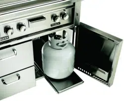
Cylinders must be stored
outdoors in a well-ventilat-
ed area out of the reach of
children. If the appliance
is stored indoors, the L.P.
cylinder must be removed
from the appliance, and
stored outside.
Turn o LP-gas supply at cylinder
when appliance is not in use.
Fermez l’alimentation en GPL à
la bouteille si l’appareil ne fonc-
tionne pas.
The LP-gas supply cylinder must
be disconnected when this ap-
pliance is not in use.
La bouteille de GPL doit être dé-
connectée si cet appareil ne fonc-
tionne pas.
Your local L.P. lling station
should be equipped with the
proper equipment to ll your
tank. If trading your tank in,
always ensure to obtain only
Type 1 20lb cylinders with an
overll protection device.
L.P. Connections
Connect the 3/8” are end of the
L.P. hose to the brass adapter on
the manifold (as shown in g-
ure 9-1). Connect the Regulator
to the tank (with the tank valve
fully closed). Although the ow
of gas is stopped when the Type
1 system is disconnected, you
should always turn the L.P. tank
main valve o after each use
and during transport of the tank
or unit. Insert the regulator inlet
into the tank valve and turn the
black coupler clockwise until the
coupler is tight. Do not over-
tighten the coupler.
To disconnect the coupler, rst
make sure the main tank valve
is turned o. Grasp the coupler
and turn counter clockwise. The
inlet will then disengage.
Gas Line Purging
To purge the L.P. gas line, make
sure all controls are in the OFF
position. Turn the main tank
valve on SLOWLY and turn one
burner control valve on the unit
to the “light” position (DO NOT
LITE GRILL). Leave control ON for
about 20 seconds to allow the
air in the system to purge. Wait
5 minutes before attempting to
light the burners.
Do not attempt lighting the grill
within 5 minutes after purging!
Figure 9-1
- Typical attachment to L.P. tank.
9

Precautions for Using Your Grill
10
READ THIS MANUAL CARE-
FULLY AND COMPLETELY
BEFORE USING YOUR GRILL
TO REDUCE THE RISK OF
FIRE, BURN HAZARD OR
OTHER INJURY.
Safety Precautions
1) NEVER LEAVE THE GRILL UN-
ATTENDED WHILE COOKING.
2) Avoid wearing loose-tting
garments or long sleeves while
using the grill. Never touch the
grill racks, hood or immediate
surrounding metal surfaces with
your bare hands as these areas
become extremely hot during
use and could cause burns.
3) Use an insulated glove or mitt
when opening and operating
the grill. Open grill lid slowly to
allow heat and smoke to escape
before fully opening.
4) Never lean over hot grill sur-
face or look directly into the grill
when attempting to light. The
grill hood must be fully opened
when lighting.
5) Do not heat unopened food
containers as pressure build-up
may cause container to burst.
6) Do not use aluminum foil to
line grill racks or drip pans. This
will alter combustion airow or
trap excessive heat in the control
area. This can result in melted
knobs and ignition modules.
These damages are specically
excluded from your warranty.
7) Never use charcoal in the grill.
8) Never operate the grill in a
windy area. If windy conditions
exist, install a suitable windbreak
(see page 2 for details).
9) Be aware that cooking exces-
sively fatty meats and other such
products will cause areups. In-
ternal res or damage caused by
are-ups or the grill being left
unattended while cooking, are
not the responsibility of LYNX
and any resulting damage is not
covered under the terms and
conditions of our warranty.
10) Never grill without the drip
pan in place. The drip pan must
be pushed all the way to the back
of the grill. Without the drip pan
in place, hot grease could leak
downward and produce a re or
explosion hazard.
11) Grease is extremely am-
mable. Let hot grease cool down
before attempting to handle
or dispose of it. The drip tray
should be cleaned of grease on
a regular basis.
12) Do not use the grill until a
leak check has been performed
(see page 11).
13) Do not operate grill under
the inuence of alcohol or drugs.
14) If equipped, never place
more than 30 pounds on a side
shelf. Do not lean on shelves.
15) If any burner does not light
or goes out during operation,
turn o all gas control knobs
with hood open and wait ve (5)
minutes before attempting to
re-light.
16) Prior to using grill ensure
that all tie down wires have been
removed from burners.
WA R N I N G
Spiders and insects can
nest in the burners of
this or any other grill,
and cause gas to ow
from the front of the
burner. This is a very
dangerous condition
which can cause a re to
occur behind the valve
panel, thereby damag-
ing the grill and making
it unsafe to operate.
If your grill has been
stored or unused for a
prolonged period, it is
recommended that the
burners be removed, in-
spected, and cleaned if
needed according to the
instructions on page 19.

11
Leak Testing
Figure 11-1
- Leak testing points when using natural gas.
Figure 11-2
- Leak testing points when using L.P. gas.
C A U T I O N D A N G E R
To prevent re or explosion hazard, DO NOT use or
permit sources of ignition in the area while perform-
ing a leak test. Perform leak test outdoors only. Never
perform a leak test with re or ame. DO NOT SMOKE
WHILE PERFORMING THE LEAK TEST!
To Perform Leak Test
1) Create a soapy solution of
equal parts mild dishwashing
detergent and water.
2) Conrm that all control knobs
are in the o position.
3) Turn on fuel supply. For natu-
ral gas, turn valve handle 1/4 turn
to align with gas ow. For L.P.,
turn cylinder valve knob counter
clockwise one full rotation.
4) Apply soap solution gener-
ously by paint brush or squirt
bottle on all connections and
ttings, as indicated in gures 1
and 2.
5) If “growing” bubbles appear
on any of the connection points,
then you have detected a gas
leak. IMMEDIATELY turn o the
gas supply by reversing step 3.
Fixing a Gas Leak
1) After shutting o gas sup-
ply, push in and turn on control
knobs to release pressure, then
turn the knobs back to o.
2) Wash o soapy solution with
cold water and towel dry.
3) Stop a leak by tightening
the loose joint, or by replacing
the faulty part with a replace-
ment part recommended by the
manufacturer. DO NOT attempt
to repair the L.P. cylinder valve if
it should become damaged; the
cylinder MUST BE REPLACED.
4) Perform a new leak test to en-
sure that no leaks are present.

Light
Switch
Rotis Grill Grill
(opt. ProSear)
30” Professional
Light
Switch
Rotis Grill Grill Grill
(opt. ProSear)
42” Professional
Light
Switch
Rotis Grill Grill Grill ProSear Rotis
54” Professional
Light
Switch
Rotis
(opt.)
Grill Grill
27” Professional
Light
Switch
Rotis Grill Grill Grill
(opt. ProSear)
36” Professional
Model Identification
12
Depending on the model, your Lynx grill may be equipped with up to three dierent burner types. The
operation of each burner type varies, so it is important to familiarize yourself with all three.
BURNER TYPE IDENTIFICATION
Brass
- This is the standard
main grill burner found under
the briquette trays
ProSear
- This is a high
intesnity infrared burner that
is optional on most models.
Rotis
- This is an infrared
burner found in the rear of
the grill above the grill racks.

13
Using the Grill
Grilling requires high heat for
searing and proper browning.
Most foods are cooked at the
“HI” heat setting for the entire
cooking time (with the lid open).
However, when grilling large
pieces of meat or poultry, it may
be necessary to turn the heat to
a lower setting after the initial
browning. This cooks the food
through without burning the
outside. Foods cooked for a long
time or foods basted with a sug-
ary marinade may need a lower
heat setting near the end of the
cooking time.
HOW TO SEAR
Searing locks in avor and juices
while allowing the outer surface
to absorb smoke and food aro-
ma that is produced as grease
and drippings are vaporized by
the burner. The result is a crisp,
avorful outside with a tender,
juicy inside. While the brass
burners in your grill are capable
of producing searing heat, the
ProSear infrared burner is specif-
ically designed for this purpose.
1) Properly pre-heat the grill by
following the lighting instruc-
tions on pages 14-15.
2) Leaving the burners set to “HI”,
place food on grill grids for 2-3
minutes per side, or until food is
easily turned without sticking.
3) Adjust the burners to a lower
setting and continue cooking un-
til desired doneness is reached,
turning the food as needed.
INDIRECT COOKING
Indirect cooking is achieved by
placing the food only on one side
of the grill. Leave the burner be-
low the food “OFF” and an adja-
cent grill burner on “HI”. Keep the
hood closed as much as possible
and regulate the heat with the
burner control, monitoring inter-
nal temperature with the hood
thermometer (if equipped).
1) Properly pre-heat the grill by
following the lighting instruc-
tions on pages 14-15.
2) Once grill has been preheated,
turn o any burners not required
for cooking. The lid should be
closed as much as possible while
using the indirect method.
3) Place the food on the grill and
cook to the desired doneness.
Adjust heat setting as required
to maintain desired temperature.
Before lighting the grill, perform the following checks to ensure safe operation:
o Specied clearances maintained to combustibles?
o All internal packaging removed?
o Knobs turn freely?
o Pressure regulator connected to proper gas type?
o Unit is leak tested and free of leaks?
o User informed of gas supply shut o valve location?
o Burners are sitting properly on orices?
o Wind is not blowing too strongly and/or hitting back of grill?
Once these checks are complete, you are ready to begin using your grill.
PRE-GRILLING CHECKLIST
WA R N I N G
Never place food over
a ProSear burner that
is not lit and pre-heat-
ed. Food particles and
grease dripping onto a
cold ProSear burner can
clog ports and damage
the ceramic burner. This
damage is not covered
by your warranty.

WA R N I N G
Never attempt to light
grill if odor of gas is pres-
ent. Hood must be open
when lighting. Keep face
and body as far from
grill as possible when
lighting. Always wait at
least 5 minutes before
attempting to relight a
hot burner.
Before proceeding, make sure
you have completed the check-
list on the previous page. These
checks should be performed be-
fore each use of the grill.
Follow these steps to light the
main brass grill burners:
1) Open hood completely. Do
not attempt to light grill with the
hood closed.
2) Check to ensure that all burner
control knobs are set to OFF.
3) Turn on main gas supply. Purge
if needed (see page 9).
4) Push in and turn burner con-
trol knob to LITE. Hold knob in for
5 seconds.
5) If burner does not light, turn
knob to OFF, wait 5 minutes to
allow gas to dissipate, and repeat
step 4 above.
PREHEATING THE GRILL
Before cooking, always preheat
the grill for best results. To pre-
heat the grill, light all main burn-
ers and set to HIGH. Close the grill
hood and allow to preheat for 10-
15 minutes, or until the tempera-
ture reaches 450°F.
After preheating, turn o all burn-
ers not required, carefully open
the hood, and adjust remaining
burners to desired cooking tem-
perature.
DO NOT LEAVE THE GRILL
UNATTENDED DURING THE
PREHEAT CYCLE OR AT ANY
TIME WHILE THE GRILL IS IN
USE. DO NOT ALLOW GRILL
TO PREHEAT FOR PRO-
LONGED PERIODS OF TIME.
OVERHEATING THE GRILL
CAN CAUSE DAMAGE TO
THE GRILL AND PERSONAL
PROPERTY.
MATCH LIGHTING
If burners will not light after sev-
eral attempts, the burners can be
match lit. If you’ve just attempt-
ed to light the burner with the
igniter, allow 5 minutes for any
accumulated gas to dissipate.
Make sure all knobs are in the
OFF position. Keep your face as
far away from the grill as possible.
With the hood open, pass the al-
ternate lighting rod with a lit pa-
per match installed to the ports
of the burner. Push and turn the
corresponding control knob of
the burner to LITE. If the burner
does not light in 4 seconds, turn
the knob o and wait 5 minutes
before attempting again (see g-
ure 14-1).
Figure 14-1
- Alternate
lighting rod.
LOW HEAT ADJUSTMENT
The valves on the grill feature
an adjustable low setting. Due
to uctuations in gas pressure,
heating value or gas conversion,
you may feel it necessary to ad-
just gas ow in the low position.
Do not adjust the infra-red rotis
or ProSear burners.
1) Light the burner.
2) Turn the control knob to the
lowest setting (all the way coun-
ter-clockwise).
3) Remove the knob.
4) While holding the valve shaft
with pliers, insert a thin at tipped
screwdriver into the shaft and
while viewing the burner, adjust
to a minimum stable ame (see
gure 14-2).
Figure 14-2
- Adjusting
brass burner low heat setting.
knob
removed
valve
stem
Lighting the Brass Burners
14

15
Using the ProSear Burner
The ProSear burner has some
special components and warn-
ings specic to its design. Be sure
to read this section completely
before using your ProSear.
SAFETY PRECAUTIONS
1) Do not light the grill until you
have carefully read and under-
stand the lighting instructions.
2) Ensure that burner ties and
packing materials are removed
before lighting the burners.
3) Special care should be ex-
ercised to avoid dropping any
liquids on the hot burners when
cleaning the cooking grids.
4) The cooking grids are heavy.
Extra caution must be used
when removing or replacing
the cooking grids. The tiles
within the IR burner(s) will be
permanently damaged if a cook-
ing grid or other object comes
into contact with them. Such
damage is not covered by the
product warranty and may cause
a re, burns or other injury.
WA R N I N G
Do not allow water to
spill on the IR burners.
Never allow water to
contact the hot burn-
ers. Never use water to
control are-ups. Water
contact will damage the
burners and is not cov-
ered by the warranty.
LIGHTING THE PROSEAR
1) Open hood completely. Do
not attempt to light grill with the
hood closed.
2) Check to ensure that all burn-
er control knobs are set to OFF.
3) Turn on main gas supply.
Purge if needed (see page 9).
4) Push in and turn burner con-
trol knob to LITE. Hold knob in
for 5 seconds.
5) If burner does not light, turn
knob to OFF, wait 5 minutes to
allow gas to dissipate, and re-
peat step 4 above.
The ProSear burner is ready to
use when it glows red, usually 2-
3 minutes after lighting.
PROSEAR IR SIDE BURNER
ONLY
For installation and hook-up, re-
fer to the manual supplied with
the unit. Follow these instruc-
tions for use.
Allow unit to cool completely
before grasping handle to lower
lid. Handle may be hot.
In windy conditions, remove the
lid from the unit by releasing
latch at rear and sliding out of
remaining hinge pin.
Keep lid closed when not in use.
BURNER CLEANING
After each use, it is impor-
tant to operate the ProSear
burners on “HI” with the
hood open to burn away
any food particles or drip-
pings. Operate the burners
on “HI” for 5 minutes.
Some ash may accumulate on
the burner surface over time.
Ocassionly, you should brush,
blow or vacuum this debris from
the surface of the burner. Only
perform this operation when the
burners are completely cool.
Every 3 to 6 months, inspect the
burner venturi (inlet) to ensure
there are no obstructions. If any
obstructions can be seen, then
follow the burner cleaning pro-
cedure on page 19.
COLD WEATHER
WA R N I N G
FOR L.P. UNITS
If lighting the main IR
burners in extremely
cold conditions, there
may be a possibility of
‘burn back’. Once lit,
if you hear a ‘whoosh-
ing’ sound, immediately
turn the burner knob o
to extinguish the ame.
Wait several minutes
before attempting to re-
light the burner.

The rotisserie system consists of
three main parts - the motor, the
skewer which holds the food,
and the infrared rotis burner. The
rotisserie evenly cooks large cuts
of meat by turning them contin-
uously in front of a high-intensi-
ty burner. The rotis is capable of
turning up to a 25 lb. cut of meat.
THE MOTOR
The rotisserie motor runs on 12
volt DC power that is supplied
by the grill. To power the motor,
plug the “L” shaped jack of the
power cord into the motor, and
plug the other end into the jack
provided on the left side of the
grill (see gure 16-1). This hook-
up allows for simple installation
and removal of the motor for
storage when not in use.
Figure 16-1
- Rotis motor
power jack located on grill
NOTE: The grill must be con-
nected to 115 volt AC power as
described on page 7 for the rotis
motor to function.
Install the motor onto the grill by
sliding it onto the bracket locat-
ed on the left side of the grill.
THE SKEWER
To load the skewer, slide one of
the meat holders onto the skew-
er. Push the skewer through the
center of the food, then slide the
second meat holder onto the
skewer. Center the food to be
cooked on the skewer then push
the meat holders rmly together.
Tighten the thumb screws (use
pliers if necessary). It may also be
necessary to wrap the food with
butchers string (never use nylon
or plastic string) to secure any
loose portions.
Remove the warming rack and,
if needed, remove the grill racks
and briquette trays to gain bet-
ter clearance. It is normal for the
skewer to ex when cooking
large foods. Place a basting pan
beneath the food for basting
and to ease cleaning.
Never operate a grill burner
with a basting pan in place.
The skewer for the rotis is assem-
bled into the motor assembly
by placing the pointed end into
the motor, and resting the short,
round end (threaded end on 27”
models) onto the support at the
opposite side of the grill. With
the skewer pushed into the mo-
tor, it should rest on the bracket.
The Lynx rotisserie features dual
positions to accomodate larger
cuts of meat or to allow slower
cooking (see gure 16-2). Any
food to be cooked should be a
minimum of 2” from the surface
of the infrared burner.
Figure 16-2
- Dual position
rotisserie system.
THE INFRARED BURNER
The location of the rotis burner
makes it more susceptible to
strong wind conditions (more
so than the main grill burners).
For this reason you should avoid
operating the rotis during windy
conditions. As an added safety
feature, the burner is equipped
with an automatic safety valve
which will not allow gas to ow
to the rotis burner if it is not
properly lit. To light the rotis
burner, follow this procedure:
1) Open hood completely. Do
not attempt to light grill with the
hood closed.
2) Load food onto skewer, and
install motor and skewer onto
grill in desired cooking position.
3) Check to ensure that all burn-
er control knobs are set to OFF.
4) Turn on main gas supply.
Purge if needed (see page 9).
5) Push in and turn burner con-
trol knob to LITE. Hold knob in
for 30 to 60 seconds.
continued...
Using the Rotisserie
16
Side view of grill
Rear position - for small
foods such as game hens
Front position - for
larger cuts of meat

17
Using the Smoker Box
By adding wood smoke to the
grilling process, meats and vege-
tables will have a more tradition-
al BBQ avor. In order to use the
smoker box, remove the rst set
of grill racks and set the smoker
box in the opening so that the
front and rear tabs rest on the
grill frame, and replace grill rack.
WA R N I N G
Never use smoker box
over a ProSear burner.
Wood Chips
There are many wood chips avail-
able and selection is based on
personal taste. The most com-
mon chips used are mesquite or
hickory. Always soak the chips in
water prior to putting them into
the box. Use the High position
to start the chips smoking, then
reduce the heat to a lower level
to prevent them from drying out
and aming. If the wood chips
do ame up, add a small amount
of water through the recessed
hole in the lid to extinguish the
ame. Use caution when adding
water to a hot box to avoid steam
burns. This tray may also be lled
with water to produce steam.
Whether smoking or steaming,
the grill should remain closed as
much as possible to maximize
the eect. During extended
roasting periods, it is normal to
add fresh wood chips and water
to the box several times. Limit
the amount of times the hood
is opened, as each opening can
add as much as 15 minutes to
the cooking time.
CAUTION: Handle the smoker
box with care. The cover be-
comes extremely hot when in
use. Use sturdy, properly insulat-
ed gloves or dry potholders.
It is recommended that a high
quality meat thermometer be
used when smoking, as cooking
times can vary greatly by cut of
meat or environmental factors.
Figure 17-2
- Smoker box
installed into grill for use.
6) If burner does not light, turn
knob to OFF, wait 5 minutes to
allow gas to dissipate, and re-
peat step 5 above.
Once lit, the rotis burner should
reach cooking temperatures in
about 1 minute. The glow will
even out in about 5 minutes.
If the burner will only stay lit with
the control knob depressed, the
thermocouple position may
need to be adjusted (see gure
17-1) to ensure proper function.
To adjust, ensure that only the
last 1/4 to 1/2” of thermocouple
extends over ceramic and that it
is located close to the surface.
Figure 17-1
- Proper rotis
thermocouple position.
NEVER ATTEMPT TO ADJUST
WHEN THE BURNER IS HOT.
MATCH LIGHTING
If the ignition system fails to light
the burner, it can be match lit ac-
cording to the procedure found
on page 14.
Always use basting pan
under the rotisserie to
keep drippings o the
burners and briquettes.
Never operate main grill
burners with basting
pan in place. Allow to
cool completely before
removing from grill.

The best way to keep your grill
looking great is to use a cover,
supplied by Lynx, when the grill
is not in use. While stainless steel
is very durable, some care is
required to ensure the long life
of your grill.
STAINLESS STEEL
Your grill has a directional pol-
ished grain - any cleaning should
be carried out along this grain
and not across it.
The grill is made from non-rust-
ing and non-magnetic stainless
steel. After initial usage, areas
of the grill may discolor from
the intense heat given off by the
burners - this is normal. There
are many different stainless steel
cleaners available. Always use
the mildest cleaning procedure
first, scrubbing in the direction
of the grain. To touch up notice-
able scratches in the stainless
steel, sand very lightly (at your
own risk) with dry 100 grit emery
paper in the direction of the
grain. Specks of grease can gath-
er on the surfaces of the stainless
steel and bake on to the surface
and give the appearance of rust.
To aid removal, use a fine to
medium grit non-metallic abra-
sive pad (Scotch Brite is good) in
conjunction with a stainless steel
cleaner. Always rub in the direc-
tion of the grain.
The best maintenance for stain-
less steel is to wipe it down with
a damp cloth. This is especially
true if a swimming pool is locat-
ed near the grill, as prolonged
contact with chlorinated water
can pit the stainless steel. This
damage is not covered by your
warranty. Never use steel “Brillo”
pads or similar products as these
will leave traces of material
behind which will quickly rust
and is not a defect in the Grill.
GRILL RACKS
The easiest way to clean the grill
racks is to do so immediately
after cooking and turning off
the burners. Wearing a long BBQ
mitt to protect your hand from
steam, dip a brass bristle brush
in hot water and scrub the grill
rack. Dip the brush frequently
as the steam aids the cleaning
process. If grill is allowed to cool
before cleaning, cleaning will be
more difficult.
NEVER USE WATER TO CLEAN THE
GRILL RACK ABOVE A PROSEAR
BURNER. LIQUID FALLING ONTO
AN UNLIT PROSEAR BURNER CAN
CAUSE PERMANENT DAMAGE.
THE GRILL RACK ABOVE THE
PROSEAR WILL NORMALLY BURN
CLEAN DURING THE 5 MINUTE
CLEANING BURN AFTER USE. IF
GRILL RACK REQUIRES FURTHER
CLEANING, ALLOW TO COOL
AND REMOVE FROM GRILL.
DRIP TRAY
The drip tray should be cleaned
after every use of the grill.
DO NOT ALLOW EXCESS GREASE
OR LIQUIDS TO ACCUMULATE
IN THE DRIP TRAY AS THIS MAY
CREATE A FIRE HAZARD.
Allow the grill to cool complete-
ly, then remove the drip tray by
pulling it out from the grill until
it stops, then lifting the front
edge until the drip tray comes
free. Clean with hot soapy water
or commercial cleaning product,
rinse, dry and reinstall in grill.
NEVER USE GRILL WITHOUT DRIP
TRAY PROPERLY INSTALLED.
BRIQUETTE TRAYS
Although they normally burn
clean with use, it may occassion-
ally be necessary to clean the bri-
quette trays. After allowing the
grill to cool completely, remove
the grill racks, then remove the
briquette trays by lifting the
front edge and pulling toward
you. Set the trays upside-down
onto their mounting points, and
operate the grill burners on high
for 20-30 minutes to burn the
briquettes clean. If it becomes
necessary to replace any or all
the briquettes, replacements
are available from your dealer.
Replace briquettes following the
instructions on page 6.
WA R N I N G
Always keep the area
surrounding the grill
free from all combus-
tible materials, liquids,
vapors, debris and ob-
structions. Maintain at
least 3” clearance around
grill for proper airow.
Cleaning the Grill
18

19
Burner Cleaning & Adjustment
Before removing burners
ensure the gas supply is o
and the knobs are in the
“o” position. Make sure
the grill has completely
cooled before proceeding.
To Remove Brass Burners:
Remove the grill racks and bri-
quette trays. Grasp the burner,
pull it up and slightly to the rear
of the unit so the burner head
comes o the brass orice at
the front. Angle the burner side-
ways, and remove. Be careful not
to upset the air shutter position.
Brass Burner Cleaning:
Clean the exterior of the burner
with a wire brush. Clear stub-
born scale with a metal scraper.
Clear any clogged ports with a
straightened paper clip. Never
use a wooden toothpick as it
may break o and clog the port.
Shake out any debris through
the air shutter. Use a ashlight
to inspect the burner inlet to en-
sure it is not blocked. If obstruc-
tions can be seen, use a metal
wire coat hanger that has been
straightened out to clean.
Brass Burner Air Adjustment
Each grill burner is tested and
adjusted at the factory prior to
shipment; however, variations
in the local gas supply or a con-
version from one gas to another
may make it necessary to adjust
the burners. The ames of the
Grill burners should be visu-
ally checked and compared to
g. 19-1. Flames should be blue
and stable with no yellow tips,
excessive noise or lifting. If any
of these conditions exist, check
if the air shutter or burner ports
are blocked by dirt, debris, or
spider webs. If needed, proceed
with air shutter adjustment.
Figure 19-1
- Showing
proper ame characteristics.
1½” flame
height
3
/
8
” flame
core
The amount of air which enters
a burner is governed by a sheet
metal disk at the inlet called an
air shutter. It is locked in place by
a set screw which must be loos-
ened prior to lighting the burner
for adjustment (see g. 19-2).
To Adjust:
1) Be extremely careful as the
burner may be very hot.
2) If the ame is yellow, indicat-
ing insucient air, turn the air
shutter counterclockwise to al-
low more air to the burner.
3) If the ame is noisy and tends
to lift away from the burner, indi-
cating too much air, turn the air
shutter clockwise.
4) Once adjusted, turn the burn-
er o and allow to cool. Remove
burner, tighten set screw and
reinstall the briquette trays and
grill racks.
Figure 19-2
- Air shutter set
screw location on burner
set screw
PROSEAR BURNER
For day-to-day cleaning, see in-
structions on page 15. If burner
inlet is obstructed, use a metal
wire coat hanger that has been
straightened out to clean.
WA R N I N G
IT IS CRITICAL TO CEN-
TER EVERY BURNER ON
ITS ORIFICE AND FOR
THE BURNERS TO REST
LEVEL AND NOT ROCK. IF
THE BURNERS ARE NOT
CENTERED CORRECTLY,
A VERY DANGEROUS
CONDITION EXISTS THAT
CAN CAUSE PERSONAL
INJURY AND DAMAGE
TO THE UNIT.

If the Grill does not function
properly, use this checklist before
contacting Lynx for service.
GRILL WON’T LIGHT
If the igniters are working cor-
rectly, next determine if gas is
reaching the burners. Ensure the
gas supply is turned on, and
that there are no leaks, accord-
ing to the procedure on page 11.
Attempt to match-light a burner
according to the procedure on
page 14. If the burner will light
with a match, then the igniter
may not be functioning cor-
rectly, or may not be adjusted
correctly. See above or call for
service. If the burner will not
match light, and the gas supply
has been confirmed, check the
burner for blockages according
to the procedure on page 19.
YELLOW FLAME/GAS SMELL
IF YOU SMELL GAS WHILE
THE GRILL IS OPERATING,
IMMEDIATELY TURN OFF ALL
BURNERS. Perform a leak test,
check for blockages and check
the air shutter adjustment
according to page 19.
NOTE: If the grill is operating in
a dusty area or if heavy grease
is present, some orange tips on
the burner flame are normal.
LOW/INSUFFICIENT HEAT
Ensure that adequate preheat
time has elapsed. Brass burners
should preheat for at least 15
minutes with the hood closed;
ProSear burners should preheat
for at least 3 minutes.
If adequate preheat time was
allowed, check the gas supply
for a damaged and/or kinked
supply line. Replace if necessary.
On LP units, a mostly empty tank
may not have sufficient pres-
sure to run the grill at high heat.
Replace with a full tank. Make
sure that the regulator/hose
assembly being used is the unit
supplied with the grill. On natu-
ral gas units, ensure that the
supply line is at least 3/4” diam-
eter. Check the gas supply pres-
sure to ensure at least 7” W.C.
(0.25 psi) for natural gas, 11” W.C.
(0.4 psi) for LP.
If gas supply is adequate, check
burners for blockages and check
flame characteristics according
to the procedure on page 19
and clean or adjust air shutter if
needed. Check also that there is
no pressure being applied to the
regulator attached to the back
of the grill. This regulator con-
tains a flexible diaphragm and
should not be allowed to touch
the grill body or surroundings.
Check to make sure that the
burners and the drip tray are
clean and free from obstruc-
tions. Clean if necessary. NOTE:
No part of the grill should ever
be lined with aluminum foil as
it will interfere with airflow and
can cause a low heat condition.
BURNER BLOWS OUT
First determine if the problem
is being caused by location.
If location is subject to high
winds, reposition grill to provide
some protection. Check the gas
supply and flame characteris-
tic according to the procedure
under Low/Insufficient Heat.
Check to ensure that the burners
are correctly positioned in the
grill according to the procedure
on page 19. Correctly installed
burners should be seated firmly
with no side-to-side movement.
ROTISSERIE WON’T LIGHT
Follow the same procedure as
described above for the grill
burners to diagnose problems
with the Rotisserie IR burner. The
IR burner flame may be hard to
see in bright sunny conditions.
LIGHTS WON’T OPERATE
Ensure that the grill has AC
power by removing the D cell
battery according to the instruc-
tions on page 7, and then press-
ing a burner control knob to test
the spark igniter. If the ignit-
ers don’t function, no AC power
is connected. If the igniters do
function, replace the bulb.
Troubleshooting
20

21
Light Bulb Replacement
Replacing the Briquettes
TO REPLACE BRIQUETTES
The special Lynx ceramic bri-
quettes are secured to the trays
with stainless steel clips. To in-
sert a briquette into the tray, it
is necessary to remove the clip
from one side of the empty slot.
This is done by bending the re-
taining tabs for the clip located
on the back side of the briquette
tray as shown below.
WA R N I N G
The edges of the clips
may be sharp. Pliers
MUST be used to remove
clips - never attempt to
remove them by hand as
injury may result.
Figure 21-1
- Remove glass cover to access work light bulb.
TO CHANGE LIGHT BULBS
Remove the glass light cover by
grasping the edge of the glass
and gently prying it o. It may
be necessary to remove one
screw. Pull the old bulb straight
out from socket - do not twist.
Replacement bulbs are halogen,
12 volt, T3 type with a G4 bipin
base. The 54” grill uses two 5W
bulbs, all others use one 10W.
AVOID TOUCHING THE
GLASS OF NEW BULBS.
Install new bulb by gently press-
ing it into the socket. Replace
glass cover by gently snapping
back into place.

Side Burner/LPSGE Gas Hookup
22
BUILT-IN INSTALLATION
1) Shut o gas supply at main
valve.
2) Disconnect all plumbing (if al-
ready attached) from grill and
gas supply valve.
3) Remove all ttings from grill
manifold.
4) Install side burner into cutout
in countertop.
5) Connect gas supply to grill
and side burner as shown in
the gure at right for your
proper gas type.
6) Turn gas supply on and leak
test all connections.
CART INSTALLATION
1) Shut o gas supply at main
valve.
2) Disconnect all plumbing (if al-
ready attached) from grill and
gas supply valve.
3) Remove all ttings from grill
manifold.
4) Install side burner onto cart
according to the directions
supplied with the cart mount-
ing kit.
5) Connect gas supply to grill
and side burner as shown in
the gure at right for your
proper gas type.
6) Turn gas supply on and leak
test all connections.
Natural Gas
LP Gas

23
Lighting the Side Burner or LPSGE
WA R N I N G
Never attempt to light
burner if odor of gas
is present. Lid must be
open/o when lighting.
Keep face and body as
far from unit as possible
when lighting. Always
wait at least 5 minutes
before attempting to re-
light a hot burner.
Before proceeding, make sure
you have completed a leak test.
This check should be performed
before each use of the side burn-
er or grill extender.
Follow these steps to light the
burners:
1) Open or remove lid complete-
ly. Do not attempt to light burn-
ers with the lid closed.
2) Check to ensure that all burn-
er control knobs are set to OFF.
Test ignition system by pressing
control knob in and listening
for clicking sound of igniter. If
no sound occurs, proceed with
troubleshooting or match-light
the burner.
3) Turn on main gas supply.
Purge if needed (see page 9).
4) Push in and turn burner con-
trol knob to LITE. Hold knob in
for 5 seconds.
5) If burner does not light, turn
knob to OFF, wait 5 minutes to
allow gas to dissipate, and re-
peat step 4 above.
PREHEATING THE LPSGE
Before cooking, always preheat
the ProSear burner for best re-
sults. To preheat, light the burn-
er, set to HIGH and allow to pre-
heat until the burner glows red,
usually about 2-3 minutes.
DO NOT LEAVE THE UNIT
UNATTENDED DURING
THE PREHEAT CYCLE OR AT
ANY TIME WHILE IN USE.
DO NOT ALLOW UNIT TO
PREHEAT FOR PROLONGED
PERIODS OF TIME. OVER-
HEATING THE UNIT CAN
CAUSE DAMAGE TO THE
UNIT AND TO PERSONAL
PROPERTY.
MATCH LIGHTING
If burners will not light after sev-
eral attempts, the burners can be
match lit. If you’ve just attempt-
ed to light the burner with the
igniter, allow 5 minutes for any
accumulated gas to dissipate.
Make sure all knobs are in the
OFF position. Keep your face as
far away from the unit as pos-
sible. With the lid removed, pass
the alternate lighting rod with a
lit paper match installed to the
ports of the burner. Push and
turn the corresponding control
knob of the burner to LITE. If the
burner does not light in 4 sec-
onds, turn the knob o and wait
5 minutes before attempting
again.
LOW HEAT ADJUSTMENT
NOTE: ADJUSTMENT IS
FOR SIDE BURNERS ONLY.
PROSEAR BURNERS ARE
PRESET AT THE FACTORY
AND SHOULD NOT BE AD-
JUSTED.
The valves on the side burner
feature an adjustable low set-
ting. Due to uctuations in gas
pressure, heating value or gas
conversion, you may feel it nec-
essary to adjust gas ow in the
low position.
1) Light the burner.
2) Turn the control knob to the
lowest setting (all the way coun-
ter-clockwise).
3) Remove the knob.
4) While holding the valve shaft
with pliers, insert a thin at
tipped screwdriver into the shaft
and while viewing the burner,
adjust to a minimum stable
ame (see gure 23-1).
Figure 23-1
- Adjusting
side burner low heat setting.
knob
removed
valve
stem

I. Limited Lifetime Warranty. The stainless steel body housings, the solid brass grill burners and the
ProSear burners* are warranted to be free from defects in material and workmanship when subjected to
normal domestic use and service for the lifetime of the original purchaser. This warranty excludes surface
corrosion, scratches, and discoloration which may occur during regular use. This warranty is limited to the
replacement of the defective parts. *Does not include the rotisserie infra-red burner.
II. Limited Five-Year Warranty. The structural integrity of the interior grill parts, exterior, and drip pans
are warranted to be free from defects in material and workmanship, when subjected to normal domes-
tic use and service, for a period of five years from the date of purchase. This warranty is limited to the
replacement of the defective parts.
III. Limited One-Year Warranty. All other grill components are warranted to be free from defects in
material and workmanship for a period of one year from the original date of purchase. Lynx will replace
or repair parts found to be defective at no cost to the original purchaser.
IV. Limitations & Exclusions
1) Warranty applies only to the original purchaser and may not be transferred.
2) Warranty is in lieu of all other warranties, expressed or implied and all other obligations or liabilities
related to the sale or use of its grill products.
3) Warranty shall not apply and Lynx is not responsible for damage resulting from misuse, abuse, altera-
tion of or tampering with the appliance, accident, hostile environment, flare-up fires, improper installa-
tion, or installation not in accordance with the instructions contained in this manual, or the local codes.
4) Lynx shall not be liable for incidental, consequential, special or contingent damages resulting from
its breach of this written warranty or any implied warranty.
5) Some states do not allow limitations on how long an implied warranty lasts, or the exclusions of or
limitations on consequential damages. This warranty gives you specific legal rights and you may have
other rights which vary from state to state.
6) No one has the authority to add to or vary Lynx’s warranty, or to create for Lynx any other obliga-
tion or liability in connection with the sale or use of its products.
V. What is not covered. Lynx shall not be responsible for and shall not pay for the following:
1) Installation or start-up, damages or problems caused by improper installation or use;
2) Service by an unauthorized service provider;
3) Damage or repair due to service by an unauthorized service provider or use of unauthorized parts;
4) Units installed in non-residential applications such as day-care centers, bed and breakfast centers,
churches, nursing homes, restaurants, hotels, schools, etc.;
5) To correct normal adjustments or settings, due to improper installation, commissioning or local gas
supply properties;
6) Shipping and handling costs, export duties, installation, removal, or re-installation cost;
7) The cost of a service call to diagnose trouble.
See previous page for information on how to obtain warranty service.
Warranty
24

25
How to Obtain Service
Before you call for service:
1) Is there Gas Supplied to the Grill?
2) Is there a power outage in the area (lights will not work)?
3) Have you recently refilled the LP Tank?
Before calling for service, please make sure you have the following information:
1) Model number
2) Date of purchase
3) Proof of purchase by the original owner
4) Serial number. The serial number can be located on the rating plate, which is located either under the
drip tray, on the heat shield behind the front panel, or on the inside left cabinet wall (for most free-
standing grills).
For warranty service, contact the LYNX Customer Service Department for an authorized service agent
near you. Our number is (888) Buy-Lynx (888-289-5969). Provide the Model Number, Serial Number, date
of installation, and a brief description of the problem.
Your satisfaction is of the utmost importance to us. If a problem cannot be resolved to your satisfaction,
please write, fax or email us:
Lynx Professional Grills
6023-25 Bandini Blvd., Commerce, CA 90040
Service: (888) Buy-Lynx (888-289-5969)
Tel: (323) 838-1770
Fax: (323) 838-1778
www.lynxgrills.com
Contact Lynx as well for replacement parts. Parts are shipped F.O.B. Commerce, CA.
IF SHIPMENT ARRIVED DAMAGED:
1) VISIBLE LOSS OR DAMAGE: Be certain this is noted on freight bill or express receipt and signed by
person making delivery.
2) FILE CLAIM FOR DAMAGES IMMEDIATELY, regardless of extent of damage.
3) CONCEALED LOSS OR DAMAGE: If damage is unnoticed until merchandise is unpacked, notify trans-
portation company or carrier immediately and file “concealed damage” claim with them. This should
be done within (15) days of date delivery is made to you. Be sure to retain container for inspection.
We cannot assume responsibility for damage or loss incurred in transit.

Wiring Diagrams
3
CONNECTORS
TO ROTIS
DOME LIGHT
INSIDE GRILL
SIDE BURNER CONNECTOR
FOR LED’S
TRANSFORMER POWER
IN FOR LIGHTS
TRANSFORMER POWER IN FOR
IGNITION AND ROTIS
LED (-)
LED (+)
Dome Light
Inside Grill
Transformer
Power in for
Lights
Side Burner Connector
for LED’S
Transformer Power in for
Ignition and Rotis
To Rotis
Connectors
.250 x .032
Terminal
.187 x .032
Terminal
Battery Holder
1821 – 25
Light Switch
LED (-)
LED (+)
Pink
Connectors
Converter/
Backup
Module
.110 x .031
Terminals
Resistor
LED’S
Halogen Light Inside Grill
Ignition Switches
Key for 27” Grill
Igniter
To
Rotis
Light Switch
Power
In
Orange Wires to Igniters
Red Wires
Black Wires
Insulated Wire to Lamp
Diode
Pink
Connector
Blue
Connector
Key for 30”, 36”, 42”, and 54” Grills
Orange Wires to Igniters
Red Wires
Black Wires
Insulated Wire to Lamp
26


Questions? Talk to your Lynx Authorized Dealer or visit our website at www.lynxgrills.com
Lynx Professional Grills • 6023 E. Bandini Blvd. • Commerce, CA 90040 • (888) 879-2322
Lynx began as the vision of a group of people with
over a century of collective experience, who for 35
years were manufacturing top-of-the-line stainless
steel products for the commercial food service industry.
Lynx has taken that same quality, workmanship,
service and innovation and incorporated it into the
Lynx Professional Grills line of products. The combi-
nation of the best materials, fine craftsmanship and
original ideas is why Lynx products are in a class of
their own.
These original commercial products are found in
restaurants, hotels and theme parks across the USA:
• TGI Fridays • Applebee's • Houston's • Red Lobster
• Hard Rock Café • Wolfgang Puck's • Cheesecake
Factory • Red Robin • Planet Hollywood • Hilton •
Hyatt • Four Seasons Marriott Le Meridian • Sheraton
• Conrad International Bellagio • New York New
York • MGM Grand • Treasure Island • Mirage • Paris
• Venetian • Excalibur • Manadalay Bay • Riviera
• Desert Inn • Hard Rock Hotel • Disney World
The Lynx Story…
*,"--" Ê,-
