Loading ...
Loading ...
! Never wire the speaker negative cable directly
to ground.
! Never band together multiple speaker’s nega-
tive cables.
! If the system remote control wire of the ampli-
fier is connected to the power terminal via the
ignition switch (12 V DC), the amplifier will re-
main on with the ignition whether the car
stereo is on or off, which may exhaust battery
if the engine is at rest or idling.
! Install and route the separately sold battery
wire as far as possible from the speaker wires.
Install and route the separately sold battery
wire, ground wire, speaker wires and the am-
plifier as far away as possible from the anten-
na, antenna cable and tuner.
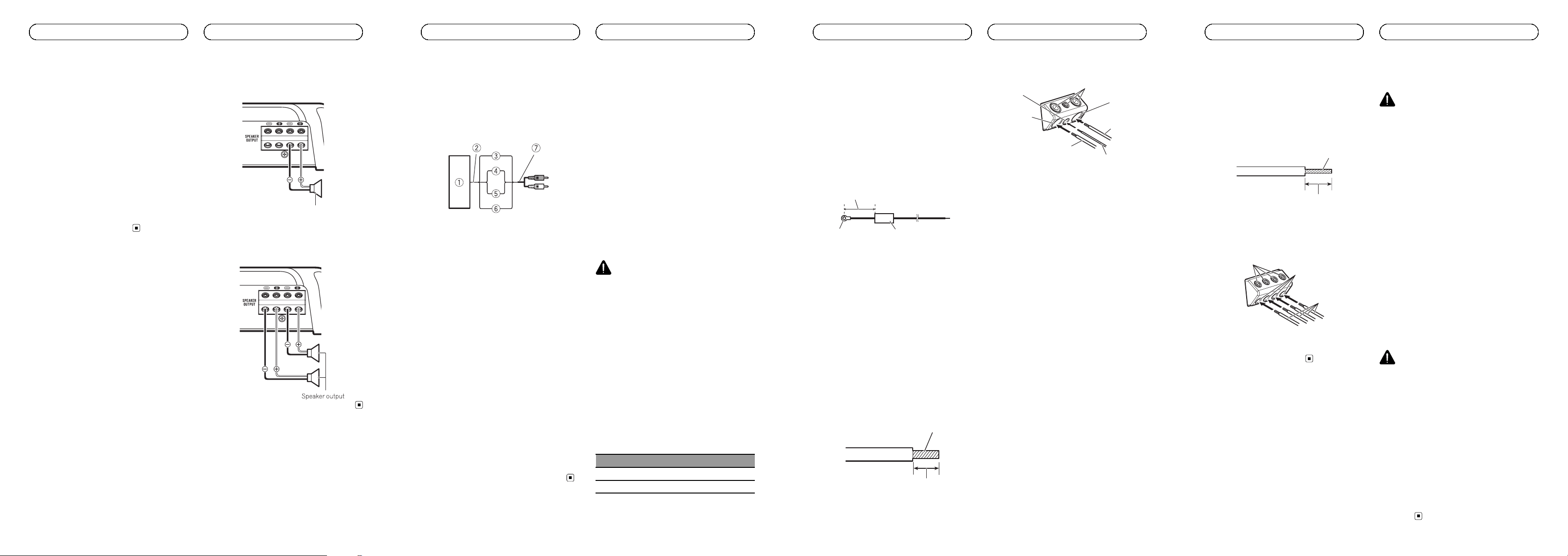
Connecting the speakers
This amplifier can be connected to two speak-
ers in parallel. Connect the speaker leads to
suit the mode according to the figure shown
below.
Precautions for parallel connection
! When wiring two speakers in parallel, make
sure that the synthetic impedance is from
1 W to 8 W to prevent the amplifier from
catching fire, generating smoke and/or
being damaged.
! When connected in parallel with the syn-
thetic impedance less than 1 W, as a nor-
mal function, this amplifier may
automatically be set on mute if outputting
high volume sound. Turn down the volume
until the mute function is canceled.
When connecting to one speaker
Speaker output
When connecting to two speakers
The output from two speakers is the same as
that of one speaker.
Speaker output
<5707000012760V>9
En
Connecting the units
Connections when using
the speaker input wire
Connect the car stereo speaker output wires
to the amplifier using the supplied speaker
input wire with RCA pin cord.
1 Car Stereo
2 Speaker output
3 Red: Right +
4 Black: Right *
5 Black: Left *
6 White: Left +
7 Speaker input wire with RCA pin cord
To the RCA input jack of this unit
Notes
! If speaker input wires from a headunit are
connected to this amplifier, the amplifier will
automatically turn on when the headunit is
turned on. When the headunit is turned off,
the amplifier turns off automatically. This
function may not work with some headunits.
In such cases, please use a system remote
control wire (sold separately). If multiple am-
plifiers are to be connected together synchro-
nously, connect the head unit and all
amplifiers via the system remote control wire.
! Connect the system remote control wire when
you wish to only turn on the car stereo, not the
amplifier.
! This amplifier automatically selects an input
signal mode between the RCA level and the
speaker level by detecting an input signal.
Solderless terminal
connections
! Since the wire will become loose over time,
it must be periodically inspected and tigh-
tened as necessary.
! Do not solder or bind the ends of the
twisted wires.
! Fasten while making sure to not to clamp
the insulating sheath of the wire.
! Use the supplied hexagonal wrench to
tighten and loosen the terminal screw of
the amplifier and use it to securely fasten
the wire. Be careful to avoid excessive tigh-
tening of this screw, which may damage
the wire.
Connecting the power terminal
WARNING
If the battery wire is not securely fixed to the term-
inal using the terminal screws, there is a risk of
overheating, malfunction and injury, including
minor burns.
! Always use the recommended battery and
ground wire, which is sold separately. Con-
nect the battery wire directly to the car bat-
tery positive (+) terminal and the ground
wire to the car body.
! Recommended wires size (AWG: American
Wire Gauge) is as follows. The battery wire,
the ground wire and the optional direct
ground wire must be same size.
! Use a wire of 8 AWG to 16 AWG wire for the
speaker wire.
Battery wire and ground wire size
Wire length Wire size
less than 3.6 m (11 ft. 10 in.) 6 AWG
less than 6.4 m (20 ft. 12 in.) 4 AWG
<5707000012760V>10
En
Connecting the units
1 Route battery wire from engine com-
partment to the vehicle interior.
! When drilling a cable pass-hole into the ve-
hicle body and routing a battery wire thor-
ough it, take care not to short-circuit the
wire damaging it by the cut edges or burrs
of the hole.
After completing all other amplifier connec-
tions, finally connect the battery wire terminal
of the amplifier to the positive + battery term-
inal.
2
1
3
1 Positive + terminal
2 Battery wire (sold separately)
The maximum length of the wire between
the fuse and the positive + terminal of the
battery is 30 cm (12 in.).
3 Fuse 100 A (GM-D8701 and GM-DX871) /
150 A (GM-D9701 and GM-DX971) (sold se-
parately)
Each amplifier must be separately fused at
100 A (GM-D8701 and GM-DX871) / 150 A
(GM-D9701 and GM-DX971).
2 Use wire cutters or a utility knife to
strip the end of the battery wire, ground
wire and system remote control wire to ex-
pose about 10 mm (3/8 in.) of the end of
each of the wires, and then twist the ex-
posed ends of the wires.
Twist
10 mm (3/8 in.)
3 Connect the wires to the terminal.
Fix the wires securely with the terminal
screws.
3
6
1
5
4
2
7
1 Battery wire
2 Power terminal
3 Ground wire
4 GND terminal
5 System remote control wire
6 System remote control terminal
7 Terminal screws
<5707000012760V>11
En
Connecting the units
Connecting the speaker output
terminals
1 Use wire cutters or a utility knife to
strip the end of the speaker wires to ex-
pose about 10 mm (3/8 in.) of wire and
then twist the wire.
Twist
10 mm (3/8 in.)
2 Connect the speaker wires to the
speaker output terminals.
Fix the wires securely with the terminal
screws.
1
3
2
1 Terminal screws
2 Speaker wires
3 Speaker output terminals
Before installing the amplifier
WARNING
! To ensure proper installation, use the supplied
parts in the manner specified. If any parts
other than those supplied are used, they may
damage internal parts of the amplifier, or be-
come loose causing the amplifier to shut
down.
! Do not install in:
— Places where it could injure the driver or
passengers if the vehicle stops suddenly.
— Places where it may interfere with the dri-
ver, such as on the floor in front of the dri-
ver’s seat.
! Install tapping screws in such a way that the
screw tip does not touch any wire. This is im-
portant to prevent wires from being cut by vi-
bration of the car, which can result in fire.
! Make sure that wires do not get caught in the
sliding mechanism of the seats or touch the
legs of a person in the vehicle as short-circuit
may result.
! When drilling to install the amplifier, always
confirm no parts are behind the panel and
protect all cables and important equipment
(e.g. fuel/brake lines, wiring) from damage.
CAUTION
! To ensure proper heat dissipation of the ampli-
fier, ensure the following during installation:
— Allow adequate space above the amplifier
for proper ventilation.
— Do not cover the amplifier with a floor mat
or carpet.
! Place all cables away from hot places, such
as near the heater outlet.
! The optimal installation location differs de-
pending on the car model. Secure the ampli-
fier at a sufficiently rigid location.
! Check all connections and systems before
final installation.
! After installing the amplifier, confirm that the
spare tire, jack and tools can be easily re-
moved.
<5707000012760V>12
En
Connecting the units Installation
Loading ...
Loading ...
Loading ...