Loading ...
Loading ...
Loading ...
4
-,,
-.-
ADJUSTMENTSANDAUXILIARYCONTROLS AVAILABLEWITH
THE ROOM CABINET ANDCONTROLBOXFRONTPLATEREMOVED
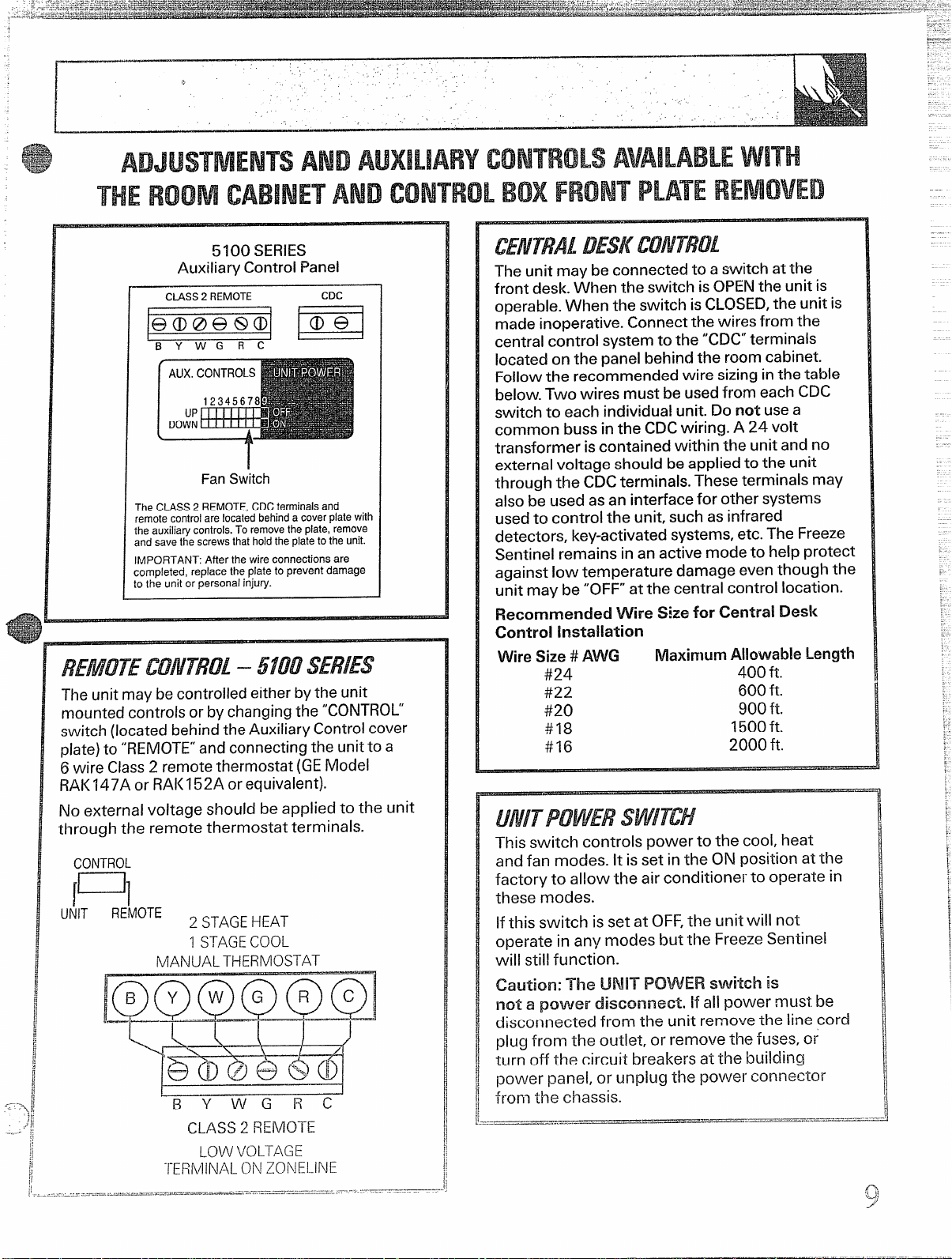
5100 SERiES
AuxiliaryControlPanel
CLASS2REMOTE
CDC
.@@@e@@
p]
BY WGRC
Fan Switch
TheCLASS2 REMOTE,CDCterminalsand
remotecontrolarelocatedbehindacoverplatewith
the auxiliatycontrols.Toremovethe plate,remove
andsavethe screwsthatholdthe platetothe unit.
IMPORTANT After the wire connections are
completed, replace the plate to prevent damage
tothe unit or personal injury.
REMOTECONTROL– 5100SERIES
Theunitmaybe controlledeitherbythe unit
mountedcontrolsorbychangingthe “CONTROL
switch(locatedbehindtheAuxiliaryControlcover
plate) to “REMOTE”and connecting the unit to a
6 wire Class2 remotethermostat(GEModel
RAK147AorRAI<I52A orequivalent).
No external voltage should be applied to the unit
throughthe remote thermostat terminals.
CONTROL
[u]
UfilT
REMOTE
2 STAGEHEAT
1 STAGE COOL
MANUAL THERMOSTAT
-aa
I
-1”= “ 1
~
J
BY WGRC
CLASS 2 REMOTE
LOWVOLTAGE
TERMINALONZONEI.INE
.,....,’.=
- ..——
---.-....—
.....—-.———!-=r—-.--=-—...=.--—-----
— .—..... .“,.,-,
The unitmay be connectedto a switchatthe
frontdesk.When the switchisOPENthe unitis
operable.When the switchisCLOSED,the unitis
made inoperative.Connectthe wiresfromthe
centralcontrolsystemto the “CDC”terminals
locatedon the panelbehindthe roomcabinet.
Followthe recommendedwire sizinginthe table
below.Two wires mustbe usedfrom each CDC
switchto each individualunit.Do not usea
common bussinthe CDCwiring. A 24 volt
transformeriscontainedwithin the unitand no
externalvoltageshouldbe appliedto the unit
throughthe CDCterminals.Theseterminalsmay
alsobe usedasan interfaceforothersystems
usedto controlthe unit,suchasinfrared
detectors,key-activatedsystems,etc.The Freeze
Sentinelremains inan activemodeto helpprotect
againstlow temperature damage eventhoughthe
unitmay be “OFF”at the centralcontrollocation.
Recommended
Wire Sizefor Central Desl(
Control installation
WireSize# AWG
MaximumAl!owabieLength
#24
400 ft.
#22
600 ft.
#20
900 ft.
#18
1500ft.
#16
2000 ft.
Thisswitch controlspower to the cool,heat
andfan modes. It isset inthe ON positionat the
factoryto allow the air conditionerto operate in
these modes.
Ifthisswitch isset at OFF,the unitwill not
operate in any modes butthe FreezeSentinel
will stillfunction.
Caution: The UNITPOWERswitch is
not a povverdisconnect,
ifall power must be
disconnected from the unit remove the line cord
plugfrom the outlet, or remove the fuses,or
turn off the circuit breakersat the bui!ding
power panel, or unplug the power connector
from the chassis.
Loading ...
Loading ...
Loading ...