FORM NO. Z2517
REV. D-10/03/2018
PERLICK RESIDENTIAL UNDERCOUNTER ICE MAKERS
To prevent appliance damage and injury, read these instrucons
thoroughly prior to installaon.
H50IMS/-AD
PRODUCT MANUAL
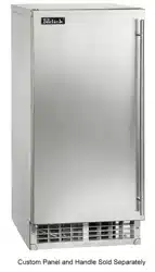
H50IMS
H50IMS-AD
15” SIGNATURE SERIES CLEAR ICE MAKER
15” ADA COMPLIANT CLEAR ICE MAKER

2 | perlick.com/residential
PERLICK RESIDENTIAL ICE MAKER MANUAL
TABLE OF CONTENTS
INTRODUCTION
Congratulaons on your purchase of a Perlick Residenal
undercounter appliance. This manual has been prepared to
assist you in the installaon of your undercounter ice maker.
We dedicate considerable me to ensure that our products
provide the highest level of customer sasfacon. We thank
you for selecng Perlick products for your home and assure you
of our connuing interest in your sasfacon.
CONTENTS
3 Safety Consideraons
4 Construcon
5 Electrical / Refrigerant
6 Niche / Product Dimensions / Connecons
10 Prior To Installaon
11 Installaon Instrucons
18 Setup
18 Electrical Connecon
19 Water Supply And Drain Connecons
20 Final Checklist
20 Startup
21 Maintenance
26 Preparing The Appliance For Periods Of Non-Use
27 Warranty Informaon

perlick customer service (800)558-5592 | 3
PERLICK RESIDENTIAL ICE MAKER MANUAL
SAFETY CONSIDERATIONS
DANGER
!
IMPORTANT SAFETY INFORMATION
This manual should be read carefully before the ice maker
is installed and operated. Only qualied service technicians
should install, service, and maintain the ice maker. Read the
warnings contained in this booklet carefully as they give
important informaon regarding safety. Please retain this
booklet for any further reference that may be necessary.
DAN This indicates that a hazardous situaon
may occur when instrucons are not followed. It is
imperave that direcons in this guide are followed to
prevent possible serious injury or death.
This indicates a situaon where minor
injury, product or cabinet damage may occur if the following
instrucons are not followed.
This highlights informaon that is of
signicant importance.
WARNING
DANGER
!
CAUTION
This ice maker should be desned only to
the use for which it has been expressly conceived. Any other
use should be considered improper and therefore dangerous.
The manufacturer cannot be held responsible for eventual
damage caused by improper, incorrect, and unreasonable
use. To reduce the risk of death, electric shock, serious injury,
or re, follow basic precauons including the following:
▪ This unit requires an independent power supply. See the
nameplate for proper voltage and breaker/fuse size. Failure
to use a proper breaker or fuse can result in a tripped
breaker, blown fuse, or damage to exisng wiring. This
could lead to heat generaon or re.
▪ THIS APPLIANCE MUST BE GROUNDED: This unit is
equipped with a 3-prong grounding plug to reduce the
risk of potenal shock hazards. It must be plugged into a
properly grounded, independent wall outlet. If the outlet is
a 2-prong outlet, it is your personal responsibility to have
a qualied electrician replace it with a properly grounded,
independent 3-prong wall outlet. Do not remove the
ground prong from the power cord and do not use an
adapter plug.
▪ Do not use an extension cord.
▪ Make sure the control switch is in the “OFF” posion
before plugging in or unplugging the unit to reduce the risk
of electric shock.
▪ Do not use a unit with a damaged power cord. The power
cord should not be altered, jerked, bundled, weighed
down, pinched, or tangled. Such acons could result in
electric shock or re. To unplug the unit, be sure to pull the
plug, not the cord, and do not jerk the cord.
▪ To reduce the risk of electric shock, do not touch the plug
or control switch with damp hands.
▪ This unit should be disassembled or repaired only by
qualied service personnel to reduce the risk of electric
shock, injury, or re.
▪ Do not make any alteraons to the unit. Alteraons could
result in electric shock, injury, re, or damage to the unit.
4 | perlick.com/residential
PERLICK RESIDENTIAL ICE MAKER MANUAL
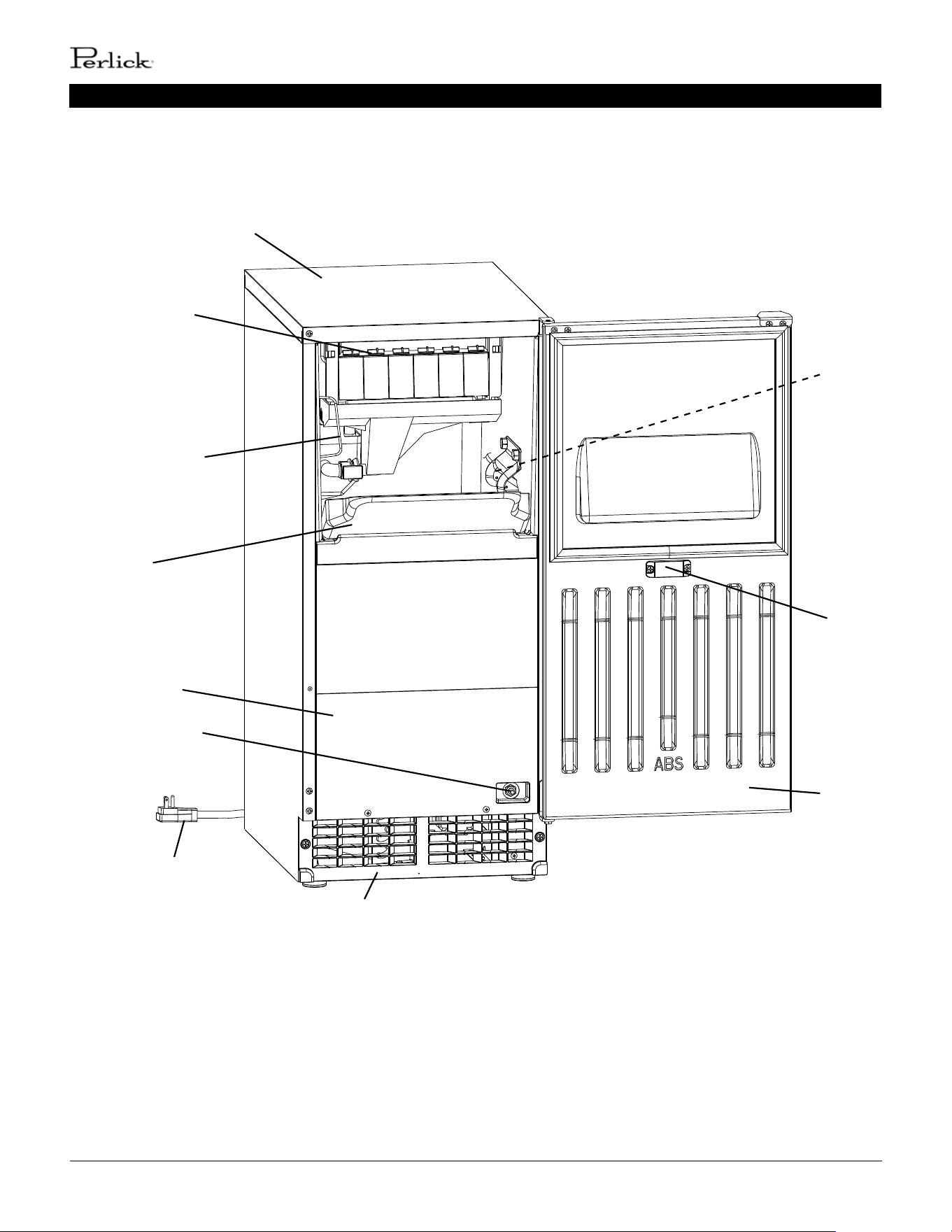
CONSTRUCTION
Top Panel
Ice Making
Mechanism
Scoop Holder
Slope
Front Panel
Control Switch
Power Cord
Louver
Magnet
Catch
Door
Bin Control
Thermostat
Bulb

perlick customer service (800)558-5592 | 5
PERLICK RESIDENTIAL ICE MAKER MANUAL
ELECTRICAL / REFRIGERANT
The nameplate provides electrical and refrigerant data. The
nameplate is located inside the storage bin. For cercaon
marks, see the nameplate.
We reserve the right to make changes in specicaons and
design without prior noce.
Model Number H50IMS-R
Electrical Supply 115-120V, 60 Hz., Phase 1
Service 3.4 amp circuit
Power/Cord Type/ Length NEMA 5-15P w/6’ power cord
Design Pressure HI-240PSI LO-120PSI
Refrigerant 134a 4.2 OZ.
6 | perlick.com/residential
PERLICK RESIDENTIAL ICE MAKER MANUAL
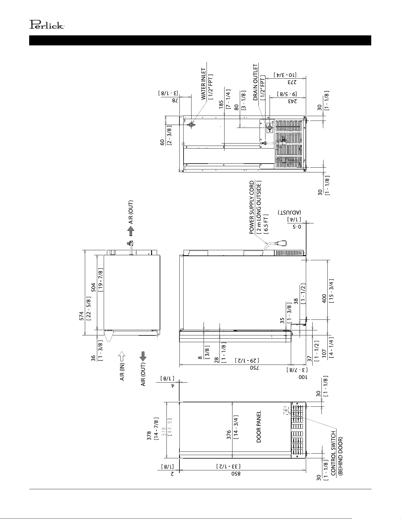
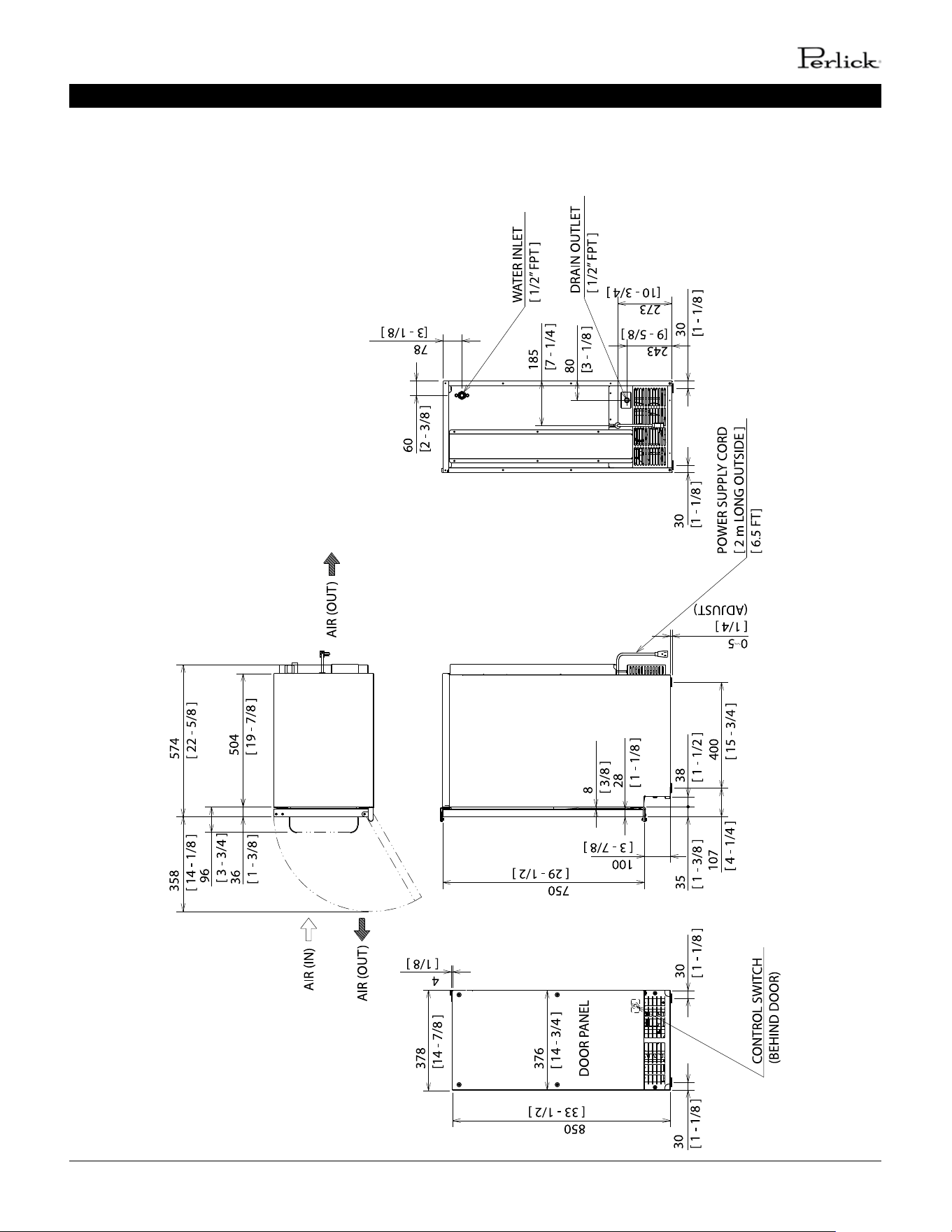
NICHE / PRODUCT DIMENSIONS / CONNECTIONS
perlick customer service (800)558-5592 | 7
PERLICK RESIDENTIAL ICE MAKER MANUAL
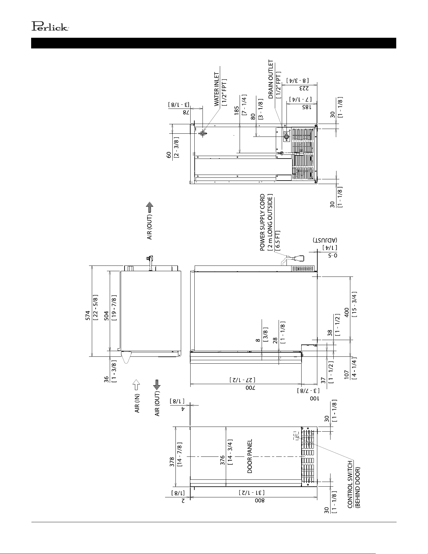
NICHE / PRODUCT DIMENSIONS / CONNECTIONS
8 | perlick.com/residential
PERLICK RESIDENTIAL ICE MAKER MANUAL
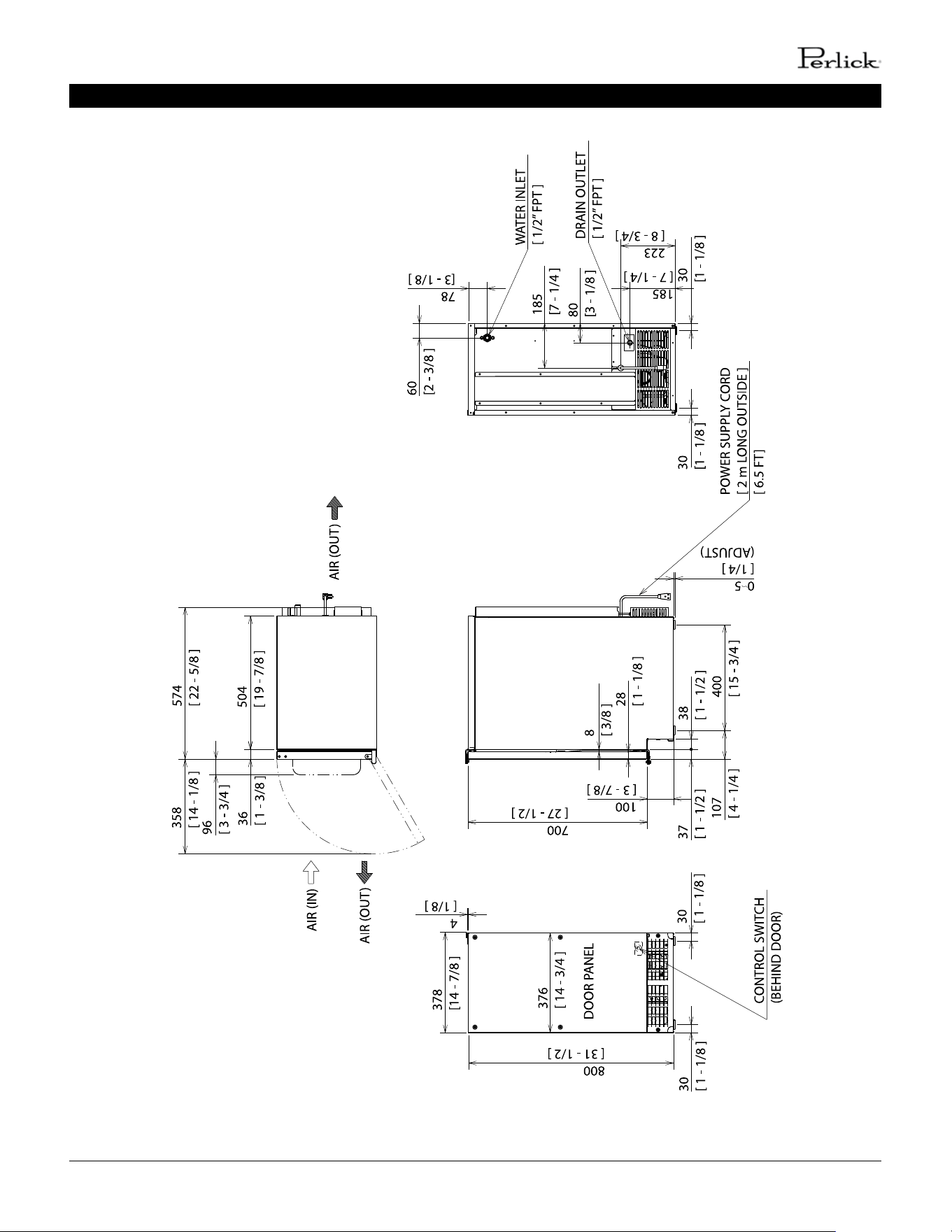
NICHE / PRODUCT DIMENSIONS / CONNECTIONS
perlick customer service (800)558-5592 | 9
PERLICK RESIDENTIAL ICE MAKER MANUAL
NICHE / PRODUCT DIMENSIONS / CONNECTIONS

10 | perlick.com/residential
PERLICK RESIDENTIAL ICE MAKER MANUAL
PRIOR TO INSTALLATION
The appliance must be installed in
accordance with applicable naonal, state, and local codes
and regulaons.
CHOKING HAZARD: Ensure all components,
fasteners, and thumbscrews are securely in place aer
installaon. Make sure that none have fallen into the storage
bin.
A. Checks Before Installaon
Visually inspect the exterior of the shipping container
and immediately report any damage to the carrier. Upon
opening the container, any concealed damage should also be
immediately reported to the carrier.
Remove the shipping carton, tape, and packing material. If any
are le in the appliance, it will not work properly.
Remove the package containing the accessories.
Remove the protecve plasc lm from the panels. If the
appliance is exposed to the sun or to heat, remove the lm
aer the appliance cools.
See the nameplate inside the storage bin, and check that your
voltage supplied corresponds with the voltage specied on the
nameplate.
B. Locaon
General
The appliance is approved for indoor or outdoor use.
Normal operang ambient temperature
must be within 45°F to 100°F (7°C to 38°C); Normal operang
water temperature must be within 45°F to 95°F (7°C to 35°C).
Operaon of the appliance, for extended periods, outside
of these normal temperature ranges may aect appliance
performance.
The appliance will not work at sub-freezing
temperatures. To prevent damage to the water supply line,
drain the appliance if the air temperature is going to go below
32°F (0°C). See “V. Preparing the Appliance for Periods of
Non-Use.”
The appliance should not be located next to ovens, grills, or
other high heat producing equipment.
The locaon must provide a rm and level foundaon for the
appliance.
DANGER
!
DANGER
!
The appliance requires no side or top clearance. But allow
enough space at rear for water supply and drain connecons
and at least 15” (38 cm) clearance at front.
The appliance must be at oor level on a nished oor even
if under a cabinet. In areas where water damage is a concern,
install in a contained area with a oor drain.
Do not let the weight of the counter rest on
the appliance.
Do not install the appliance in a corner where
the door will interfere with other equipment or where the
appliance cannot be pulled out for service.
WARNING
WARNING
WARNING
WARNING
perlick customer service (800)558-5592 | 11
PERLICK RESIDENTIAL ICE MAKER MANUAL
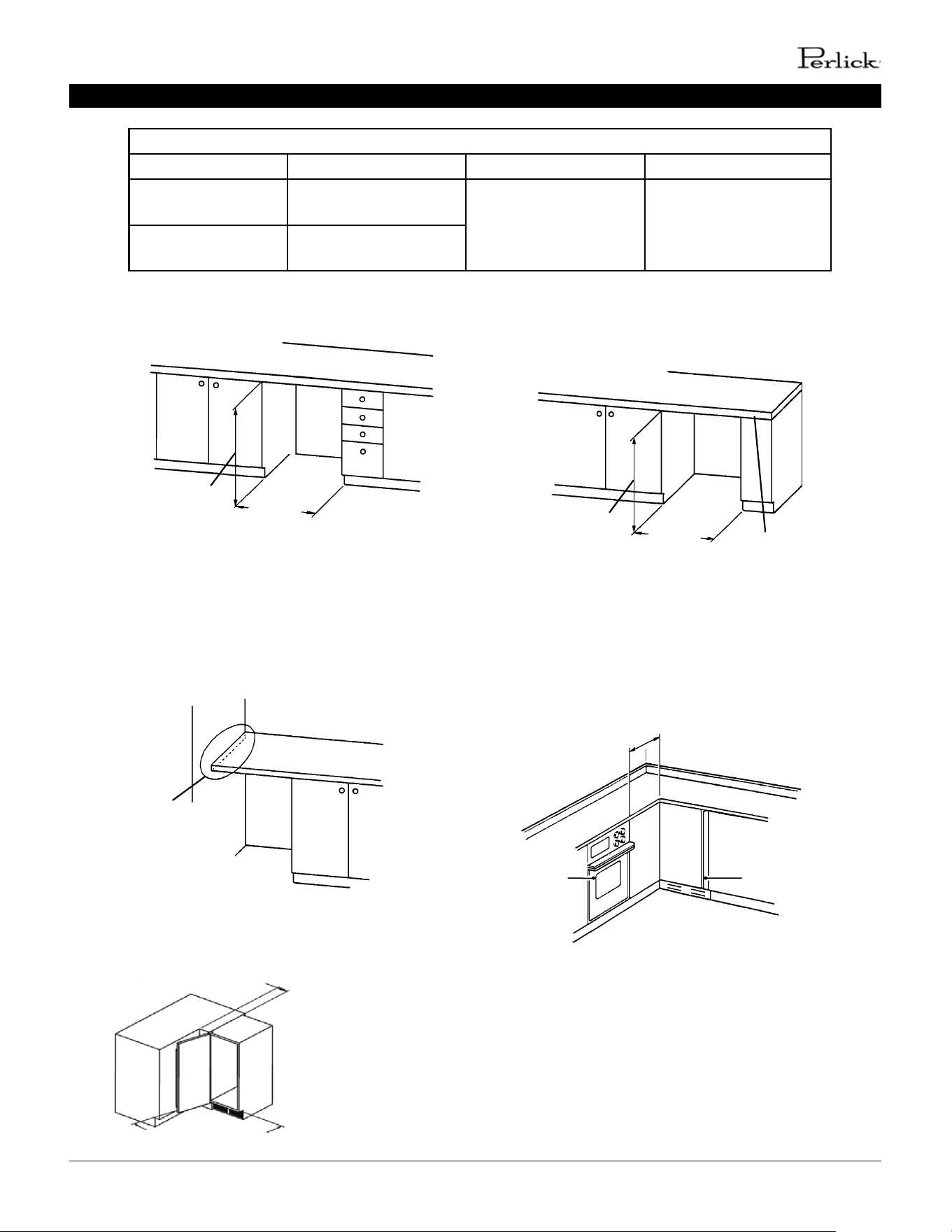
INSTALLATION INSTRUCTIONS
H50IMS-R/L
H50IMW
Min. 34"
(864 mm)
H50IMS-ADR/ADL
H50IMW-AD
Min. 32"
(814 mm)
Min. 15"
(381 mm)
Between Two Cabinets Between a Cabinet and
the End of a Counter
Support: Do not
let the weight of
the counter rest
on the appliance
Min. 15"
(381 mm)
H50IMS-R/L
H50IMW
Min. 34"
(864 mm)
H50IMS-ADR/ADL
H50IMW-AD
Min. 32"
(814 mm)
Min. 23"
(584 mm)
Oven
Appliance
Between a Cabinet and
a Wall or Tall Cabinet
In a Corner
Secure: Do not let
the weight of the
counter rest on
the icemaker
Installaon Space
Model Height Width Depth
H50IMS-R/L
H50IMW
34" (864 mm) minimum
15" (381 mm) minimum 24" (610 mm) minimum
H50IMS-ADR/ADL
H50IMW-AD
32" (814 mm) minimum
105° minimum door swing for
convenient access to ice bin
4-7/8” minimum distance from corner to
achieve desired door opening clearance
12 | perlick.com/residential
PERLICK RESIDENTIAL ICE MAKER MANUAL
INSTALLATION INSTRUCTIONS
2. H50IMW, H50IMW-AD
OVERLAY PANEL FABRICATION AND
ATTACHMENT
The overlay panel must be craed by a
professional cabinet maker to ensure quality results.
PARTS
Ensure that all parts required for the overlay panel
assembly are contained in the accessories bag.
CAUTION
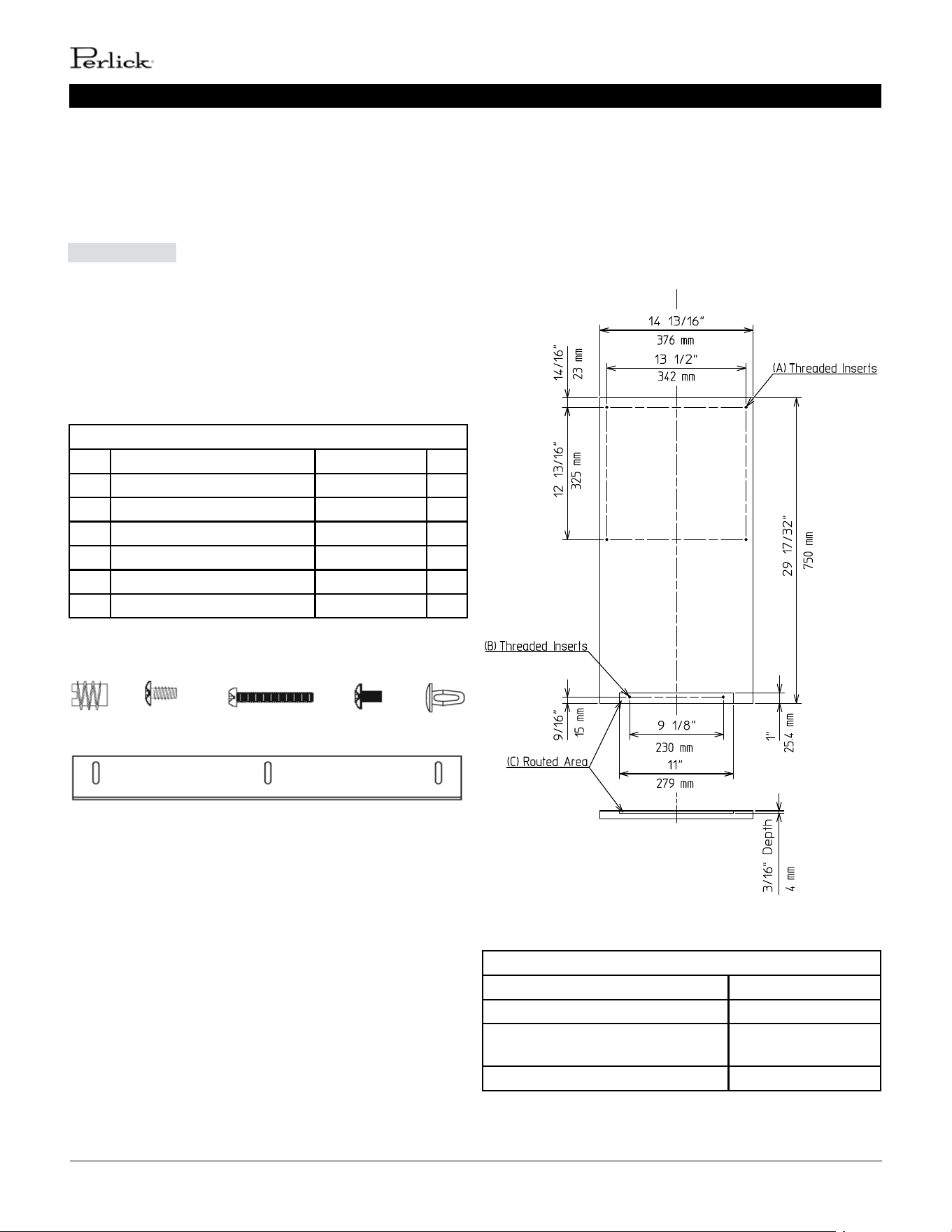
Overlay Panel Parts
No. Descripon Part Number Qty.
1 Threaded Wood Insert 4A4004-01 6
2 T2 Screw 4×8 SS 7P32-0408 3
3 Pan Head Screw M4×25 SS 7C12-0425 4
4 Truss Head Screw M4×8 SS 7C32-0408 2
5 Canoe Clip 4A5835-01 2
6 Sheet Metal Bracket 4A3998-01 1
1 2 3
4 5
6
OVERLAY PANEL SPECIFICATION
Use the specicaon that applies to your appliance
(H80CIMW or H80CIMW-AD) and the direcons that
follow to prepare your overlay panel.
(
)
(
)
(
)
(
)
(
)
(
)
(
)
(
)
(
)
(
)
H50IMW Overlay Panel Specicaon
Panel Height 29 17/32" (750 mm)
Panel Width 14 13/16" (376 mm)
Panel Thickness 5/8" (16 mm) min;
3/4" (19 mm) max
Panel and Door Weight (total) 20 lb. (9 kg) max
H50IMW
perlick customer service (800)558-5592 | 13
PERLICK RESIDENTIAL ICE MAKER MANUAL
INSTALLATION INSTRUCTIONS
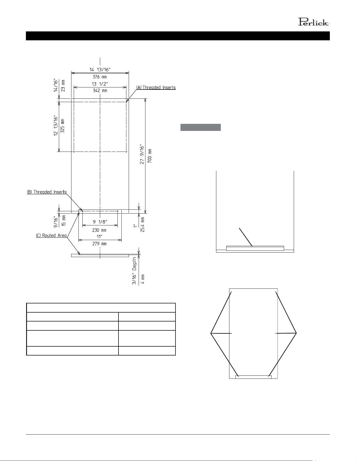
H50IMW-AD Overlay Panel Specicaon
Panel Height 27 9/16" (700 mm)
Panel Width 14 13/16" (376 mm)
Panel Thickness 5/8" (16 mm) min;
3/4" (19 mm) max
Panel and Door Weight (total) 20 lb. (9 kg) max
(
)
(
)
(
)
(
)
(
)
(
)
(
)
(
)
(
)
(
)
H50IMW-AD
FABRICATION OF OVERLAY PANEL
Fabricate the overlay panel as outlined in the specicaon on
the previous page and the instrucons below.
1. Rout a channel at the boom of the overlay panel
to the proper dimensions. See “(C) Routed Area” in the
specicaon diagram and Fig. 1.
2. Drill six 1/4” diameter (hardwood may require slightly
larger diameter) holes 3/8” (10 mm) deep in the
locaons designated.
Use care when drilling holes for mounng
hardware. All drilled holes must be straight and drilled to the
correct diameter and depth.
See “(A) Threaded Inserts” and “(B) Threaded Inserts” in
the specicaon diagram and Fig. 2.
WARNING
Routed Channel
Fig. 1
Fig. 2
Holes Holes
14 | perlick.com/residential
PERLICK RESIDENTIAL ICE MAKER MANUAL
3. Screw the 6 threaded wood inserts into the 1/4” holes
drilled in the previous step. Make sure that the inserts
are threaded straight and that the tops of the inserts
are ush to the overlay panel surface. Otherwise, the
overlay panel cannot be properly fastened to the door.
4. Mount the door handle hardware. Perlick recommends
that the door handle hardware be mounted on the
edge opposite of the door hinge side (oponal hinge
reversal is covered in step 6. Countersunk screw heads
are required to ensure that the hardware fasteners do
not interfere with the overlay panel ng ush with
the door.
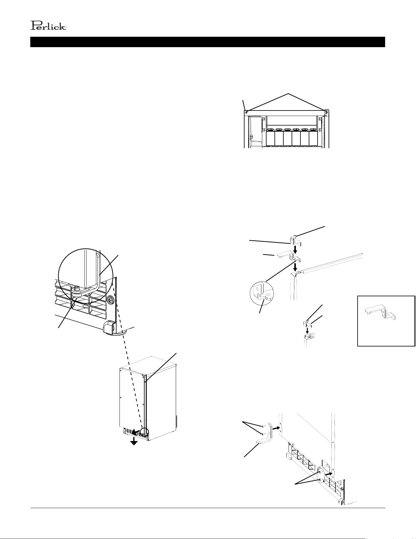
5. While maintaining a hold on the door, remove the
hinge stop pin from hinge (B). Pull out the boom of
the door slightly and gently remove the door from
hinge (A) (See Fig. 3). If you are leaving the door right
hinged, skip to step 7. If you would like to reverse the
door hinges, proceed to step 6.
Fig. 3
Hinge Stop Pin
Hinge (B)
Hinge (A)
INSTALLATION INSTRUCTIONS
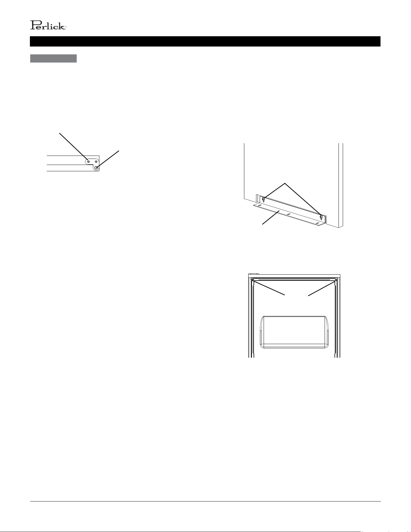
6. Remove hinge (A)-le from the accessory bag. Remove the
2 screws securing the top panel, then li it o. (See Fig. 4).
7. Remove hinge (A)-right and the bracket from the right
side of the unit. Set aside hinge (A)-right; it is not needed.
Remove the top brace from the le side. Fasten hinge (A)-
le and the bracket to the le side and the top brace to
the right side. See Fig. 5. Note: When on the proper side,
the gasket notch for hinge (A) is to the inside.
Hinge (A)-Right
Not Needed
Hinge (B)
Screws
Filler
Screws
Fig. 6
Fig. 4
Top Panel
Screws
Fig. 5
Gasket Notch
Bracket
Screw
Hinge (A) Le
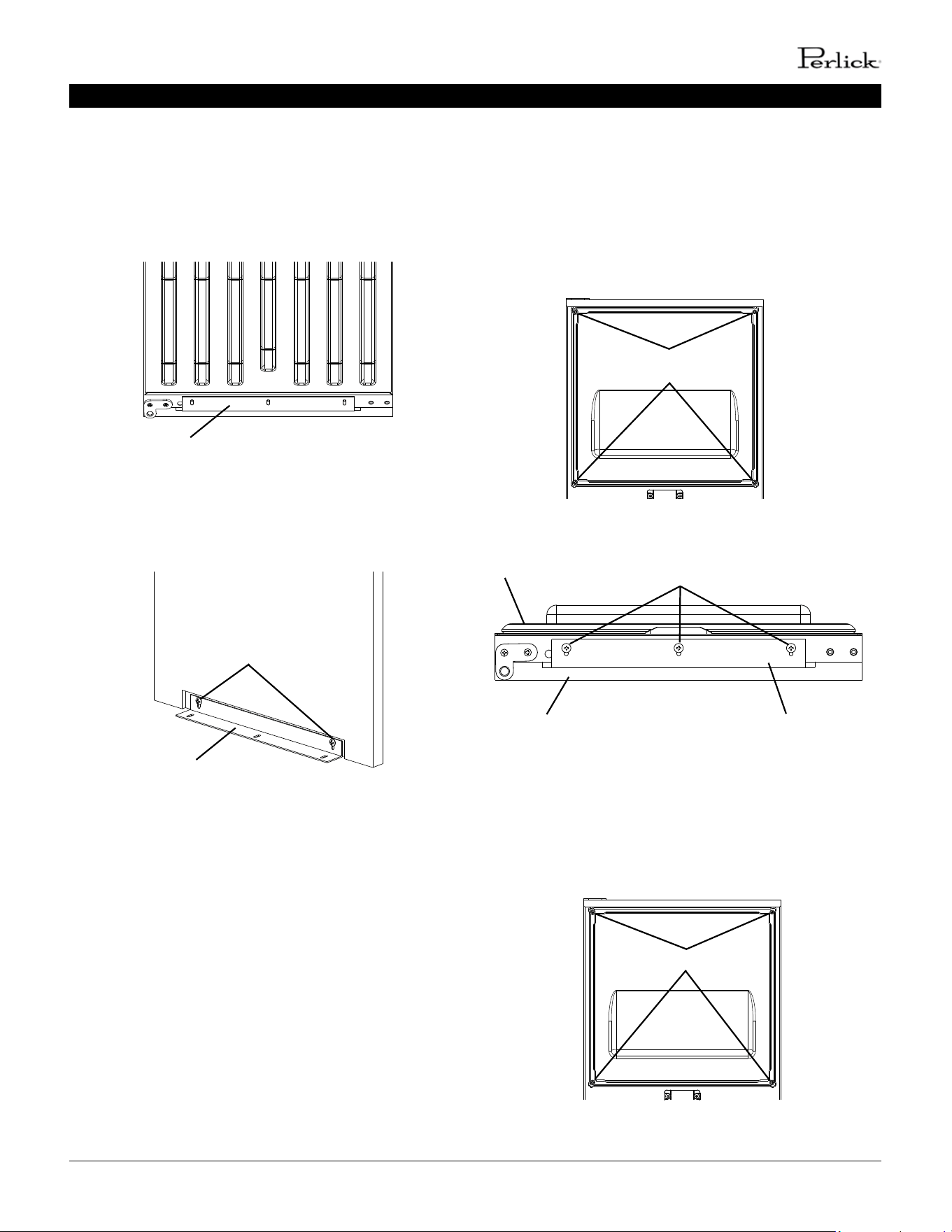
8. Remove hinge (B) from the right side of the unit and the 2
ller screws from the le side. Aach the 2 ller screws to
the right side and aach hinge (B) to the le side.
(See Fig. 6).
Screw
Top Brace
perlick customer service (800)558-5592 | 15
PERLICK RESIDENTIAL ICE MAKER MANUAL
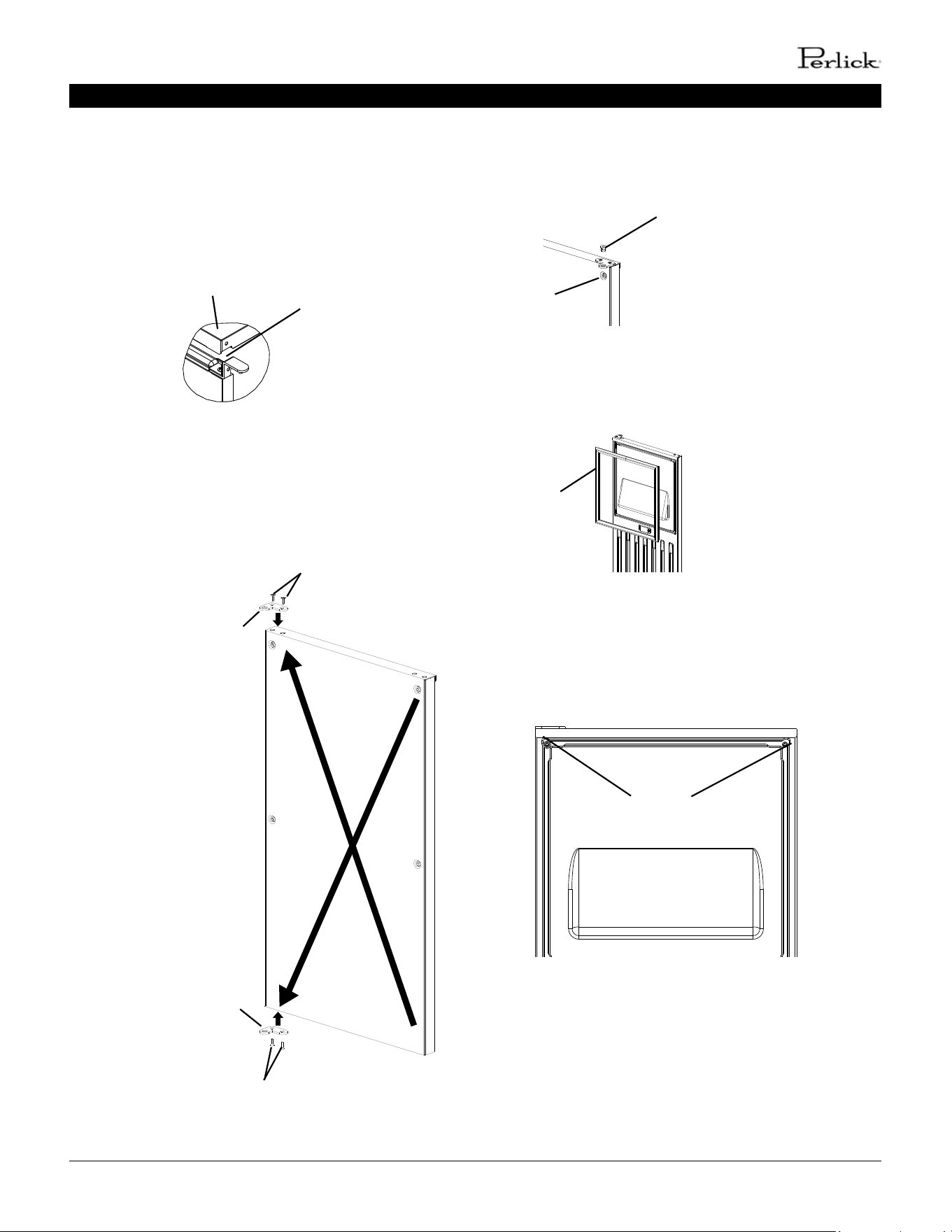
INSTALLATION INSTRUCTIONS
Fig. 7
Top Panel
Notch
Fig. 8
Screws
Hinge (C2)
Hinge (C1)
Screws
9. Rotate the top panel 180° from its previous posion. This
brings the notch that was previously in the right rear to
the le front. See Fig. 7. Hook the rear part of the panel
on the body, then secure the front with the 2 screws
removed in step 6a.
10. Remove hinge (C1) from the top right part of the door, ip
it and reaach to the boom le. Remove hinge (C2) from
the boom right part of the door, ip it and reaach to
the top le. See Fig. 8.
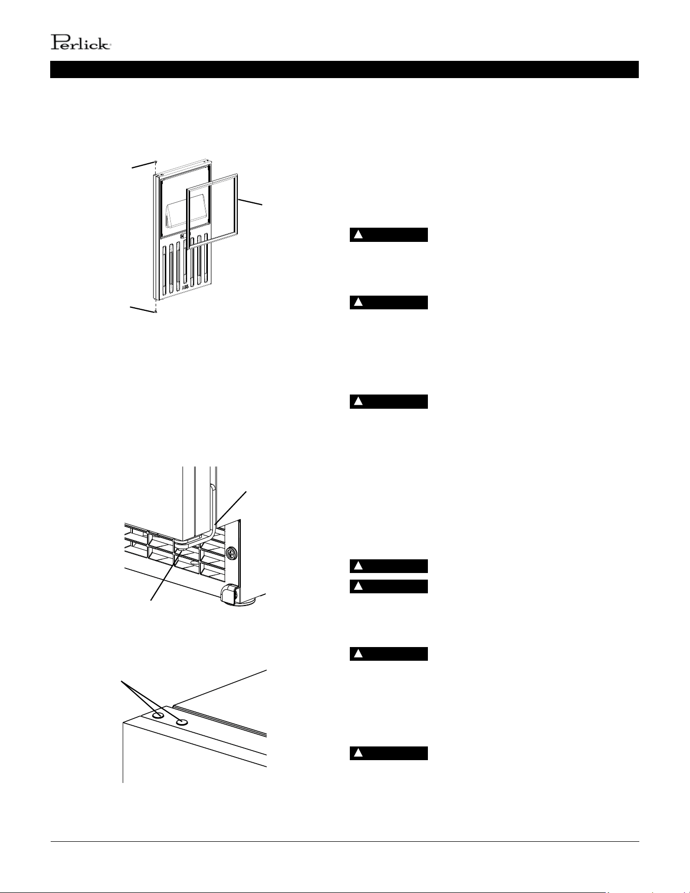
11. Remove the bushings from hinge (C1) and hinge (C2)
(the hinges aached to the door). See Fig. 9.
12. Remove the gasket from the door. See Fig. 10.
Fig. 11
Fig. 10
13. Temporarily fasten the overlay panel to the overlay
panel to the door using 2 of the M4x25 pan head screws
provided. See Fig. 11.
Fig. 9
Hinge
Bushing
Gasket
Screws
16 | perlick.com/residential
PERLICK RESIDENTIAL ICE MAKER MANUAL
INSTALLATION INSTRUCTIONS
Fig. 12
14. Mark the center point of the hinge (C1) and hinge (C2)
holes that extend over the overlay panel. See Fig. 12.
15. Remove the overlay panel from the door.
16. Drill 3/8” diameter holes 1/4” (7 mm) deep where you
marked on the overlay panel to accomodate the hinge
(C1) and hinge (C2) bushings.
Ensure that the back surface of overlay panel
is at before aaching.
WARNING
Mark the center point.
Hinge
ATTACHMENT OF OVERLAY PANEL TO
DOOR
1. Fasten the sheet metal bracket to the overlay panel
using the two M4×8 truss head screws provided. Snug
the screws, but do not ghten (See Fig. 13).
2. Temporarily fasten the overlay panel to the door using
2 of the M4×25 pan head screws provided (See Fig. 14).
Screws
Fig. 14
Fig. 13
Sheet Metal Bracket
Overlay Panel
Snug the screws,
but do not ghten.
perlick customer service (800)558-5592 | 17
PERLICK RESIDENTIAL ICE MAKER MANUAL
INSTALLATION INSTRUCTIONS
3. Adjust the sheet metal bracket so that it is ush with
the boom of the door (See Fig. 15).
4. Remove the overlay panel from the door and ghten
the two M4×8 truss head screws securing the sheet
metal bracket to the overlay panel (See Fig. 16).
Door
Sheet Metal Bracket
Fig. 15
Sheet Metal Bracket
Overlay Panel
Tighten the screws.
Fig. 16
5. Fasten the overlay panel to the door using the four
M4×25 pan head screws provided. Snug the screws,
but do not ghten (See Fig. 17).
6. Fasten the sheet metal bracket to the boom of the
door with the three T2 screws provided. Tighten the
screws to the door (See Fig. 18).
Snug the screws,
but do not ghten.
Fig. 17
Sheet Metal Bracket
Screws
Overlay Panel
Door
Fig. 18
7. Tighten the four M4×25 pan head screws installed in
step 5 (See Fig. 19).
Fig. 19
Tighten the screws.
18 | perlick.com/residential
PERLICK RESIDENTIAL ICE MAKER MANUAL
INSTALLATION INSTRUCTIONS / SETUP / ELECTRICAL CONNECTION
8. Replace the door gasket in its proper orientaon.
Reinsert the bushings into hinge (C1) and hinge (C2)
(the hinges aached to the door) (See Fig. 20).
Bushing
Bushing
Gasket
Fig. 20
9. Aach the door to hinge (A), then connue to maintain
a hold on the door. Screw the hinge stop pin into hinge
(B) unl it is ght (See Fig. 21).
10. Insert the 2 canoe clips included in the accessory bag
into the holes on top of the door (See Fig. 22).
Hinge Stop Pin
Hinge (B)
Fig. 21
Canoe Clips
Fig. 22
SETUP
1. Posion the appliance in the selected permanent
locaon.
2. Level the appliance from side-to-side and front-to-rear
by adjusng the feet.
ELECTRICAL CONNECTION
Electrical connecon must meet naonal,
state, and local electrical code requirements. Failure to meet
these code requirements could result in death, electric shock,
serious injury, re, or damage.
The appliance requires an independent
power supply of proper capacity. See the nameplate for
electrical specicaons. Failure to use an independent power
supply of proper capacity can result in a tripped breaker,
blown fuse, damage to exisng wiring, or component failure.
This could lead to heat generaon or re.
THE APPLIANCE MUST BE GROUNDED:
The appliance is equipped with a NEMA 5-15 three-prong
grounding plug to reduce the risk of potenal shock hazards.
It must be plugged into a properly grounded, independent
3-prong wall outlet. If the outlet is a 2-prong outlet, it is your
personal responsibility to have a qualied electrician replace
it with a properly grounded, independent 3-prong wall outlet.
Do not remove the ground prong from the power cord and
do not use an adapter plug. Failure to properly ground the
appliance could result in death or serious injury.
Do not use an extension cord.
To reduce the risk of electric shock, do not
touch the control switch or plug with damp hands. Make sure
the control switch is in the “OFF” posion before plugging in
or unplugging the appliance.
Do not use an appliance with a damaged
power cord. The power cord should not be altered, jerked,
bundled, weighed down, pinched, or tangled. Such acons
could result in electric shock or re. To unplug the appliance,
be sure to pull the plug, not the cord, and do not jerk the
cord.
The GREEN ground wire in the factory-
installed power cord is connected to the appliance. If it
becomes necessary to remove or replace the power cord, be
sure to connect the power cord’s ground wire to this screw
upon reaachment.
DANGER
!
DANGER
!
DANGER
!
DANGER
!
DANGER
!
DANGER
!
DANGER
!
perlick customer service (800)558-5592 | 19
PERLICK RESIDENTIAL ICE MAKER MANUAL
WATER SUPPLY AND DRAIN CONNECTIONS
A plumbing permit and services of a licensed plumber may be
required in some areas.
A water supply line shut-o valve and drain valve must be
installed.
Be sure there is sucient extra water supply line and drain line
for the appliance to be pulled out for service.
Drain line should not be piped directly to the sewer system.
Water line installaon to the appliance is not
warranted by Perlick.
Water-hammer issues must be resolved
by a qualied plumber before installing the appliance. Water
hammer can cause appliance damage that may lead to water
leakage or ooding.
A minimum of 1/2” nominal ID hard pipe
or equivalent is required for the drain line. Installing a smaller
diameter drain line will reduce water ow and may lead to
water leakage or ooding.
If using the oponal drain pump (63802A),
test its operaon every me the appliance is cleaned and
sanized. See “IV.E. Oponal Drain Pump 63802A” for details. If
the oponal drain pump is not operang properly, water could
back up and overow, leading to costly water damage.
Usually an electrical permit and services of a licensed electrician
are required.
The maximum allowable voltage variaon is ±10 percent of the
nameplate rang.
For oponal drain pump (63802A) installaon, refer to the
instrucons included with the pump.
WATER SUPPLY AND DRAIN
CONNECTIONS
Water supply and drain connecons must
be installed in accordance with applicable naonal, state, and
local regulaons.
Normal operang water temperature must be
within 45°F to 95°F (7°C to 35°C). Operaon of the appliance,
for extended periods, outside of this normal temperature range
may aect appliance performance.
Water supply pressure must be a minimum
of 10 PSIG and a maximum of 113 PSIG. If the pressure exceeds
113 PSIG, the use of a pressure reducing valve is required.
External lters, strainers, or soeners may be
required depending on water quality. Contact your local Perlick
Cered Service Representave or local Perlick distributor for
recommendaons.
Connect to potable water supply only. Do not
connect to a hot-water supply.
In areas where water damage is a concern,
install in a contained area with a oor drain.
WARNING
DANGER
!
WARNING
WARNING
WARNING
WARNING
Water Supply Inlet Minimum Water Supply Line Size Drain Outlet Minimum Drain Line Size
1/2" Female Pipe Thread (FPT) 1/4" Nominal ID Copper
Water Tubing or Equivalent
1/2" Female Pipe Thread (FPT) 1/2" Nominal ID
Hard Pipe or Equivalent
WARNING
WARNING
WARNING
WARNING
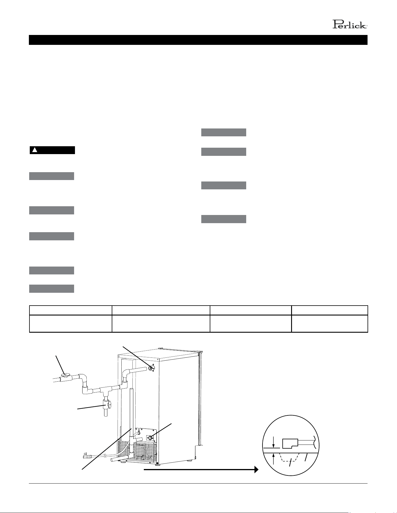
Fig. 23
Piping to approved drain. Leave a 2-inch (5-cm)
vercal air gap between the end of the pipe and
the drain.
2-inch (5-cm)
air gap
Floor
Drain
Shut-O Valve
Drain Valve
Water Supply Inlet
1/2" FPT
Drain Outlet
1/2" FPT
Vented Tee Connecon
Be sure there is sucient extra water supply line
and drain line for the appliance to be pulled out
for service.
20 | perlick.com/residential
PERLICK RESIDENTIAL ICE MAKER MANUAL
WATER SUPPLY AND DRAIN CONNECTIONS / FINAL CHECKLIST / STARTUP
An air gap of a minimum of 2 vercal inches (5 cm) must be
between the end of the drain pipe from the appliance and the
oor drain.
For gravity drain installaon, drain must have 1/4” fall per foot
(2 cm per 1 m) on horizontal runs to get good ow. A vented
tee connecon is also required for proper ow. Extend the vent
at least 12” (30 cm) above the drain outlet. For oponal drain
pump (63802A) installaon, refer to the instrucons included
with the pump.
FINAL CHECKLIST
CHOKING HAZARD: Ensure all components,
fasteners, and thumbscrews are securely in place aer
installaon. Make sure that none have fallen into the
storage bin.
1. Is the appliance level?
2. Is the appliance in a site where the ambient temperature
is within 45°F to 100°F (7°C to 38°C) and the water
temperature within 45°F to 95°F (7°C to 35°C) all year
around?
3. Have the shipping carton, tape, and packing material been
removed from the appliance? Has the protecve plasc
lm been removed from the panels?
4. Have all electrical and water connecons been made? Do
electrical and water connecons meet all naonal, state,
and local code and regulaon requirements?
5. Has the power supply voltage been checked or tested
against the nameplate rang? Is the power supply a
properly grounded, independent 3-prong wall outlet?
6. Are the water supply and drain lines sized as specied?
Are the water supply line shut-o valve and drain valve
installed? Has the water supply pressure been checked to
ensure a minimum of 10 PSIG and a maximum of 113 PSIG?
7. Are all components, fasteners, and thumbscrews securely
in place?
8. Has the end user been given this instrucon manual,
and instructed on how to operate the appliance and the
importance of the recommended periodic maintenance?
9. Has the end user been given the name and telephone
number of an authorized service agent?
10. Has the warranty tag been lled out and forwarded to the
factory for warranty registraon?
DANGER
!
STARTUP
All parts are factory-adjusted. Improper
adjustments may adversely aect safety, performance,
component life, and warranty coverage.
If the appliance is turned o, wait for at least
3 minutes before restarng the appliance to prevent damage to
the compressor.
At startup, conrm that all internal and
external connecons are free of leaks.
1. Open the water supply line shut-o valve.
2. Make sure the control switch is in the “OFF” posion. Plug
the appliance into the electrical outlet.
To reduce the risk of electric shock, do not
touch the control switch or plug with damp hands. If you
have to slide the appliance back for a built-in installaon,
make sure you do not damage or pinch the water supply line,
drain line, or power cord.
3. If required by sanitaon code in your area, seal the
perimeter where the appliance touches the oor with
approved caulk compound in a smooth and easily cleanable
manner.
4. Move the control switch to the “ICE” posion to start the
automac ice making process.
5. Once the appliance starts to produce ice, allow it to run for
another 30 minutes.
6. Move the control switch to the “OFF” posion.
DANGER
!
WARNING
WARNING
DANGER
!
perlick customer service (800)558-5592 | 21
PERLICK RESIDENTIAL ICE MAKER MANUAL
STARTUP / MAINTENANCE
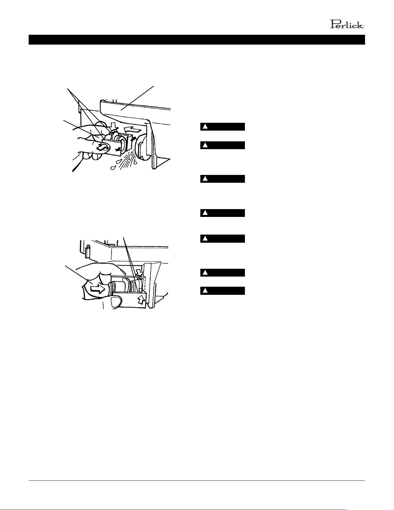
7. Inside the storage bin, disconnect the sucon tube by
squeezing the tabs and pulling the tube clear. See Fig. 24.
Allow the water tank to drain.
8. Reconnect the sucon tube as illustrated. See Fig. 25. Make
sure the tabs lock into place; a loose ng may cause a
water leak.
9. Remove the ice produced, then clean the storage bin liner,
door liner, and door gasket using a neutral cleaner. Rinse
thoroughly aer cleaning.
10. Move the control switch to the “ICE” posion to start the
automac ice making process.
11. To conrm bin control operaon, hold ice in contact with
the bin control thermostat bulb. If the icemaker does not
stop within 10 seconds, the bin control thermostat must be
adjusted. Installaons at higher altude locaons are more
likely to require adjustment.
Sucon Tube
Tabs
Water Tank
Drain
Fig. 24
Sucon Tube
Tabs
Fig. 25
MAINTENANCE
The appliance must be maintained in accordance with the
instrucon manual and labels provided with the appliance.
Consult with your local Perlick Cered Service Representave
about maintenance service. To obtain the name and phone
number of your local Perlick Cered Service Representave,
visit www.perlick.com.
Only qualied service technicians should
service the appliance.
Failure to install, operate, and maintain the
equipment in accordance with this manual will adversely
aect safety, performance, component life, and warranty
coverage.
To reduce the risk of electric shock, do not
touch the control switch or plug with damp hands. Make sure
the control switch is in the “OFF” posion before plugging in
or unplugging the appliance.
Move the control switch to the “OFF”
posion and unplug the appliance from the electrical outlet
before servicing.
CHOKING HAZARD: Ensure all components,
fasteners, and thumbscrews are securely in place aer any
maintenance is done to the appliance. Make sure that none
have fallen into the storage bin.
Do not place ngers or any other objects
into the ice discharge opening.
Aer service, make sure that there are no
wires pinched between the panels and appliance. Make sure
you do not damage or pinch the water supply line, drain line,
or power cord.
DANGER
!
DANGER
!
DANGER
!
DANGER
!
DANGER
!
DANGER
!
DANGER
!
22 | perlick.com/residential
PERLICK RESIDENTIAL ICE MAKER MANUAL
MAINTENANCE
CLEANING AND SANITIZING
INSTRUCTIONS
The appliance must be cleaned and sanized at least once a
year. More frequent cleaning and sanizing may be required
in some condions.
To prevent injury to individuals and damage
to the appliance, do not use ammonia type cleaners.
Carefully follow any instrucons provided
with the cleaning and sanizing soluons.
Always wear liquid-proof gloves and goggles
to prevent the cleaning and sanizing soluons from coming
into contact with skin or eyes.
DANGER
!
DANGER
!
DANGER
!
Do not use ice made from the cleaning and
sanizing soluons. Aer cleaning and sanizing, be careful
not to leave any soluon in the appliance.
Do not place ngers or any other objects
into the ice discharge opening (extruding head).
DANGER
!
DANGER
!
1. Cleaning Soluon
Dilute 4 . oz. (118 ml or 8 tbs) of Nu-Calgon “Liquid Ice
Machine Cleaner” with 1 gal (3.8 l) of warm water. This is
a minimum amount. Make more soluon if necessary. It is
recommended that cleaning be performed by a qualied
service technician.
For safety and maximum eecveness, use
the soluon immediately aer diluon.
2. Cleaning Procedure
1. Remove all ice from the storage bin.
Note: To remove cubes on the evaporator, move the
control switch to the “OFF” posion and then
move it back to the “ICE” posion aer 3
minutes. The harvest cycle starts and the cubes
will be removed from the evaporator.
2. Move the control switch to the “OFF” posion.
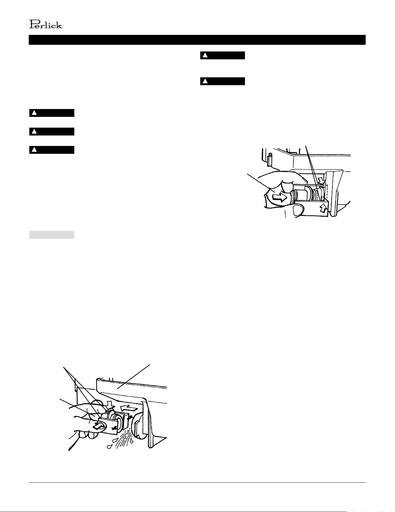
3. Inside the storage bin, disconnect the sucon tube by
` squeezing the tabs and pulling the tube clear.
See Fig. 26. Allow the water tank to drain.
4. Reconnect the sucon tube as illustrated. See Fig. 27.
Make sure the tabs lock into place; a loose ng may
cause a water leak.
5. Slowly pour the cleaning soluon into the water tank.
6. Move the control switch to the “WASH” posion.
7. Allow the cleaning soluon to circulate for 30 minutes,
then move the control switch to the “OFF” posion.
8. Disconnect the sucon tube. Allow the water tank to
drain, then reconnect the sucon tube.
9. Move the control switch to the “ICE” posion and
allow the icemaker to operate for 2 minutes.
This allows the water tank to ll with water.
10. Move the control switch to the “WASH” posion.
11. Allow the water to circulate for 5 minutes, then move
the control switch to the “OFF” posion.
12. Disconnect the sucon tube. Allow the water tank
to drain, then reconnect the sucon tube.
13. Repeat steps 9 through 12 three more mes to rinse
thoroughly.
Note: If you do not sanize the appliance, go to step 8 in “IV.B.5.
Sanizing Procedure - Final.”
CAUTION
Sucon Tube
Tabs
Water Tank
Drain
Fig. 26
Sucon Tube
Tabs
Fig. 27
perlick customer service (800)558-5592 | 23
PERLICK RESIDENTIAL ICE MAKER MANUAL
MAINTENANCE
3. Sanizing Soluon
Dilute 0.5 . oz. (14.8 ml or 1 tbs) of a 5.25% sodium
hypochlorite soluon (chlorine bleach) with 1 gallon
(3.8 l) of warm water. This is a minimum amount. Make
more soluon if necessary. Using a chlorine test strip or
other method, conrm that you have a concentraon
of about 200 ppm.
For safety and maximum eecveness, use
the soluon immediately aer diluon.
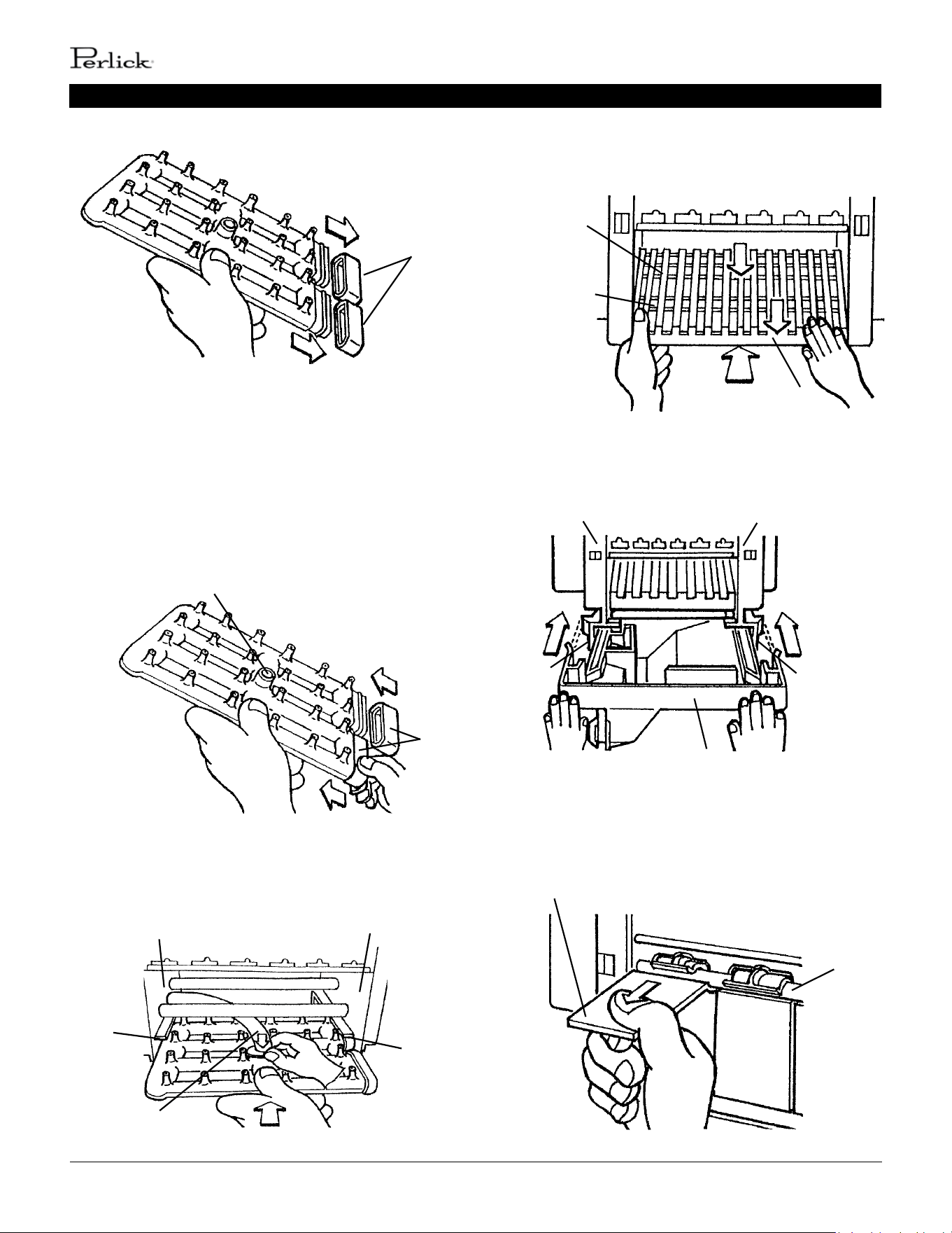
4. Sanizing Procedure
1. Make sure the control switch is in the “OFF” posion
and the storage bin is empty.
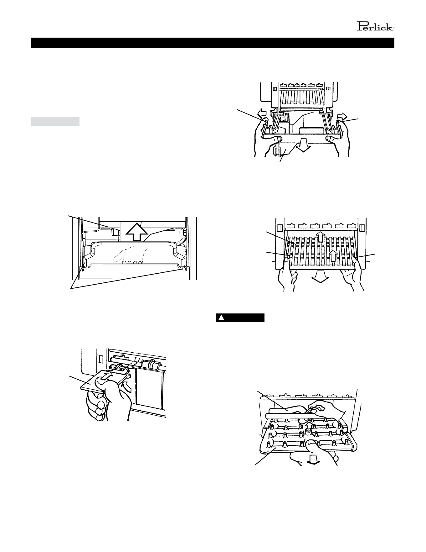
2. Remove the slope from the storage bin by carefully
bending it in the center and releasing it from the 2
slope shas. See Fig. 28.
3. Remove each separator by liing it to the horizontal
posion and pushing it hard inward. See Fig. 29.
4. Disconnect the sucon tube. Allow the water tank to
drain.
5. Spread out the tabs to unlock the water tank, them
slide it out. See Fig. 30.
6. Li o the ice chute from the frame pipe and
then from the rear frame pipe. See Fig. 31.
Ensure all components, fasteners, and
thumbscrews are securely in place. Make sure that none have
fallen into the storage bin.
7. Disconnect the discharge tube from the spray
assembly, then slide out the spray assembly.
See Fig. 32.
CAUTION
Separator
Fig. 29
Tab
Fig. 30
Tab
Water Tank
Rear Frame Pipe
Fig. 31
Ice Chute
Front Frame Pipe
Slope
Fig. 28
Slope Shas
Fig. 32
Discharge Tube
Spray Assembly
DANGER
!
24 | perlick.com/residential
PERLICK RESIDENTIAL ICE MAKER MANUAL
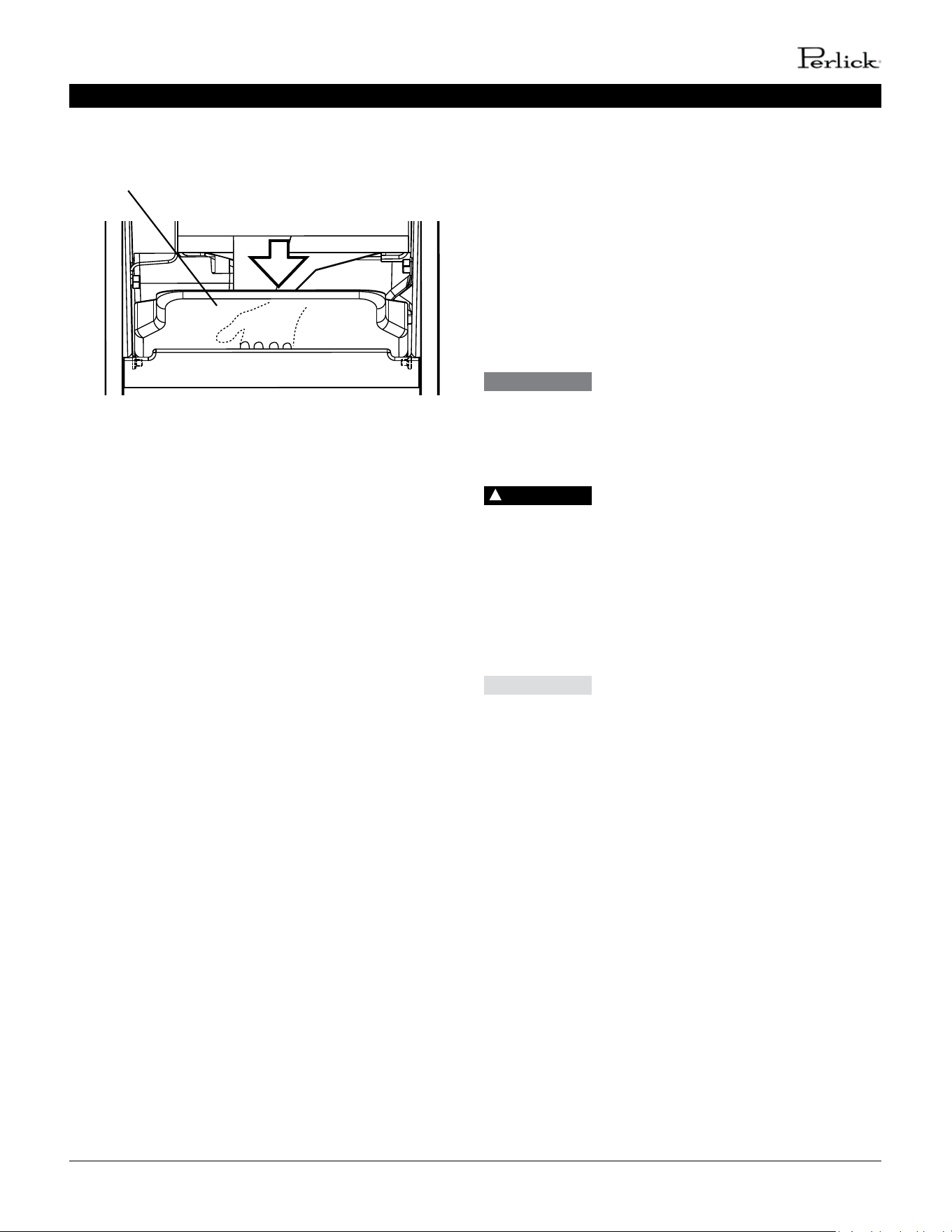
MAINTENANCE
8. Remove the two caps. See Fig. 33.
9. Soak all of the removed parts and the scoop in the
sanizing soluon for 10 minutes. If the spray
assembly nozzles are clogged, clean them with a wire
or a suitable brush.
10. Rinse the parts thoroughly with clean water.
11. Ret the 2 caps in their correct posions. Make sure
the reducing pipe is in place in the center.
See Fig. 34.
12. Slide in the spray assembly along the rails on the le
and right brackets. See Fig. 35. Connect the discharge
tube securely to the spray assembly; a loose ng
may cause a water leak.
13. Posion and lock the ice chute onto the front and rear
frame pipes by pushing the ice chute down unl it
clicks onto both frame pipes. See Fig. 36.
14. Slide in the water tank along the rails at the boom of
the le and right brackets unl it locks into place.
See Fig. 37.
15. Reconnect the sucon tube.
16. Hook each separator onto the rail, then pull it hard
towards you unl it locks into place. See Fig. 38.
Fig. 33
Caps
Fig. 34
Caps
Reducing Pipe
Le Bracket Right Bracket
Rail
Rail
Discharge Tube
Fig. 35
Ice Chute
Rear Frame Pipe
Front Frame Pipe
Fig. 36
Fig. 37
Le Bracket
Right Bracket
Rail Rail
Water Tank
Rail
Separator
Fig. 38
perlick customer service (800)558-5592 | 25
PERLICK RESIDENTIAL ICE MAKER MANUAL
17. Replace the slope in its correct posion. See Fig. 39.
18. Discard the sanizing soluon.
19. Mix a new batch of the sanizing soluon and slowly
pour it into the water tank.
20. Move the control switch to the “WASH” posion.
21. Aer circulang the sanizing soluon for 15 minutes,
move the control switch to the “OFF” posion.
22. Disconnect the sucon tube. Allow the water tank to
drain, then reconnect the sucon tube.
23. Repeat steps 19 through 22 one me.
24. Move the control switch to the “ICE” posion and
allow the icemaker to operate for 2 minutes.
This allows the water tank to ll with water.
25. Move the control switch to the “WASH” posion.
26. Allow the water to circulate for 5 minutes, then move
the control switch to the “OFF” posion.
27. Disconnect the sucon tube. Allow the water tank to
drain, then reconnect the sucon tube.
28. Repeat steps 24 through 27 two more mes to rinse
thoroughly.
29. Clean the storage bin liner, door liner, and door gasket
with a neutral cleaner. Rinse thoroughly aer cleaning.
30. Move the control switch to the “ICE” posion to start
the automac ice making process.
Slope
Fig. 39
MAINTENANCE
STAINLESS STEEL EXTERIOR
To prevent corrosion, wipe the exterior occasionally with a
clean and so cloth. Use a damp cloth containing a neutral
cleaner to wipe o oil or dirt build up.
STORAGE BIN DRAIN
In some condions, slime may build up inside the storage bin
drain and prevent water from draining properly. To prevent this
buildup, perform the following procedure once every 3 months
or as oen as necessary for condions.
If the storage bin drain becomes clogged,
water could build up in the bin and overow, leading to costly
water damage.
1. Move the control switch to the “OFF” posion
To reduce the risk of electric shock, do not
touch the control switch with damp hands.
2. Remove all ice from the storage bin.
3. Mix a batch of sanizing soluon by dilung
1.25 .oz. (37 ml or 2.5 tbs) of a 5.25% sodium
hypochlorite soluon (chlorine bleach) with
2.5 gallons (9.5 l) of warm water. Using a chlorine test
strip or other method, conrm that you have a
concentraon of about 200 ppm.
For safety and maximum eecveness, use
the soluon immediately aer diluon.
4. Slowly pour the sanizing soluon into the
storage bin.
5. Aer all of the soluon has drained, clean the storage
bin liner with a neutral cleaner. Rinse thoroughly with
clean water.
6. Move the control switch to the “ICE” posion to start
the automac ice making process.
DANGER
!
CAUTION
WARNING
26 | perlick.com/residential
PERLICK RESIDENTIAL ICE MAKER MANUAL
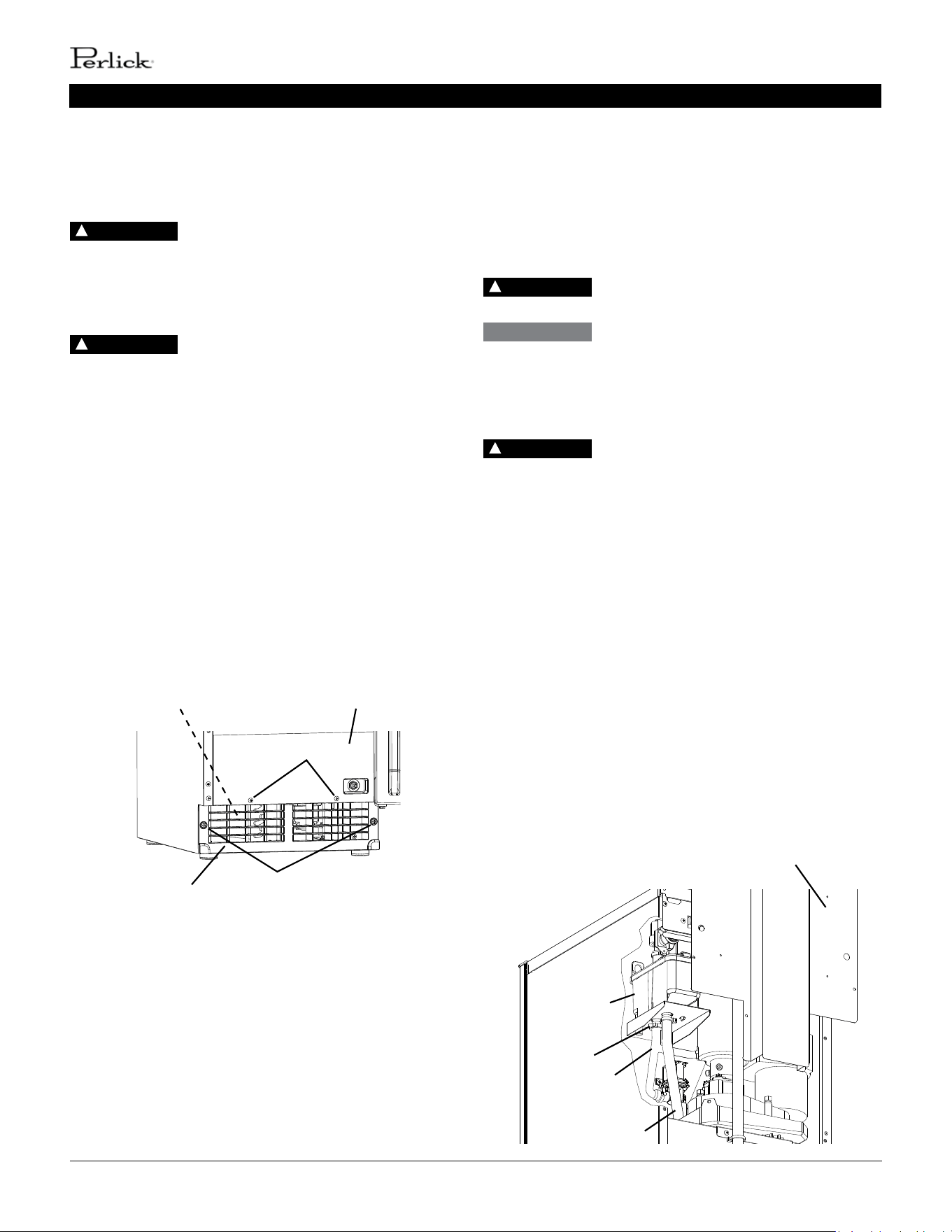
CONDENSER
Check the condenser once a year, and clean if required by
following the steps below. More frequent cleaning may be
required depending on locaon.
Condenser ns are sharp. Use care when
cleaning.
1. Move the control switch to the “OFF” posion, then
unplug the appliance from the electrical outlet
To reduce the risk of electric shock, do not
touch the control switch or plug with damp hands.
2. Remove the screws securing the front panel, then
remove it (See Fig. 40).
3. Remove the screws securing the louver, then
remove it.
4. Use a brush aachment on a vacuum cleaner to gently
clean the condenser ns. Do not use too much force,
otherwise the ns could be damaged.
5. Replace the louver and front panel in their correct
posions. Ensure that the screws are securely in place.
6. Plug the appliance back in. Move the control switch to
the “ICE” posion to start the automac ice making
process.
DANGER
!
Front Panel
Louver
Fig. 40
Screws
Screws
Condenser
DANGER
!
MAINTENANCE / PREPARING THE APPLIANCE FOR PERIODS OF NON-USE
PREPARING THE APPLIANCE FOR
PERIODS OF NON-USE
During extended periods of non-use, extended absences, or in
sub-freezing temperatures, follow the instrucons below. When
the appliance is not used for two or three days under normal
condions, it is sucient to move the control switch to the
“OFF” posion.
Only qualied service technicians should
service the appliance.
During extended periods of non-use,
extended absences, or in sub-freezing temperatures, follow the
instrucons below to reduce the risk of costly water damage.
1. Move the control switch to the “OFF” posion.
To reduce the risk of electric shock, do not
touch the control switch or plug with damp hands.
2. Close the water supply line shut-o valve, then open
the water supply line drain valve. See Fig. 31.
3. Allow the line to drain by gravity.
4. Move the control switch to the “DRAIN” posion.
5. Allow the water system to drain for 1 minute.
6. Aach a compressed air or carbon dioxide supply to
the water supply line drain valve.
7. Move the control switch to the “ICE” posion.
8. Blow the water supply line out using the compressed
air or carbon dioxide supply.
9. Close the water supply line drain valve.
10. Move the control switch to the “OFF” posion, then
unplug the appliance from the electrical outlet.
11. Remove the screws securing the upper rear panel,
then remove it (See Fig. 41).
DANGER
!
WARNING
DANGER
!
Fig. 41
Upper Rear Panel
Clamp
Reservoir
Outlet
Hose
Reservoir
Overow Hose

perlick customer service (800)558-5592 | 27
PERLICK RESIDENTIAL ICE MAKER MANUAL
12. Remove the clamp securing the reservoir outlet hose
to the reservoir. Disconnect the reservoir outlet hose
from the reservoir.
13. Aach a compressed air or carbon dioxide supply to
the reservoir outlet hose.
14. Plug the appliance back in, then move the control
switch to the “DRAIN” posion.
15. Blow out the reservoir outlet hose using the
compressed air or carbon dioxide supply.
16. Move the control switch to the “OFF” posion, then
unplug the appliance from the electrical outlet.
17. Reconnect the reservoir outlet hose to the reservoir,
then secure with the clamp. Make sure all hoses are
connected and secure.
18. Replace the rear panel in its correct posion.
19. Clean the storage bin by using a neutral cleaner. Rinse
thoroughly aer cleaning.
PREPARING THE APPLIANCE FOR PERIODS OF NON-USE / WARRANTY INFORMATION
WARRANTY
ENTIRE PRODUCT
Full One Year Warranty
For one year from the date of original installaon, Perlick
Corporaon’s warranty covers all parts and labor to repair or
replace any part of the product, which proves to be defecve in
material and workmanship.
TERMS
The Perlick Warranty applies to products installed in the y
United States, the District of Columbia or the ten provinces of
Canada.
All service provided by Perlick Corporaon under the above
warranty must be performed by authorized Perlick service
representaves, unless otherwise specied by Perlick.
Service will be provided in the home during normal business
hours.
This warranty is extended only to the original purchaser of the
Perlick product.
The above warranty does not apply if:
• Failure of product was due to transportaon
• Product was: improperly installed, misused, abused,
operang with low voltage, wiring not conforming electrical
codes, improperly maintained or modied.
• The original Bill of Sale, delivery date or serial number cannot
be veried.
• Defecve parts are not returned for inspecon if so required
by the Perlick Corporaon.
To receive parts and or service and the name of the
nearest Perlick authorized service representave, contact
your Perlick dealer, distributor or Perlick Corporaon’s
Technical Service Department; 8300 West Good Hope Road,
Milwaukee, Wisconsin 53223; call 800-558-5592, E-mail us at
warr[email protected], or visit our web:
www.perlick.com
This limited warranty is in lieu of any other warranty, expressed
or implied, including, but not limited to any implied warranty
of merchantability or tness for a parcular purpose; provided
however, that to the extent required by law, implied warranes
are included but do not extend beyond the duraon of the
express warranty rst set above. Perlick’s sole liability and
your exclusive remedy under this warranty are set forth in
the inial paragraph above. Perlick Corporaon shall have
no liability whatsoever for any incidental, consequenal or
special damages arising from the sale, use or installaon of the
product or from any other causes whatsoever, whether based
on warranty (expressed or implied) or otherwise based on
contract, tort or any other theory of liability.
Some states do not allow limitaons on how long an implied
warranty lasts or the exclusion or limitaon of incidental or
consequenal damages, so the above limitaons may not apply
to you. This warranty gives you specic legal rights, and you
may also have other rights, which vary, from state to state.
REGISTRATION
To register your Perlick product, visit our website at
www.perlick.com/RegisterMyPerlick and ll out the form.
Once completed, click on the ‘Submit Warranty Registraon’. Be
sure to register your product immediately upon installaon to
receive the warranty from installaon date instead of shipment
date. If le blank, the date will revert back to shipment date.

FORM NO. Z2517
REV. D-10/03/2018
8300 West Good Hope Road, Milwaukee, WI 53223, USA
perlick.com/residenal • (800) 558-5592
Perlick Residential is a division of Perlick Corporation
© 2018 Perlick Corporation
