Fase 1/Phase 1/Fase 1/Phase 1
-
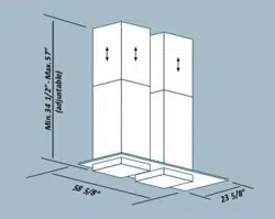
Individuare lʼaltezza (H1=65)desiderata per il posizionamento della cappa.
- Far scorrere i tralicci (C) e (C1) fino ad ottenere lʼaltezza desiderata (H2), succes-
sivamente bloccarli con 8 viti (V2) autofilettanti
(Fig.1a).
- Fissare il traliccio (C) al soffitto utilizzando 4 fischer da Ø 8 e relative viti (V1)
(Fig.1b).
- Fissare la parete superiore (C2) con 2 viti autofilettanti (V2).
Le due viti poste superiormente sono già state pre-avvitate.
- Identify the desired height (H1=65) for the positioning of the hood.
- Slide the lattice-works (C) and (C1) to the desired height (H2), then block them
with the 8 self-threading screws (V2) (Fig.1a).
- Fasten the lattice-work (C) to the ceiling using the four Ø 8 expansion plugs and
relative screws(V1) (Fig.1b).
- Fasten the upper panel (C2) with 2 self-threading screws (V2).
The two upper screws have already been pre-tightened.
-
Determinar la altura (H1=65) requerida para la colocación de la campana.
- Deslizar los bastidores (C) y (C1) hasta que se consiga la altura requerida (H2),
sucesivamente fijarlos con 4 tornillos (V2) autorroscantes
(Fig.1a).
- Fijar el bastidor (C) en el techo utilizando 8 tacos fischer de Ø 8 y los tornillos
correspondientes (V1) (Fig.1b).
- Fijar el bastidor superior (C2) con 2 tornillos autorroscantes (V2).
Los dos tornillos situados arriba ya se habrán enroscado previamente.
-
Die gewünschte Höhe (H1=65) für die Anbringung der Abzugshaube festlegen.
- Die Hängegerüste (C) und (C1) auf die gewünschte Höhe bringen (H2) und mit
8 gewindeformenden Schrauben (V2) befestigen (Abb.1a).
- Das Hängegerüst (C) mit 4 Fischerdübeln Ø 8 mm und den jeweiligen Schrauben
(V1) an der Decke anbringen (Abb.1b).
- Die obere Trägerplatte (C2) mit 2 Gewindeschrauben (V2) befestigen.
Die beiden oben liegenden Schrauben wurden bereits eingeschraubt.
Fig. 2
C2
H1
H
H2
Ø8
Ø8
Fig.1b
Abb.1b
Fig.1a
Abb.1a
C1
C
V1
V2
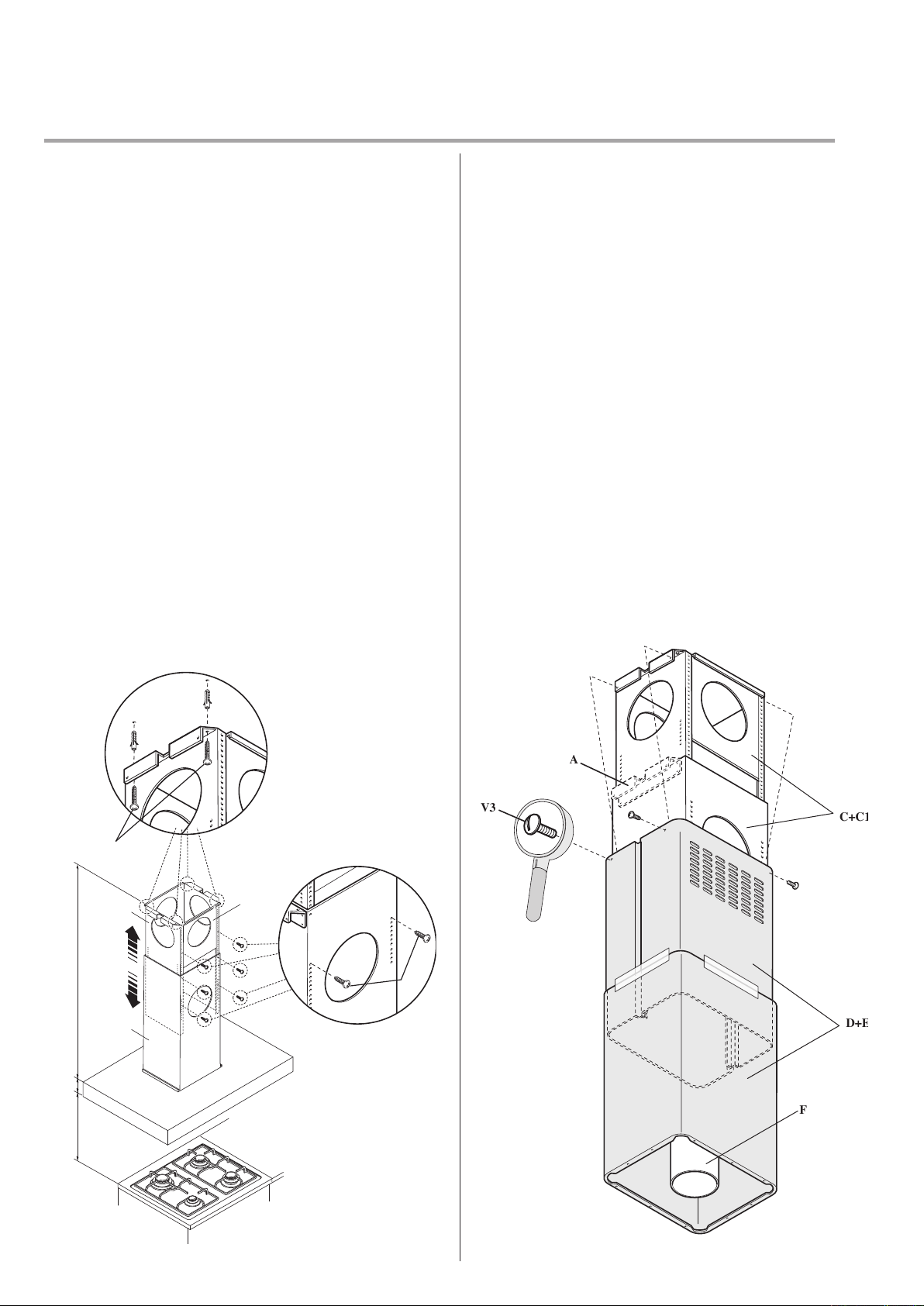
Fase 2/Phase 2/Fase 2/Phase 2
-
Infilare la prolunga sul camino e bloccarli tra loro con dello scotch di carta (Fig. 2).
- Fissare lʼassieme camino-prolunga (D+E) al traliccio (C) tramite le 4 viti metriche
M4 (V3) inserite nei fori già esistenti senza bloccarle definitivamente
(Fig. 2).
- Nel caso di versione aspirante: individuare lʼaltezza ottimale del tubo rigido o
flessibile di scarico dei fumi (F) e collegarlo al raccordo motore.
- Insert the extension on the flue and fasten them to each other with masking tape (Fig. 2).
- Fasten the flue-extension assembly (D+E) to the lattice-work (C) with the 4 M4 metric
screws (V3) inserted in the existing holes without tightening them completely (Fig. 2).
- For suction version: identify the optimal height for the rigid or flexible exhaust
pipe (F) and connect it to the motor connection.
- Introducir el elemento de prolongación en la chimenea y sujetarlos entre sí con
papel adhesivo (Fig. 2).
- Fijar el conjunto chimenea-elemento de prolongación (D+E) en el bastidor (C) por
medio de los 4 tornillos métricos M4 (V3) introducidos en los agujeros existentes
pero sin apretarlos definitivamente (Fig. 2).
- En caso de versión extractora: determinar la altura óptima del tubo rígido o flexible
para la evacuación de los humos (F) y empalmarlo al racor del motor.
- Das Verlängerungsstück in den Kamin einschieben und die beiden Teile
mit Papierklebeband aneinander befestigen (Abb. 2).
- Die Einheit Kamin-Verlängerungsstück (D+E) mit den 4, in die bereits vorhan
-
denen Bohrlöcher eingesetzten metrischen Schrauben M4 (V3) am Hängegerüst
(C) befestigen, ohne die Schrauben ganz festzuziehen (Abb. 2).
- Bei der Version mit Abluftbetrieb: die optimale Höhe des festen oder biegsamen
Rauchabzugsrohrs (F) festlegen und mit der Motoranschlussöffnung verbinden.
C+C1
V3
A
F
D+E
Montaggio cappa ad isola con traliccio
Installation of island hood with lattice-work
Montaje campana de isleta con bastidor
Montage der Insel-Dunstabzugshaube mit Hängegerüst

Fase 3/Phase 3/Fase 3/Phase 3
-
Alzare la cappa agganciandola alle 4 viti metriche M5 (V4) pre-avvitate al traliccio (C) (centrare i fori Ø11 sullʼasola dellʼintercamera e traslarla lateralmente) (Fig. 3a).
- Serrare definitivamente le 4 viti M5 (V4) (Fig. 3b).
- Togliere lo scotch di carta (Fig. 3c), togliere le 4 viti metriche M4 (V3) avvitate precedentemente sul traliccio (Fig. 3d) e far scorrere verso il basso lʼassieme camino-
prolunga (Fig. 3e).
- Eseguire il collegamento del tubo al raccordo del foro di scarico del soffitto (nel caso di versione aspirante) (Fig. 3f).
- Eseguire il collegamento elettrico solo dopo aver disinserito lʼalimentazione elettrica.
- Fissare la prolunga al traliccio (C) tramite le 4 viti metriche M4 (V3), senza bloccarle definitivamente (Fig. 3g).
- Tagliare a misura i copri-fessura (H) ed inserirli (Fig. 3h).
- Bloccare definitivamente la prolunga sul traliccio (C) serrando le 4 viti metriche M4 (V3).
- Bloccare il camino tramite 2 viti autofilettanti (V5) (Fig. 3i).
- Utilizzare gli elementi supporto prolunga (A) (Fig. 2) solo nel caso non venga usato il traliccio superiore, oppure nel caso di un contro-soffitto.
-
Raise the hood, hooking it onto the 4 M5 metric screws (V4) pre-tightened to the lattice-work (C) (center the Ø11 holes on the slot of the inner liner and move it laterally)(Fig. 3a).
- Completely tighten the 4 M5 screws (V4) (Fig. 3b).
- Remove the masking tape (Fig. 3c), remove the four M4 metric screws (V3) previously tightened onto the lattice-work (Fig. 3d) and slide the flue-extension assembly
downwards. (Fig. 3e).
- Connect the pipe to the connection of the ceiling discharge hole. (Fig. 3f).
- Make electrical connections only after having removed electrical power supply.
- Fasten the extension to the lattice-work (C) by means of the 4 M4 metric screws(V3), without tightening them completely(Fig. 3g).
- Cut to size the slot-covers (H) and insert them (Fig. 3h).
- Block the extension completely to the lattice-work (C) by screwing down the 4 M4 metric screws (V3).
- Block the flue with the 2 self-threading screws (V5) (Fig. 3i).
- Use the extension support elements(A) (Fig. 2) only if the upper lattice-work is not used, or in the case of a false ceiling.
- Levantar la campana sujetándola en los 4 tornillos métricos M5 (V4) previamente enroscados en el bastidor (C) (centrar los agujeros Ø11 respecto al orificio ovalado
del intersticio y desplazarla lateralmente) (Fig. 3a).
- Apretar definitivamente los 4 tornillos M5 (V4) (Fig. 3b).
- Quitar el papel adhesivo (Fig. 3c), sacar los 4 tornillos métricos M4 (V3) enroscados con anterioridad
en el bastidor (Fig. 3d) y deslizar hacia abajo el conjunto chimenea-elemento de prolongación
(Fig. 3e).
- Empalmar el tubo al racor del orificio de evacuación en el techo (en caso de versión
extractora) (Fig. 3f).
- Realizar la conexión eléctrica sólo después de haber desconectado la
alimentación eléctrica.
- Fijar el elemento de prolongación en el bastidor (C) por
medio de los 4 tornillos métricos M4 (V3), sin apretarlos
definitivamente (Fig. 3g).
- Cortar a medida los tapajuntas (H) e incorpo-
rarlos (Fig. 3h).
- Fijar definitivamente el elemento de pro-
longación en el bastidor (C) apretando los
4 tornillos métricos M4 (V3).
- Sujetar la chimenea por medio de 2 tornillos
autorroscantes (V5) (Fig. 3i).
- Utilizar los soportes del elemento de pro-
longación (A) (Fig. 2) sólo si no se utiliza
el bastidor superior, o también en caso de
falso techo.
- Die Dunstabzugshaube anheben und in die
4 bereits am Hängegerüst (C) angebrachten
metrischen Schrauben M5 (V4) einhängen
(dazu die Bohrlöcher Ø11 am Knopfschlitz
des Zwischenraums gerade ausrichten und
die Abzugshaube seitlich verschieben) (Abb.
3a).
- Nun die 4 Schrauben M5 (V4) endgültig
festziehen (Abb. 3b).
- Das Papierklebeband entfernen (Abb. 3c), die 4
vorher am Hängegerüst angebrachten metri-
schen Schrauben M4 (V3) entfernen (Abb.3d)
und die Einheit Kamin-Verlängerungsstück
nach unten gleiten lassen (Abb.3e).
- Den Anschluss des Rohrs am Anschluss der
Abzugsöffnung in der Decke durchführen
(bei Version mit Abluftbetrieb) (Abb. 3f).
- Die Stromversorgung unterbrechen und den
Elektroanschluss durchführen.
- Das Verlängerungsstück mit den 4 metrischen
Schrauben M4 (V3) am Hängegerüst (C)
befestigen, ohne die Schrauben ganz festzu-
ziehen (Abb. 3g).
- Die Ritzenabdichtungen (H) auf das genaue
Maß zuschneiden und einsetzen (Abb. 3h).
- Das Verlängerungsstück durch das Fe-
stziehen der Schrauben M4 (V3) endgültig
am Hängegerüst (C) blockieren.
- Den Kamin mit 2 gewindeformenden
Schrauben (V5) befestigen (Fig. 3i).
- Die beiden Stützelemente des Verlängerungs-
stücks (A) (Abb. 2) nur dann verwenden, wenn
kein oberes Hängegerüst eingesetzt wird oder
wenn eine Zwischendecke vorhanden ist.
V4
V5
V3
V3
F
3a
3a
3i
3a
3b
3d
3h
3d
3c
3e
3f
3g
V3
H
H


A
B
STEP 1
A (1 : 2)
B (1 : 1)
STEP 2
C
WARNINGS:
1.) Only specialized technicians are authorized to carry out installation work.
2.) Before connecting the equipment to the power supply line, make sure the line voltage corresponds to the voltage indicated on the equipment's
rating label.
3.) The equipment must be used exclusively with the 4-speed control panel installed on the hood.
4.) Do not connect the equipment to combustion fume outlet pipes of boilers, stoves, fireplaces, etc.
5.) Check that the air pipe and outlet pipe are not obstructed.
6.) Use the pipe fitting supplied to connect the fume outlet pipe of the hood to the external suction unit. Do not use pipes with smaller diameter. Avoid
using angled pipes. Make sure that the length of the pipes meets minimum pipe length requirements.
7.) Do not use the Remote Blower Kit for outdoor blower motor installation.
SAFETY:
1.) Do not allow children or impaired persons to operate the equipment unless they are supervised by a person who shall make sure the equipment is
used safely.
2.) The hood is designed exclusively to extract cooking fumes from household kitchen appliances. The manufacturer shall not be liable for damage
caused by different uses of the hood.
3.) Before cleaning or maintenance, make sure that the equipment is disconnected from the power supply line.
4.) The manufacturer shall not be liable for any damage caused by an incorrect installation, or incorrect use of the equipment, in which case the
warranty shall be void and no request for damage shall be accepted.
WARRANTY:
1.) The new equipment is covered by warranty in compliance with the current regulations.
2.) The warranty terms are indicated either on the last page of the instructions for use, or in a warranty document supplied by distributor along with the
equipment.
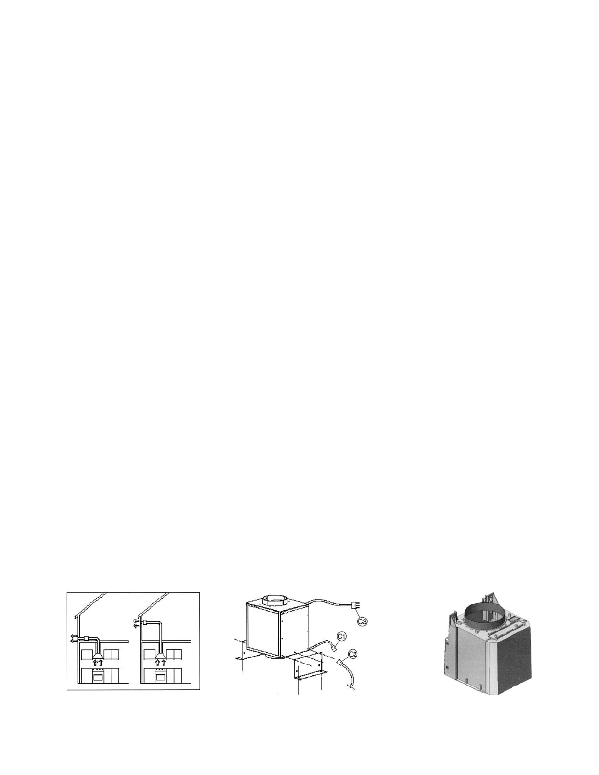
INSTALLING THE REMOTE UNIT:
The equipment can be wall-mounted, ceiling-mounted, or floor-mounted, horizontally or vertically (Figure 1).
1.) After having decided where and how the equipment is going to be installed, secure the brackets (provided) with the screws (provided).
2.) Place the equipment exactly where it is going to be installed. Mark the location of the holes on the wall. Drill the holes and insert the screw anchors
provided. The diameter of the holes must be suitable for the diameter of the screw anchors (see Figure 2).
3.) Align the holes of the brackets with the holes of the screw anchors, and screw in the screws.
4.) Make sure that the anchoring points are able to bear the weight of the equipment.
5.) Install (using 4 screws supplied) the provided pipe fitting (see Figure 3) above the hood motor in order to connect the fume outlet pipe of the hood
to the external extraction unit.
A. Do not use pipes with diameter smaller than 150 millimeters (6 inches), avoid using angled or flexible pipes, make sure that the pipes are
at least of the minimum length.
B. Make sure that the direction of the air inlet and outlet is as indicated on the arrow on the equipment label.
C. The equipment must be used exclusively with the 4-speed electronic control panel installed on the hood.
6.) Connect the 6-pole connector C1 of the equipment to connector C2 of the electronic control panel of the hood. First, make sure that the conveyor
that is normally installed on the hood has been removed and disconnected from the power supply line and from the 4-speed electronic control panel.
7.) Connect the appliance to the power supply in compliance with the relevant regulations.
Futuro Futuro
Remote Blower Kit
Installation Instructions
6-pole
connectors
(control panel)
Power supply
Figure 1 Figure 2 Figure 3

REMOVING BLOWER MOTOR FROM RANGE HOOD
STEP 1
STEP 2
STEP 3
STEP 4