092514-JA www.elitescreens.com 1
VMAX Dual Series
Dual Format Electric Projection Screen
User’s Guide
Important Safety and Warning Precautions
Make sure to read this user’s guide and follow the procedures below.
Caution: The screen’s Black Top Drop is already set to its maximum drop distance. There is NO extra Black Top
Drop in the roller. Please be aware of this as it will void your warranty with Elite Screens. Unapproved changes or
modifications (except for cutting the power cord for hardwire installations) to this unit are prohibited and will void
your warranty. For more information, please contact our Technical Support Dept. at (877) 511-1211 Ext. 604.
Please retain this user’s guide for future reference.
To avoid damaging the unit, do not use with any unauthorized accessories not recommended by the
manufacturer.
Handle the unit carefully during transportation to avoid any damages.
To ensure safe and reliable operation, direct connection to a properly grounded power source is
advised.
The power outlet supplying power to the unit should be close to the unit and easily accessible.
Do not install the unit on uneven or inclined surfaces.
Do not put heavy objects on the power cord and position it properly to avoid creating a trip
obstacle.
Never overload the power cord to prevent an electric shock or fire due to a loose contact or a short
circuit.
There are not user serviceable parts in this unit. Do not attempt to disassemble this unit by yourself.
No one except authorized technicians can open and make repairs to this unit.
Make sure the power source this unit is connected to has a continuous power flow.
If there is need to use an extension cord, make sure the cord has an equal rating as the appliance to
avoid overheat.
Do not handle the power plug when your hands are wet or your feet are in contact with water.
Do not use this unit under the following circumstances.
Disconnect the power cord under the conditions of heavy rain, wind, thunder or lightning.
Avoid direct Sunshine, rain shower and moisture.
Keep away from fire sources and high temperature to prevent this device from overheating.
Cut off the power supply first before transportation or maintenance.
Fully disconnect from the power supply when the unit is not in use for a long period of time, as
should be done with any other electric household appliance.
To avoid possible injury and/or an electric shock, do not attempt to use the screen if there is
obvious damage or if there are any evident broken parts.
092514-JA www.elitescreens.com 2
Pre-Installation
1. Carefully unpack the screen.
2. Always handle the screen in a leveled position on a clean surface.
3. In order to protect the screen from exposure to stains, keep the screen out of contact with foreign
particles such as dust, sawdust, and/or liquids.
Installation Warning
Due to various installation environments, the instructions provided in this user’s guide are for reference
only. Please consult a professional installation company for further installation and safety advice. The
installer must insure that proper mounting hardware is used to provide adequate strength suitable for the
installation. Elite Screens is not liable for any faulty installations.
Individual modifications to this product are prohibited and will void the warranty with the manufacturer. Please
contact Elite Screens Customer Service for any questions.
These limits are designed to provide reasonable protection against harmful interference in a residential
installation. This equipment generates and can radiate radio frequency energy and, if not installed and used
in accordance with the instructions, may cause harmful interference to radio communications.
However, there is no guarantee that the interference will not occur on a particular installation. If this
equipment causes harmful interference to radio or television reception, which can be determined by turning
the equipment off and on, the user is encouraged to try to correct the interference by one or more of the
following measures.
Reorient or relocate the receiving antenna of the device which may be casing the interference.
Increase the separation between the screen and the device’s receiver.
Connect the equipment into a different power outlet other than the device.
Note
Regardless of the mounting method, the screen should be securely supported so that the vibration or
pulling on the viewing surface will not cause the casing to become loose or fall. The installer must insure
that the fasteners used are of adequate strength and suitable for the installation location.
Hardware Parts List for the VMAX Dual Series
Please make sure all of the following items are included before proceeding with installation.
A. Hollow Wall Anchor x 6 pcs
B. Screw x 6 pcs
C. R18mmx6mm Washer x 6 pcs
D. M6x12mmx1.5mm washer,
M6x24mm screw, M6 nut x 4 pcs
F. Black Tape x 2 pcs
092514-JA www.elitescreens.com 3
Weight Bar Notice and Black Tape
The VMAX Dual’s weight bars have been secured to hold in place with a metal plate which is screwed on.
Please remove the metal plate prior to operating the screen. The screen will not deploy while the metal
plate is in place. Failure to remove the metal plate will result in possibly damaging the motor.
Weight bar metal plate removal
1. Unscrew both screws from the concave metal plate and remove it from the weight bars.
Black Tape
2. Stick a strip of black tape (F) over the two screw holes under the weight bar to cover them.
The screw holes under
the weight bars.
Concave metal plate
F. Black Tape
092514-JA www.elitescreens.com 4
Installation
The VMAX Dual Series screen is designed for installation on a wall or ceiling. All hardware is included to
allow a wall installation. A professional installer is strongly recommended for safety purposes.
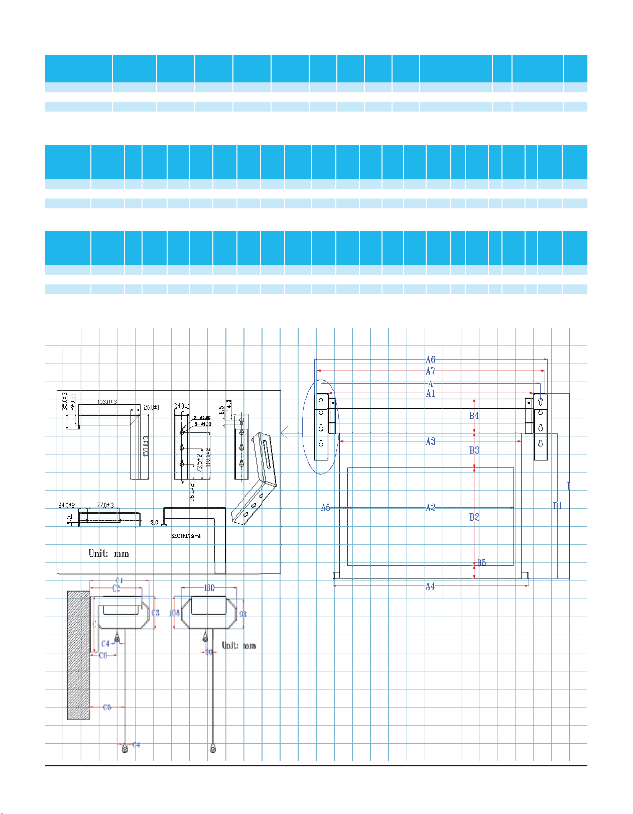
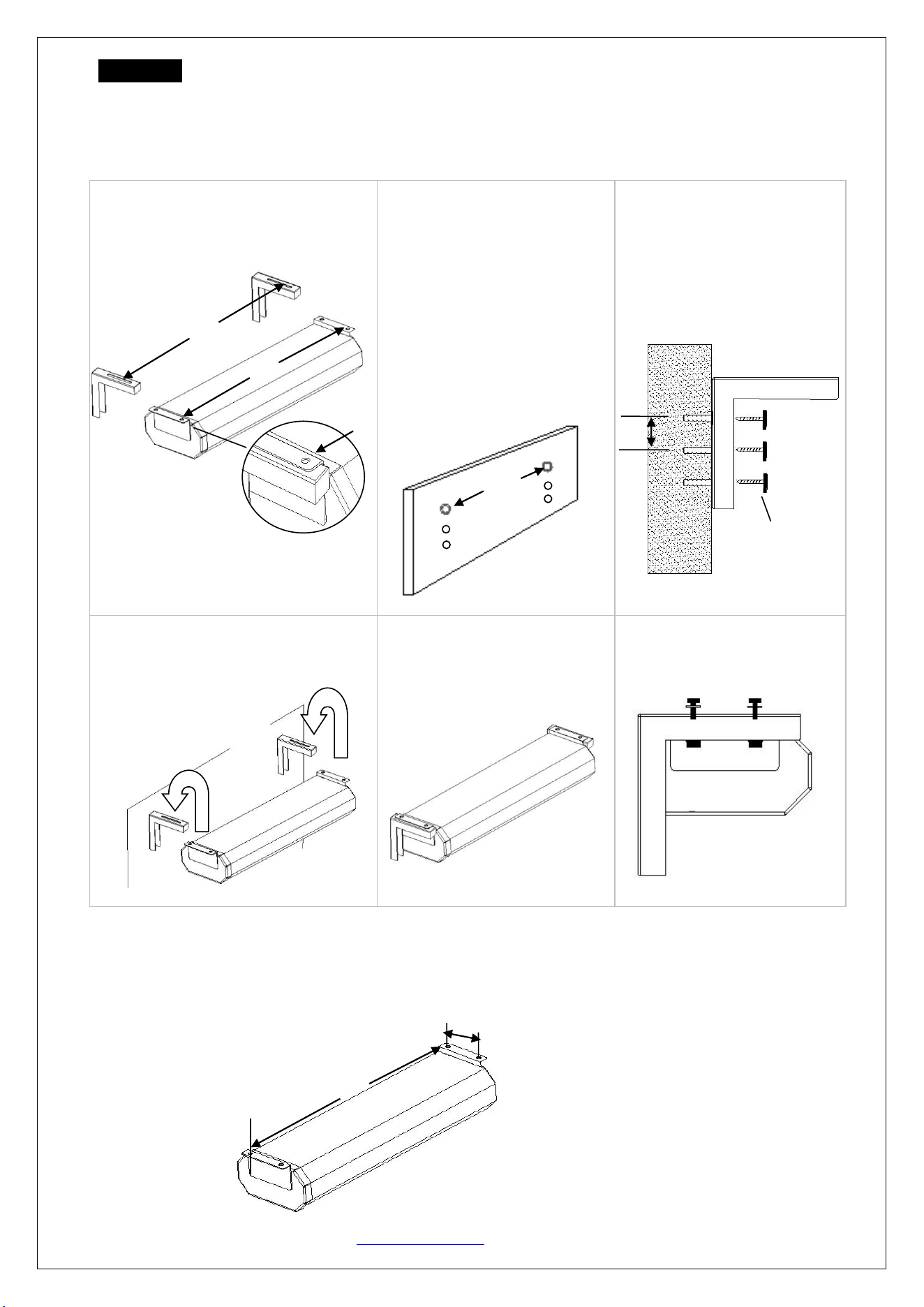
A. Wall Installation
1. Measure the length distance (L)
between each hole on the screen’s end
flange as shown in the image above.
2. Measure and mark the
required height for your
installation. Next, drill three
holes vertically 37mm apart for
the 6 inch wall brackets (E).
Then, drill another hole
according to the measurement
distance obtained from Step 1.
Finally, drill the remaining two
holes for the wall bracket.
3. Insert the hollow wall
Anchors (A) into the drilled
holes. Align the 6 inch wall
brackets (E) to the drilled
holes and secure with the
screws (B).
4. After securing the 6 inch wall
brackets (E)to the wall, bring the
screen over the top of the brackets.
5. Align the screw holes from
the screen’s end flanges to the
wall brackets top opening.
6. Insert the M6x24mm screw
& washer and secure with the
M6 nut (D).
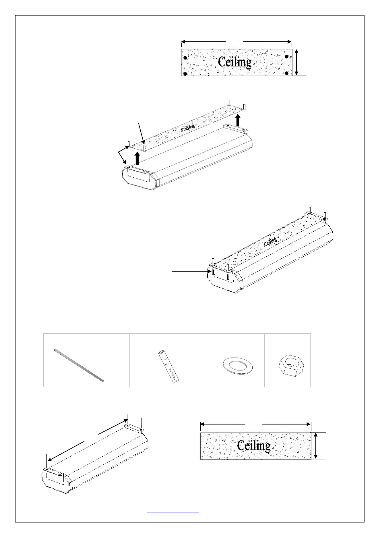
B. Ceiling Installation
1. Measure the (L) and (W) distance and mark the area on your ceiling. Those measurements are the holes
located at the end flanges of the VMAX Dual screen as shown in the drawing.
WALL
L
WALL
L
L
WALL
Woodscrew and
R18mmx6mm
washer
37mm
L
W
Two or more people are
required to lift screen up.
092514-JA www.elitescreens.com 5
2. Drill four holes in the ceiling and insert the hollow wall anchors (A) in each of the drilled holes.
Two or more people are required for the next steps
3. Carefully bring up the screen and align the end flange holes of the screen with the two drilled holes in the
ceiling.
4. Insert the screw (B) in the hollow wall anchor (A) and fasten with a screw (B) to secure the screen in
place. Repeat procedure until screen is safely installed.
C. Suspended (Optional Ceiling Installation)
The following list of hardware is not included with the VMAX Dual. These are general hardware parts
required for installing the VMAX Dual on a high ceiling.
F. Threaded Screw Rod x 4
G. Expansion anchor x 4
H. Washer x 12
I. Nut x 12
1. Measure the (L) and (W) distance and mark the area on your ceiling. Those measurements are the holes
located at the end flanges of the VMAX Dual screen as shown in the drawing.
Hollow Wall
Anchor
Align the
holes
W
L
Screw (B) is inserted
into hollow anchor (A).
L
W
L
W
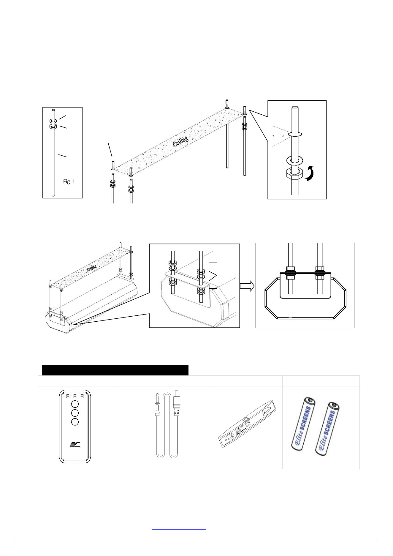
092514-JA www.elitescreens.com 6
2. Insert the nuts (I) and washers (H) into every threaded screw rod (F) as shown on Fig 1.
3. Next, insert the expansion anchors (G) in the four drilled holes and put the threaded screw rod in the
expansion anchors (Fig 2).
4. Then fasten the nuts (I) to secure the position of the threaded screw rod (Fig.3).
5. Lastly, align the end flange holes to the threaded support rods and fasten them with the nuts and washers
as show below.
Accessories for the VMAX Dual Series
RF remote x 1
5-12V trigger cable x 1
Bubble leveler
AAA batteries x 2
Fig.1
G
Fig.2
Fig.3
H
I
F
H
I
I
092514-JA www.elitescreens.com 7
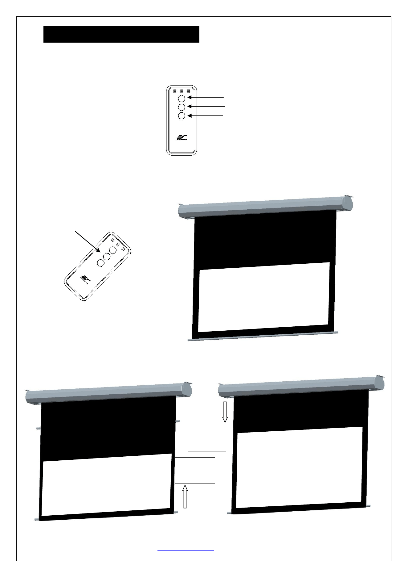
Control System and Screen Operation
The VMAX Dual series screen’s main unique feature is the ability of changing the screen’s ratio to
2.35:1and 16:9 with the push of a button with the RF remote (Radio Frequency). This is accomplished by
the screen’s dual screen materials and motors.
1. Radio Frequency Remote Operation
Press the 2.35:1 button on the RF remote so the screen can lower and display a 2.35:1 format.
Press the 16:9 button on the RF remote, this will retract the 2.35:1 screen into the housing. When the 2.35:1
screen has stopped, the 16:9 screen commences its deployment.
2.35:1
UP
16:9
2.35:1
2.35:1 screen
retracts
16:9 screen
deploys
092514-JA www.elitescreens.com 8
Press “UP” button on the RF remote to retract the screen into the housing.
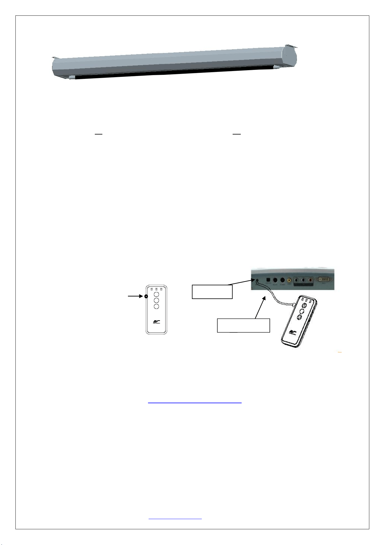
2. Wireless 5-12 volt trigger operation
The VMAX Dual may be controlled through a projector’s 5-12 volt trigger through the Radio Frequency
remote control. It will synchronize with the projector’s power cycle and deploy the16:9 screen when the
projector is turned on and retract it when the projector is powered off.
Plug the 5-12 volt trigger cable as shown below and turn on your projector.
If the 16:9 screen does not deploy, try the following steps to reprogram the RF remote to your VMAX Dual.
Step1: Make sure to unplug your screen from the power outlet
Step2: Hold the UP button on your RF remote
Step3: While holding the UP button, plug the screen back to the power outlet
Step 4: Wait 5 seconds and then release the UP button
Step 5: The RF remote should now be programmed with your screen and ready to synchronize with your projector’s
power cycle
Repeat the steps again if unsuccessful.
Note: The projector’s on/off cycle may take longer to fully activate. It typically takes anywhere from 20-30
seconds for full off/on cycle to function each time.
For a local Elite Screens contact or technical support, please visit
www.elitescreens.com
DC 5-12V OUT
12V wireless trigger
Example of the back ofthe projector
5-12 v input port
