Futuro Futuro
Futuro Futuro
www.FuturoFuturo.com
Technical Support:
1-718-236-1570 ext. 111
Installation Instructions
JUPITER
wall-mount model
MOUNTING INSTRUCTIONS FOR “JUPITER” HOOD - WALL VERSION
ISTRUZIONI MONTAGGIO CAPPA «JUPITER» - VERSIONE PARETE
Pg: 1/2 • Ver: 1.9 • Lang: IT/EN
ENGLISH
:
Phase 1:
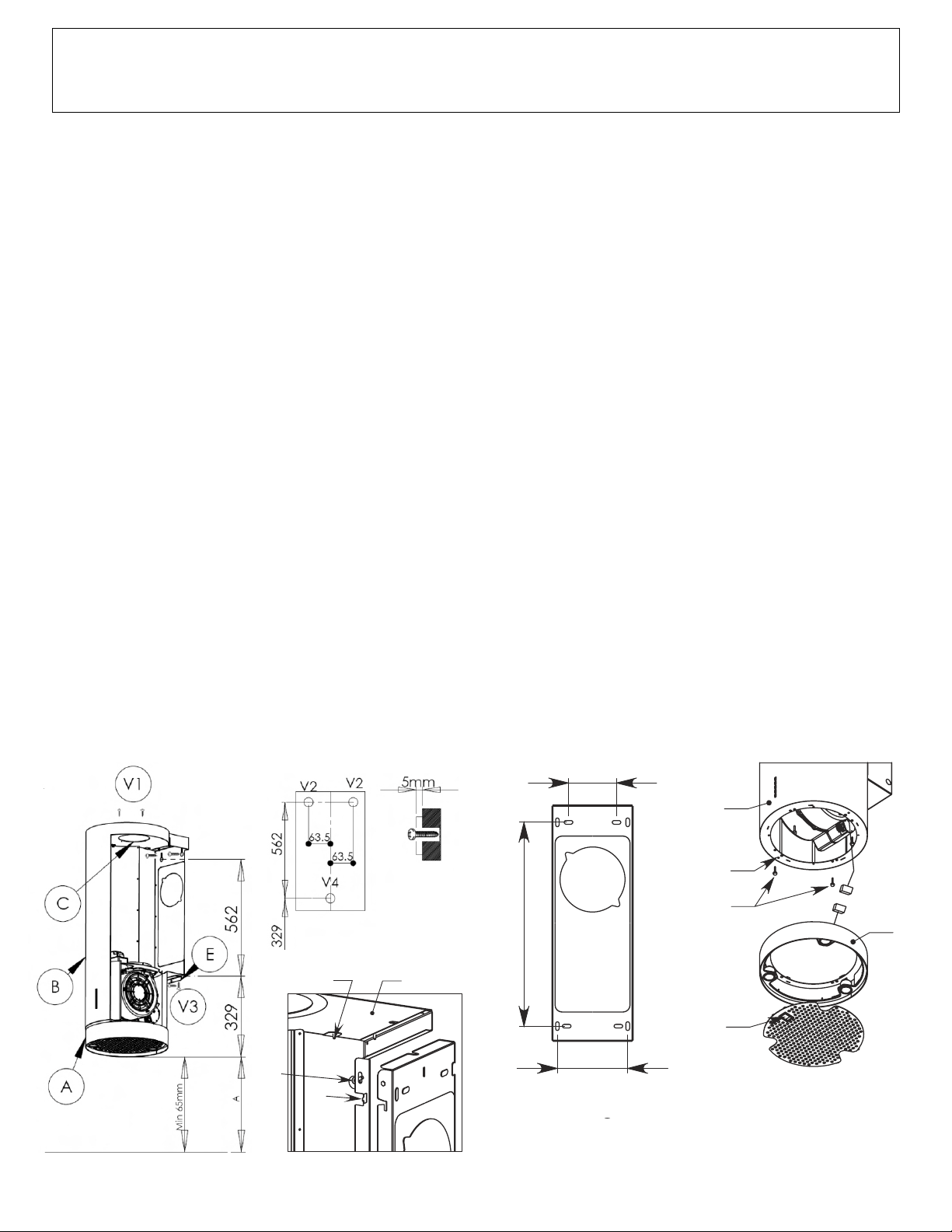
1.) Identify the desired distance (A) between the hood and the cooking surface (Fig.1) - recommended is 26” to 30”.
2.) Remove the screws (V1) and remove the top (C).
3.) Mark the holes V2 and V4, following the dimensions of the drawing (see Fig. 2).
4.) Using a level, check that the 2 holes V2 are horizontal.
5.) For installation into wood beams / joists: drill the holes and screw in the wall attachment screws, leaving approximately 5 mm spacing
between the bottom of the screw head and the wall.
5a.) For installation into concrete / masonry: drill the holes, install the supplied expansion plugs (8mm diameter), then screw in the wall
attachment screws, leaving approximately 5 mm spacing between the bottom of the screw head and the wall.
6.) Attach the security bracket (E) to the wall, as shown in Fig.1.
Phase 2:
1.) Align the holes on the back of the hood with the screws on the wall. Check that the screws are securely seated.
2.) Attach the hood to the wall and screw in the fixing screws.
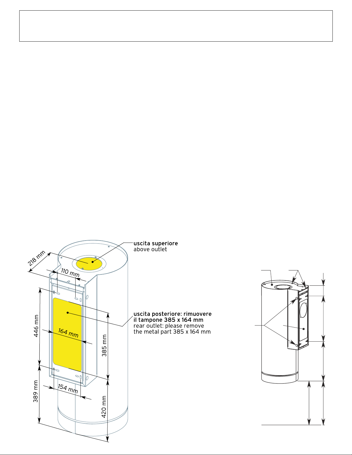
3.) Ducted installation: attach the duct to the blower output. (Ductless installation: skip this step.)
4.) Disconnect power supply (circuit breaker), then connect the hood's electrical system.
5.) Put the cover back in place and screw it in with the corresponding screws (V1).
6.) Attach the bottom section of the spacer onto the bracket (E) using the metric screws V3.
(Optional) Glass Panel Installation:
1.) Remove the metal filter using the corresponding handle (M).
2.) Disconnect the connector (S) of the light fixture cable.
3.) Unscrew the 4 knurled metric screws M4 (V4), then remove the lower ring section (A) from the hood body.
4.) Slightly unscrew the two centering / anti-rotation metric screws (V5) in the bottom flange of the hood body (B).
5.) Center the holes of the glass panel with the metric screws.
6.) Re-attach the lower ring section (A) to the body (B) with the 4 knurled metric screws M4.
7.) Re-connect the halogen light connector (S).
8.) Replace the metal filter.
Fig. P2
446
105 mm
154 mm
F1
F2
V4
V3
B
V2
Fig. P4
F
C
E
V6
D
V5
Fig. 2
Fig. 1
Futuro Futuro
Futuro Futuro
www.FuturoFuturo.com
Technical Support:
1-718-236-1570 ext. 111
Installation Instructions
JUPITER
wall-mount model
MOUNTING INSTRUCTIONS FOR “JUPITER” HOOD - WALL VERSION
ISTRUZIONI MONTAGGIO CAPPA «JUPITER» - VERSIONE PARETE
Pg: 1/2 • Ver: 1.9 • Lang: IT/EN
446 mm
93
8
m
m
6
0
6
0
m
6
-
7
m
H1
5
9
m
m
A
V1
V4
B
Fase 1
1) Individuare l’altezza (H1) desiderata tra cappa e piano cottura (Fig. P1).
2) Rimuovere la schiena (A) togliendo i tappi di copertura (V1) e agendo sulle relative viti di fissaggio interne (V2).
3) Segnare i 4 punti di foratura F1 e F2 seguendo le quote indicate in Fig. P1 e Fig. P2 o utilizzando la schiena come dima di foratura.
4) Forare, inserire i tasselli ad espansione Ø8mm, e fissare la schiena a parete tramite le relative viti da muro.
5) Controllare con bolla di livello l’allineamento orizzontale e verticale della schiena.
Fase 2
1) Agganciare la cappa alla schiena tramite i 4 ganci (V3), assicurandosi che la cappa scenda di circa 1cm e verificandone la tenuta
(Fig. P3).
2) Avvitare le due viti di fissaggio superiori (V2) senza bloccarle completamente.
3) Alzare la cappa nella posizione desiderata e avvitare definitivamente le viti di fissaggio (V2) inferiori e superiori.
4) Nel caso di versione aspirante individuare la lunghezza ottimale del tubo di scarico dei fumi ed eseguire il collegamento: quando
possibile il coperchio (B) può venir temporaneamente rimosso agendo sulle relative viti di fissaggio (V4).
5) Eseguire il collegamento elettrico solo dopo aver disinserito l’alimentazione elettrica.
MONTAGGIO CAPPA CON VETRO
1) Rimuovere il filtro metallico agendo sulla maniglietta (C).
2) Disconnettere il connettore (D) del cavo dei faretti.
3) Rimuovere il corpo (E) dal cono (F) svitando le 4 viti metriche M4 zigrinate (V5).
4) Svitare leggermente le 2 viti metriche di centratura e di antirotazione (V6) presenti nella flangia inferiore del cono (F); centrare le
asole del vetro con le viti metriche.
5) Agganciare il corpo (E) al cono (F) con le 4 viti metriche M4 zigrinate.
6) Riconnettere il connettore (D).
7) Riagganciare il filtro metallico agendo sulla maniglietta (C) - Fig. P4.