Installation
Instructions
For Wine Cooler
WUgb 3400
7080 200-02
2
Please Read and Follow these
Instructions
These instructions contain Danger, Warning and
Caution notes.
This information is important for safe and efficient
installation and operation.
Always read and comply with all Danger, Warning and
Caution notes!
DANGER!
Danger indicates a hazard which
will cause serious injury or death if
precautions are not followed.
WARNING!
Warning indicates a potentially hazardous
situation which, if not avoided, could
result in death or serious injury.
CAUTION!
Caution indicates a potentially hazardous
situation which, if not avoided, may result
in minor or moderate injury.
IMPORTANT
This indicates information that is especially relevant
to a problem-free installation and operation.
T
able
of
C
onTenTs
Note to the Installer
It is very important to follow the instructions in the
manual to ensure proper installation and operation of
the cabinet.
Before installing the unit, be sure to thoroughly read
and understand all of the information in this manual.
Table of Contents Page
Please Read and Follow these Instructions...................2
Note to the Installer .........................................................2
R600a Refrigerant ..........................................................2
Disposal of Old Appliance ..............................................3
Important Safety Information ..........................................3
Disposal of Carton ..........................................................3
Electrical Safety ..............................................................3
Supplied Accessories .....................................................4
Air Flow in the Appliance Base ......................................5
Dimensions of Appliance Door .......................................5
Appliance Dimensions ....................................................6
Installation Dimensions ...................................................6
Angle Bracket for Cover Panel .......................................7
Mounting the Dust Filter .................................................8
Appliance Venting ...........................................................8
Installing the Appliance...................................................9
Changing Over Door Hinges ........................................12
R600a Refrigerant
WARNING!
The refrigerant R600a contained within the
appliance is environmentally friendly, but
flammable. Leaking refrigerant can ignite.
To prevent possible ignition,
follow the warnings below:
•
Keep ventilation openings, in
the appliance enclosure or in
the built-in structure, clear of
obstruction.
• Donotdamagetherefrigerantcircuit.
• Anyrepairsandworkontheappliance
should only be performed by the customer
service department.
Blocking for Safety
WARNING!
To avoid a hazard due to instability of the
appliance, it must be fixed in accordance
with the instructions.
3
s
afeTy
Important Safety Information
• Topreventinjurytoyouordamagetotheunit,the
appliance should be unpacked and set up by two
people.
• Iftheapplianceisdamagedondelivery,contact
the supplier immediately before connecting it to the
power source.
• Toguaranteesafeoperation,ensurethatthe
appliance is set up and connected as described in
this manual.
• Whendisconnectingtheappliance,alwayspullitout
by the plug; never pull on the cord.
• Toprotecttheappliancefrompossibledamage,allow
it to stand 1/2 to 1 hour in place before turning on
the electricity. This allows the refrigerant and system
lubrication to reach equilibrium.
Disposal of Old Appliance
DANGER!
Risk of child entrapment.
Child entrapment and suffocation are not problems of
the past.
Junked or abandoned refrigerators are still dangerous –
eveniftheywillsitfor“justafewdays.”
If you are getting rid of your old refrigerator, please fol-
low these instructions to help prevent accidents.
Before you discard old appliances:
• Takeoffthedoors.
• Leavetheshelvesinplacesothatchildren
may not easily climb inside.
• Cutoffthepowercordfromthediscarded
appliance. Discard separately from the appli-
ance.
• Besuretofollowyourlocalrequirementsfor
disposal of appliances.
Contact the trash collection agency in
your area for additional information.
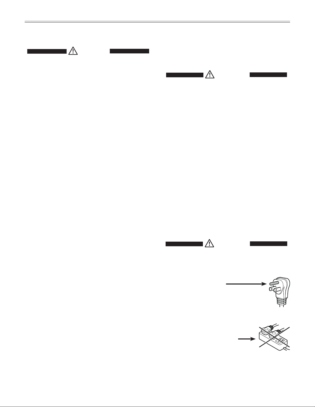
Electrical Safety
Connect this appliance to a 15 amp or 20 amp, 110-
120 VAC, circuit which is grounded and protected by a
circuit breaker or fuse.
We recommend using a dedicated circuit for this appli-
ance to prevent circuit overload and the chance of
interruption to the appliance.
This appliance is equipped with a three-prong (ground-
ing) polarized plug for your protection against possible
shock hazards.
Where a two-prong wall receptacle is encountered,
contact a qualified electrician and have it replaced with
a properly grounded three-prong receptacle in accor-
dance with all local codes and ordinances.
WARNING!
Electrocution hazard.
Electricalgroundingrequired.
•
Do not remove the round grounding
prong from the plug.
•
Do not use extension cords or
ungrounded (two-prong) adapters.
• Donotuseapowercordthatisfrayedor
damaged.
•
Do not use a power strip.
Failure to follow these instructions may
result in fire, electric shock or death.
Disposal of Carton
The packaging is designed to protect the appliance and
individual components during transport and is made of
recyclable materials.
WARNING!
Keep packaging materials away from
children. Polythene sheets and bags can
cause suffocation!
If possible, please recycle packaging material at a recy-
cling facility.
4
U
npaCking
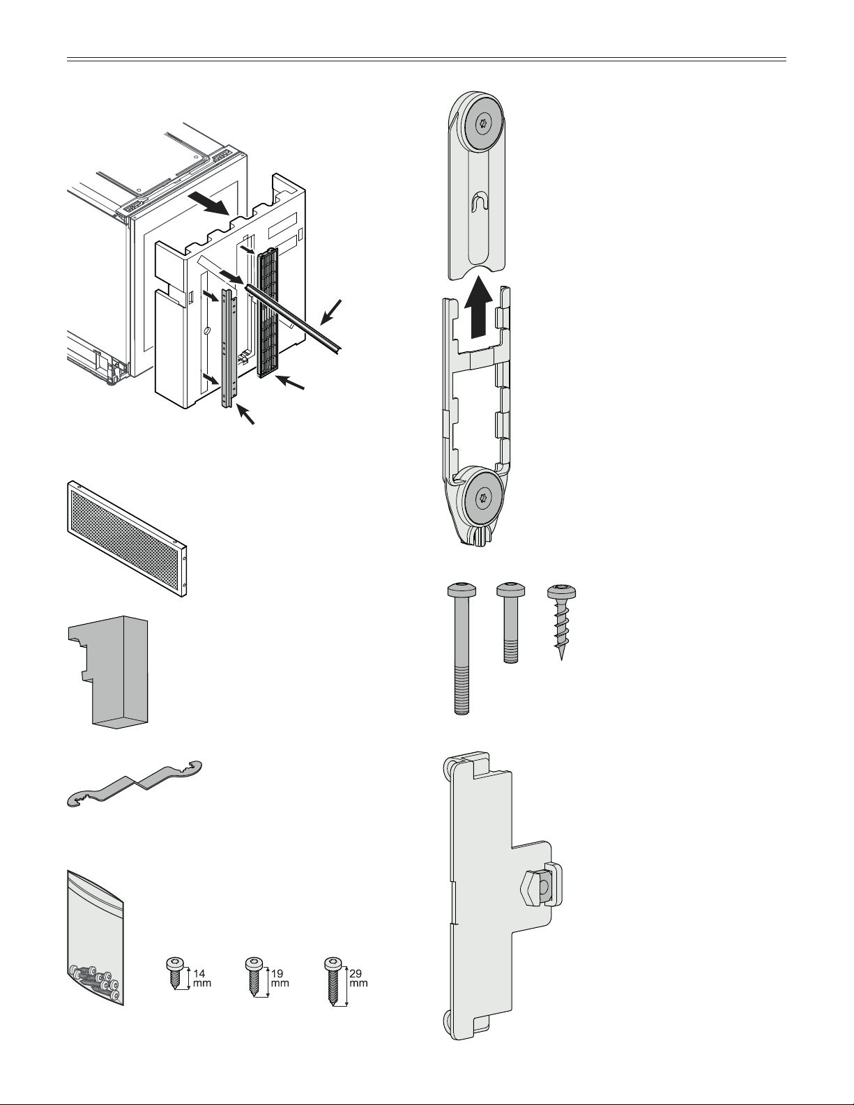
Supplied Accessories
Toe kick panel
Cover strips
Retaining screws for installation
Wrenchtoadjusttheheightoftheappli-
ance
Foam block for ventilation duct in appli-
ance base
Dust filter
Angle bracket
(for mounting a cover panel on the
top or bottom of the appliance)
4 x 14
4 x 19
4 x 29
3 pcs. 2 pcs. 3 pcs.
Magnet bracket
Base bracket
Screws for toe kick panel
assembly
3.7 x 17
4 pcs.
4 x 20
4 pcs.
4 x 35
4 pcs.
2 pcs.
2 pcs.
2 pcs.
5
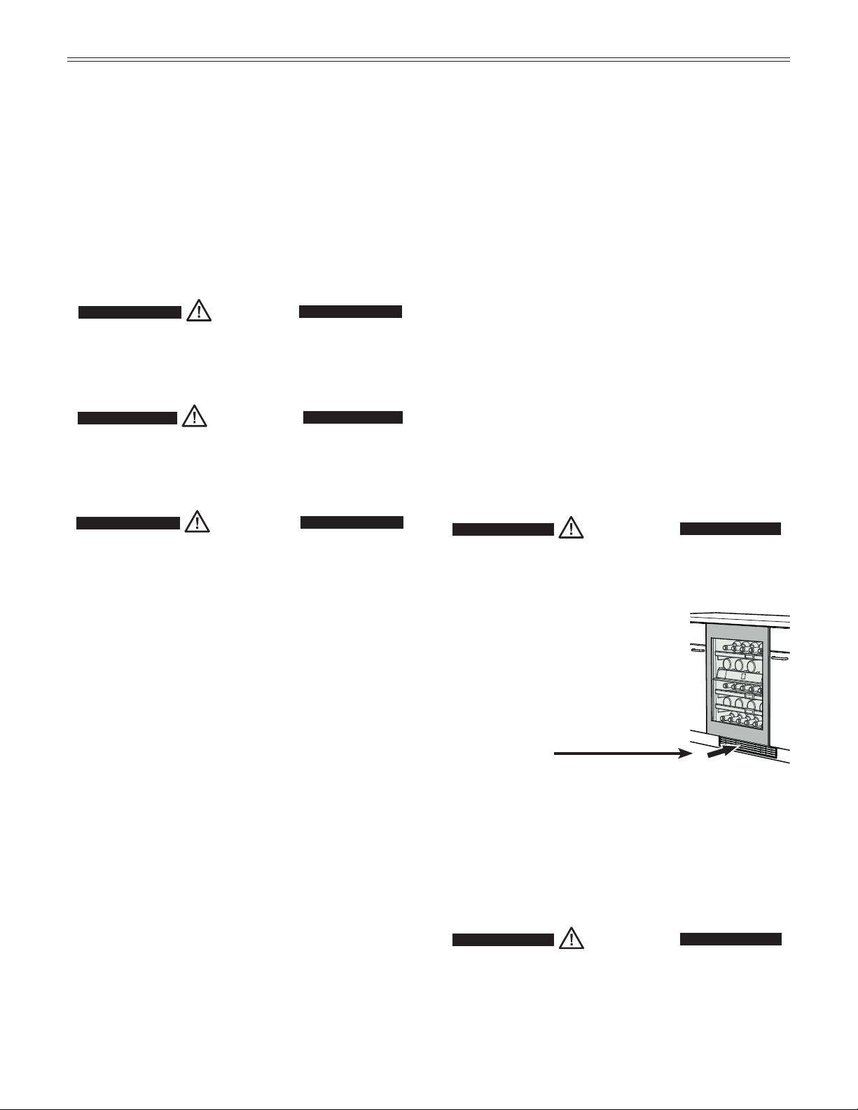
IMPORTANT
To ensure proper refrigeration performance
of the appliance, the toe
kick panel supplied must be
installed.
The foam block
supplied must be
installed in order to
ensure the required
air flow through the
appliance base.
Failure to follow
this instruction
may result in poor
refrigeration performance.
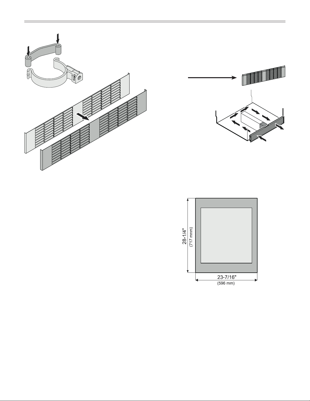
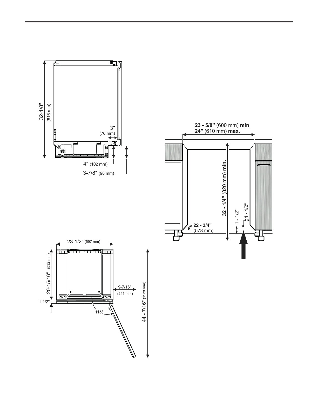
Dimensions of Appliance Door
Air Flow in the Appliance Base
p
lanning
i
nformaTion
Toe kick panel
Adjustablefeetsupport
2 pcs.
2 pcs.
6
Appliance Dimensions
Top view
Side view
Height when adjustable feet have been screwed
in as far as they will go.
Maximum height adjustment = 2" (51 mm)
to allow for a 6" (153 mm) toe kick.
Maximum door
opening angle
This is where the power cord extends from the
back of the appliance.
Free length of the power cord =
78 - 3/4 inch (2000 mm)
Be sure to take these specifications into con-
sideration when choosing the location of the
electrical outlet.
IMPORTANT
The electrical outlet must not be
situated behind the appliance and must
be easily accessible.
Installation Dimensions
IMPORTANT
In order to avoid any problems when installing the
appliance and to avoid damage to the appliance:
The floor on which the appliance stands must
be horizontal and level.
The kitchen cabinets must be aligned
horizontally and vertically.
p
lanning
i
nformaTion
7
p
lanning
i
nformaTion
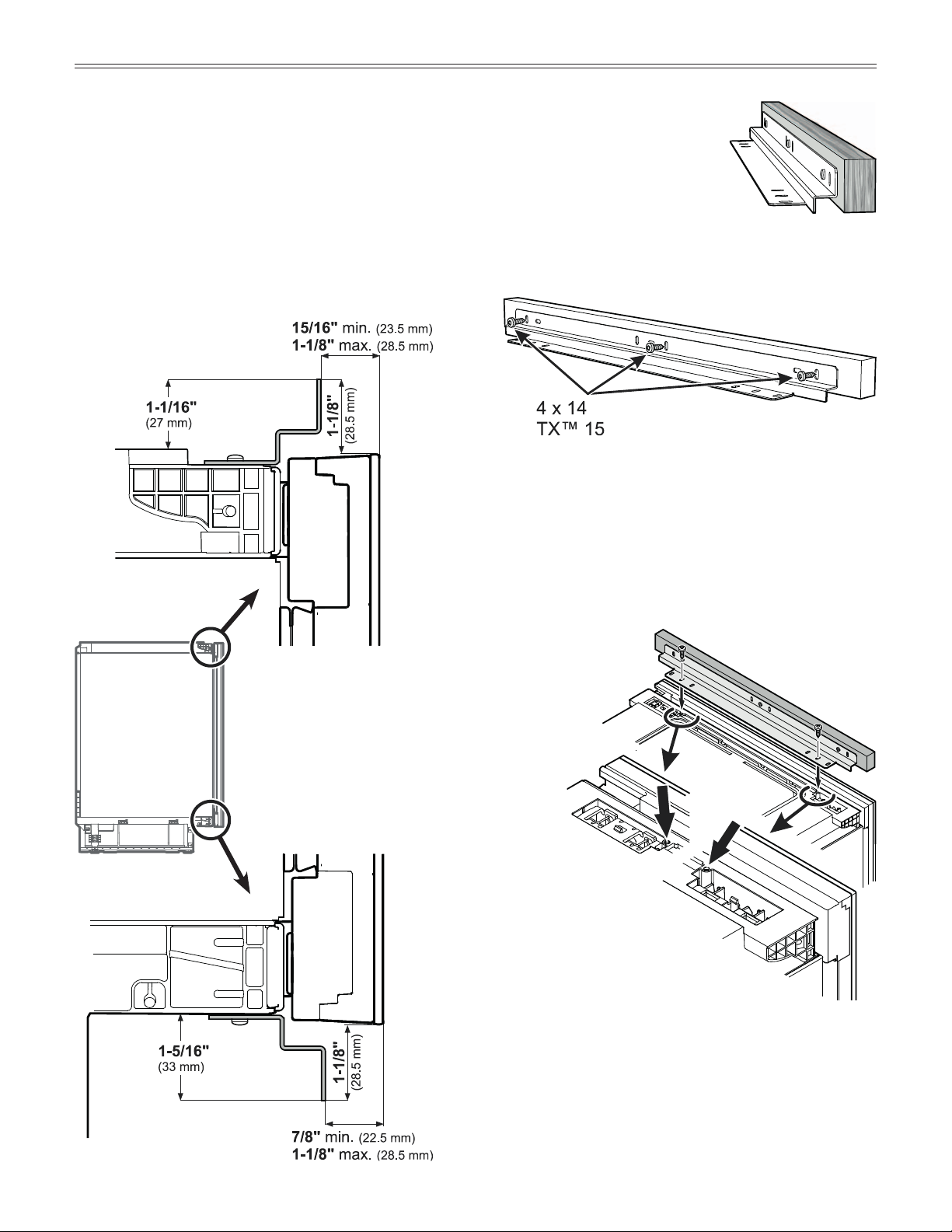
• Usetwo4x19screws.
• Screwintothedesignatedholes.
Do not tighten the screws yet.
• Adjustthebracketuntilthefrontsurfaceofthepanel
is flush with the door front.
• Finally,tightenthescrews.
Angle Bracket for Cover Panel
Depending on the height of the toe kick and the height of the counter, the supplied angle bracket
can be installed on the top or bottom of the appliance to cover unwanted openings with a panel.
The long holes in the bracket enable the bracket to slide in and out in order to align the filler
panel with the front of the door.
Dimensions of the mounted angle bracket
Mounting the premounted bracket on the
appliance top
Mounting the panel onto the angle bracket
Mount the panel onto the angle bracket using three
4 x 14 screws.
8
p
lanning
i
nformaTion
Mounting the premounted bracket on the
appliance bottom
• Usetwo4x19screws.
• Screwintothedesignated
holes. Do not tighten the
screws yet.
• Adjustthebracketuntilthe
front surface of the panel is
flush with the door front.
• Finally,tightenthescrews.
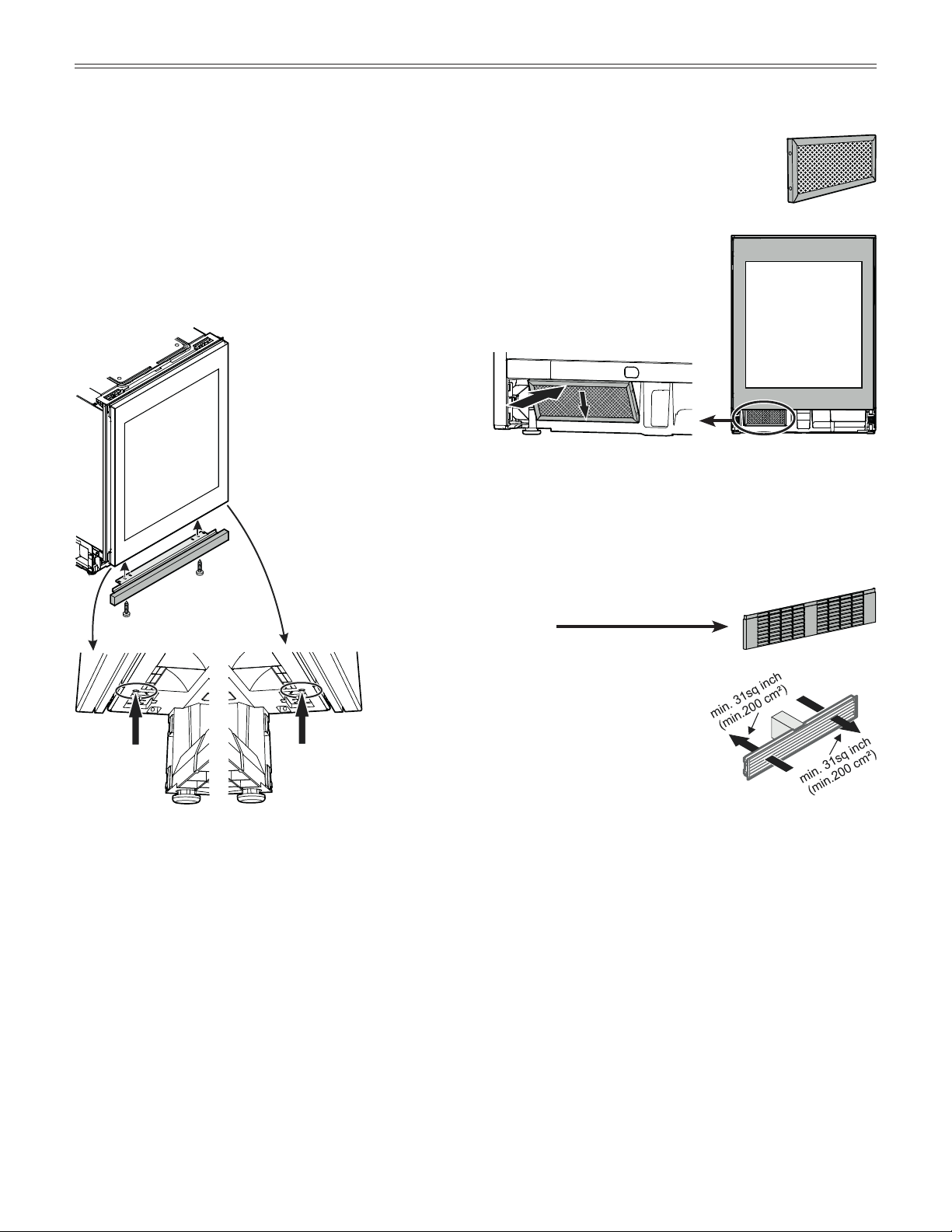
Mounting the Dust Filter
The supplied dust filter prevents dirt
from getting into the motor compartment,
which can impair the refrigeration perfor-
mance.
Therefore, always install the dust filter.
Remove the protective film from
the dust filter.
Insert the filter at the bottom and
click into place at the top.
Appliance Venting
The required air flow is directed through the toe kick
base.
It is important to use the provided
toe kick panel for the ventilation
opening.
9
i
nsTallaTion
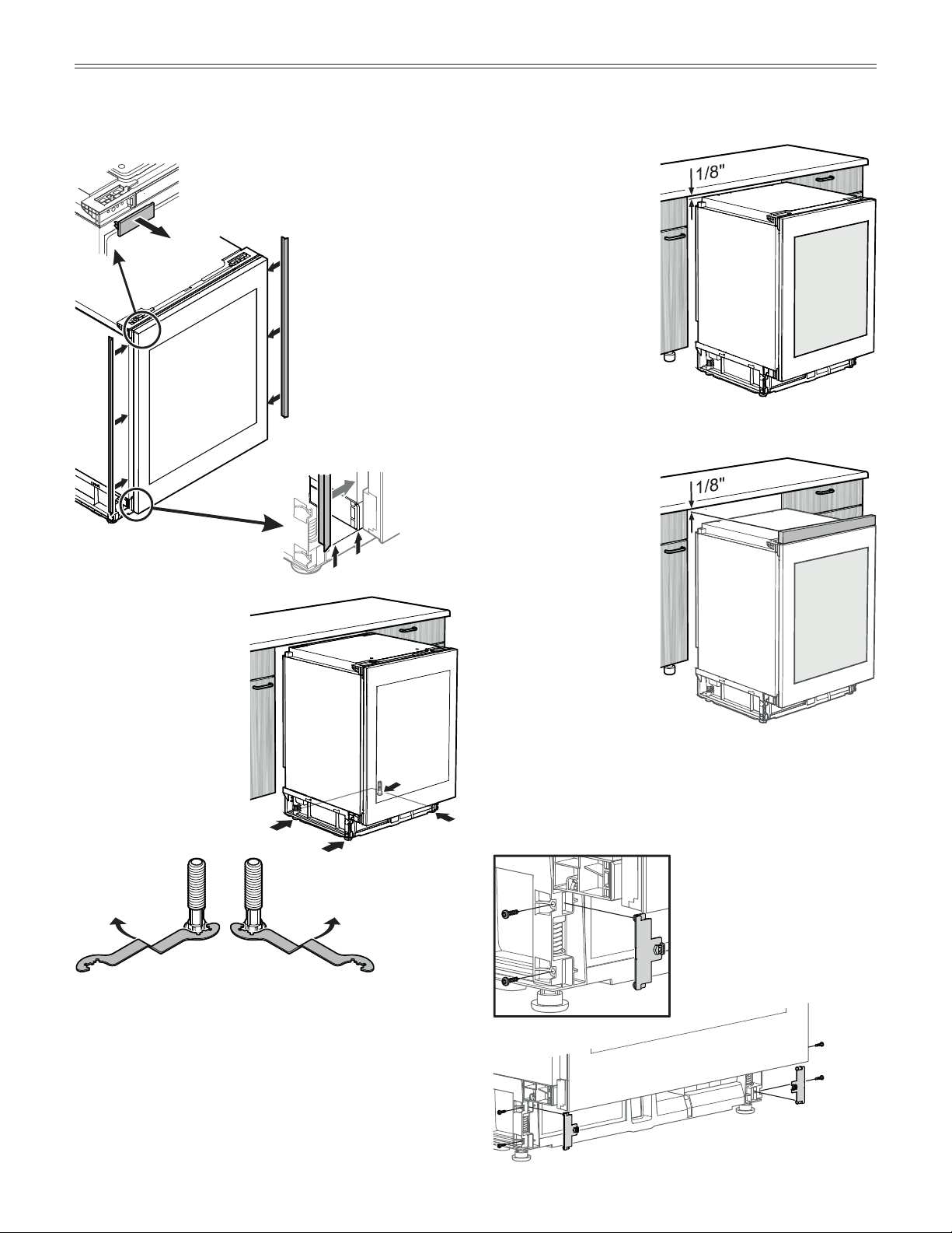
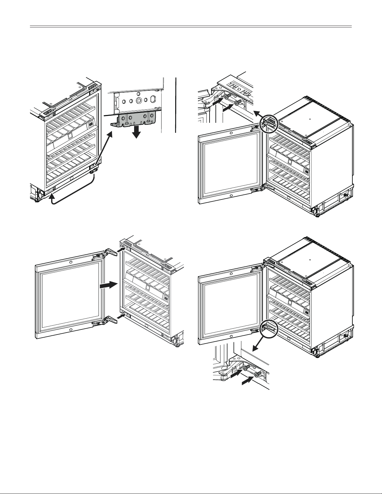
1.
Open the door and remove the top left
cover.
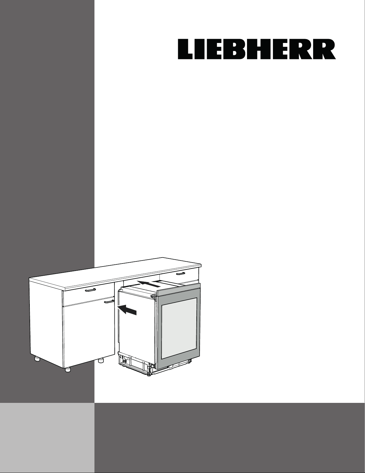
Installing the Appliance
3.
Adjusttheheightofthe
appliance by turning the
adjustablefeet.
Turn the wrench counterclockwise to raise the appli-
ance and clockwise to lower it. Position the wrench
accordingly.
IMPORTANT
The appliance must be aligned horizontally and
vertically. If the appliance is not level, the main
body of the appliance can become deformed
and the door will not close properly.
3.
2.
Apply the cover strips
to the leading edge of
the appliance housing
on the left and right.
The bottom of the strip
must be in line with
the bottom edge of
the appliance housing
(see detail below).
1.
2.
Installing version
without cover panel
on the appliance top
Adjusttheheightof
the appliance leaving
a gap of approx. 1/8"
between the appliance
top and the underside
of the countertop.
Installing version
with mounted
cover panel on the
appliance top
Adjusttheheightof
the appliance leaving
a gap of approx. 1/8"
between the top of the
cover panel and the
underside of the coun-
tertop.
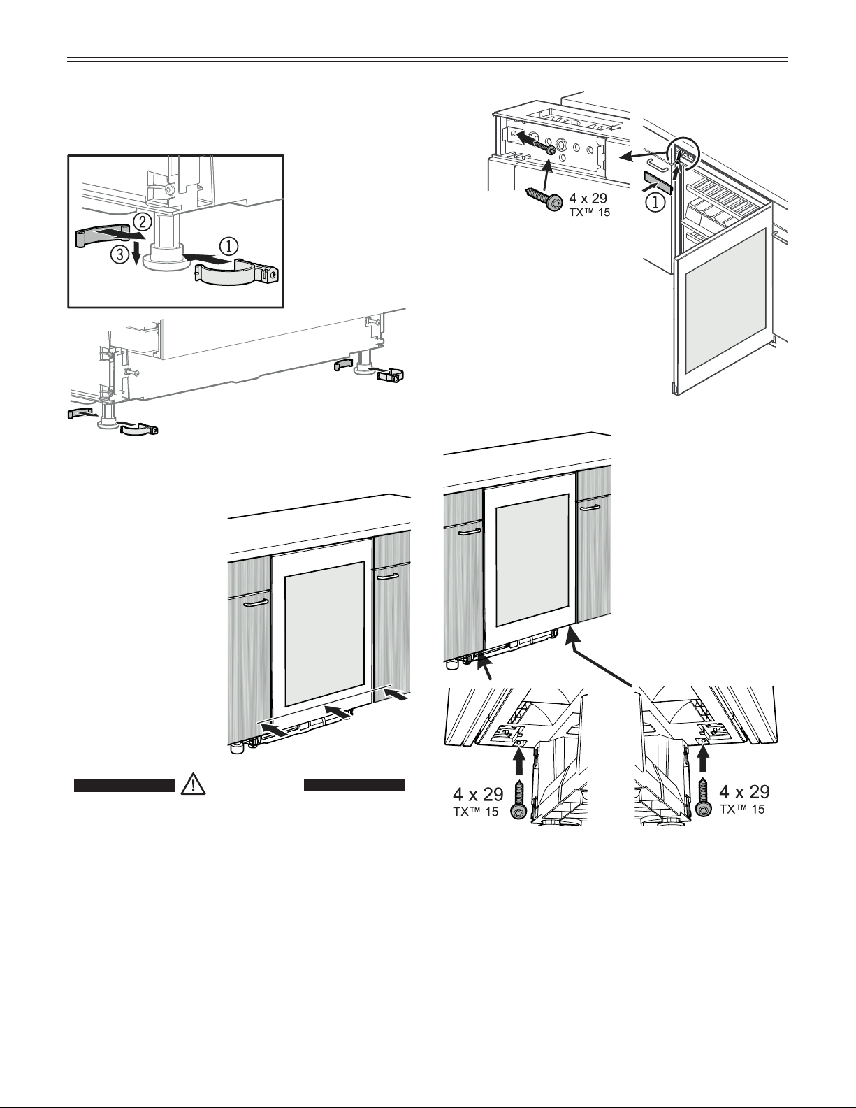
4.
Fit the base bracket.
4.
10
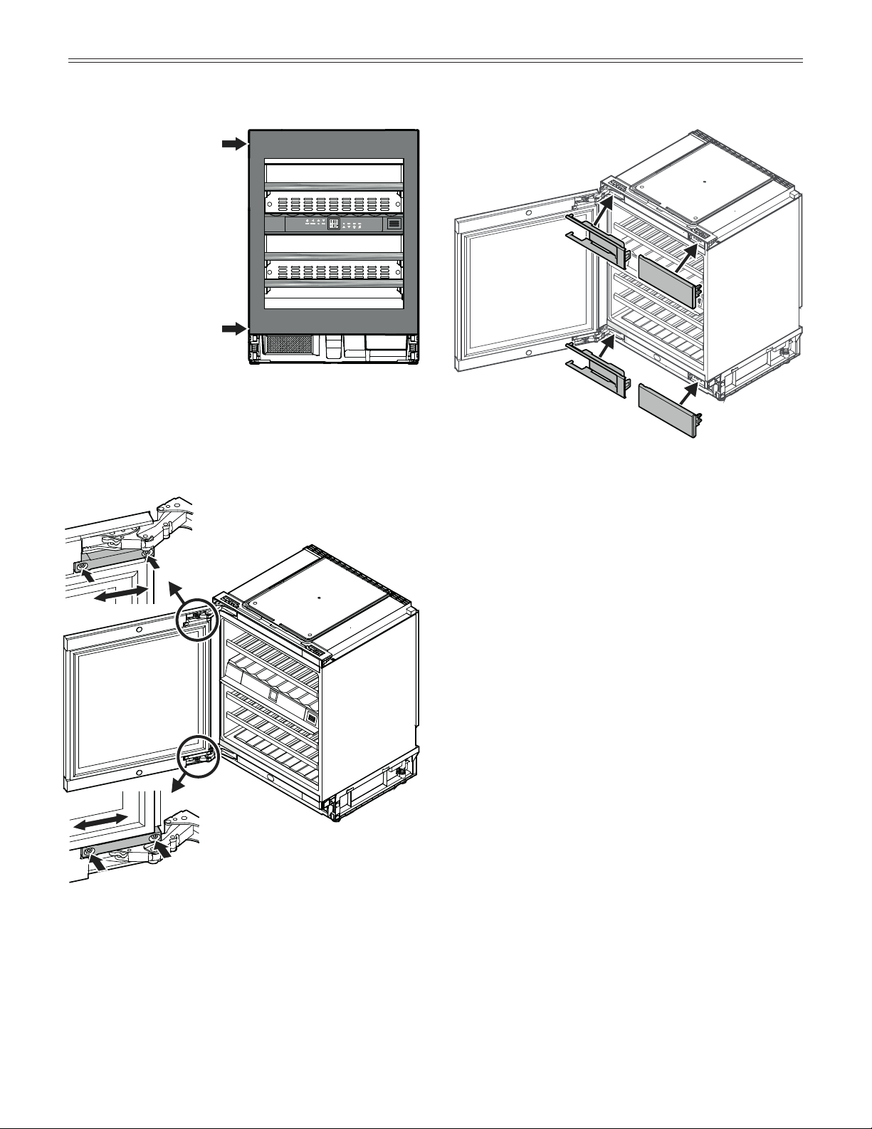
8.
i
nsTallaTion
6.
Slide in the appliance
until the front surface
of the appliance door
is flush with the cabinet
fronts.
7.
• Screwtheappliancetothe
body of the cabinet at the
top left-hand side.
• Clickcover
1 into place
again.
8.
Screw the appliance to
the body of the cabinet
at the bottom on the left
and right.
6.
7.
WARNING!
When sliding in the appliance, make sure
not to damage the power cord!
5.
Fittheadjustablefeet
support.
5.
11
1/16"
(1.4 mm)
i
nsTallaTion
Important
The foam block must be touching the toe kick
panel.
IMPORTANT
If the foam block is not installed, the
appliance will not deliver optimal refrigeration
performance during operation.
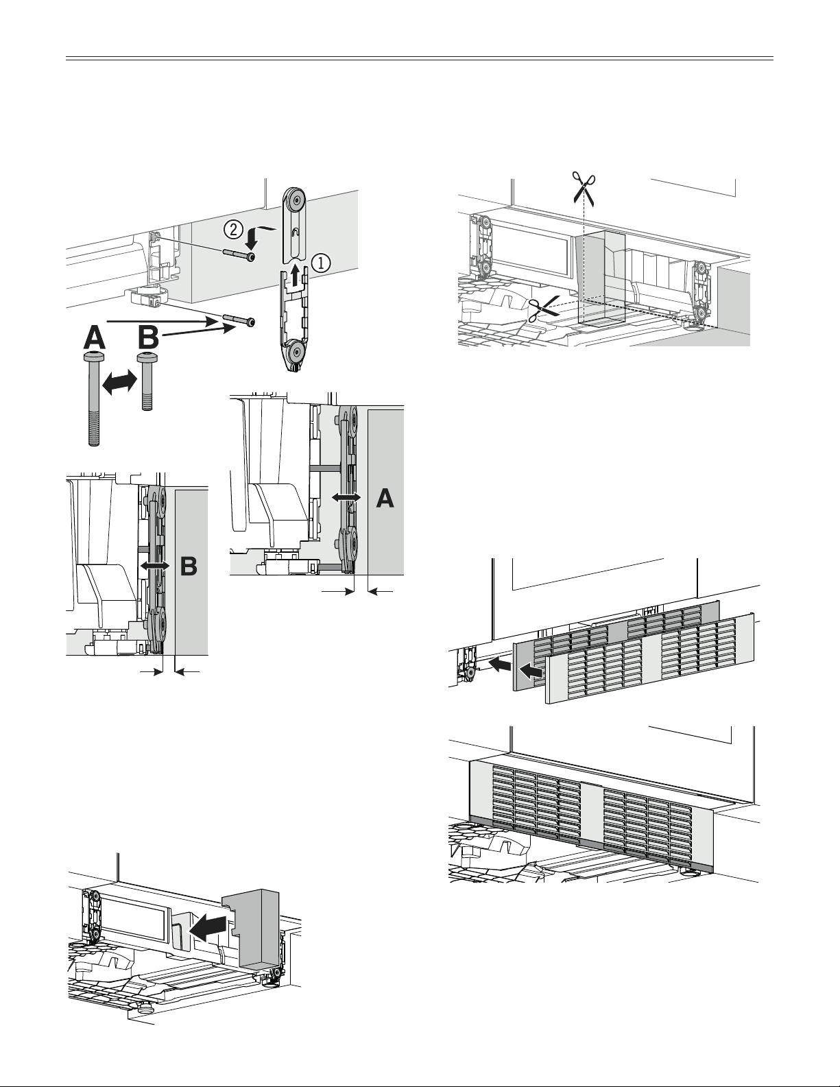
10.
9.
UsescrewA or B, depending on the position of the
baseoftheadjacentcabinet.
Fit the magnet brackets to the screw heads.
9.
11.
11.
Cut the foam block to the correct height – the depth
willdependonthepositionofthebaseoftheadjacent
cabinet.
12.
Fit the toe kick panel.
12.
1/16"
(1.4 mm)
10.
Insert the foam block into
the opening in the appli-
ance base as indicated.
12
Changing Over Door Hinges
Door hinges should only be changed by a trained
expert.
Changing over the door hinges requires two people.
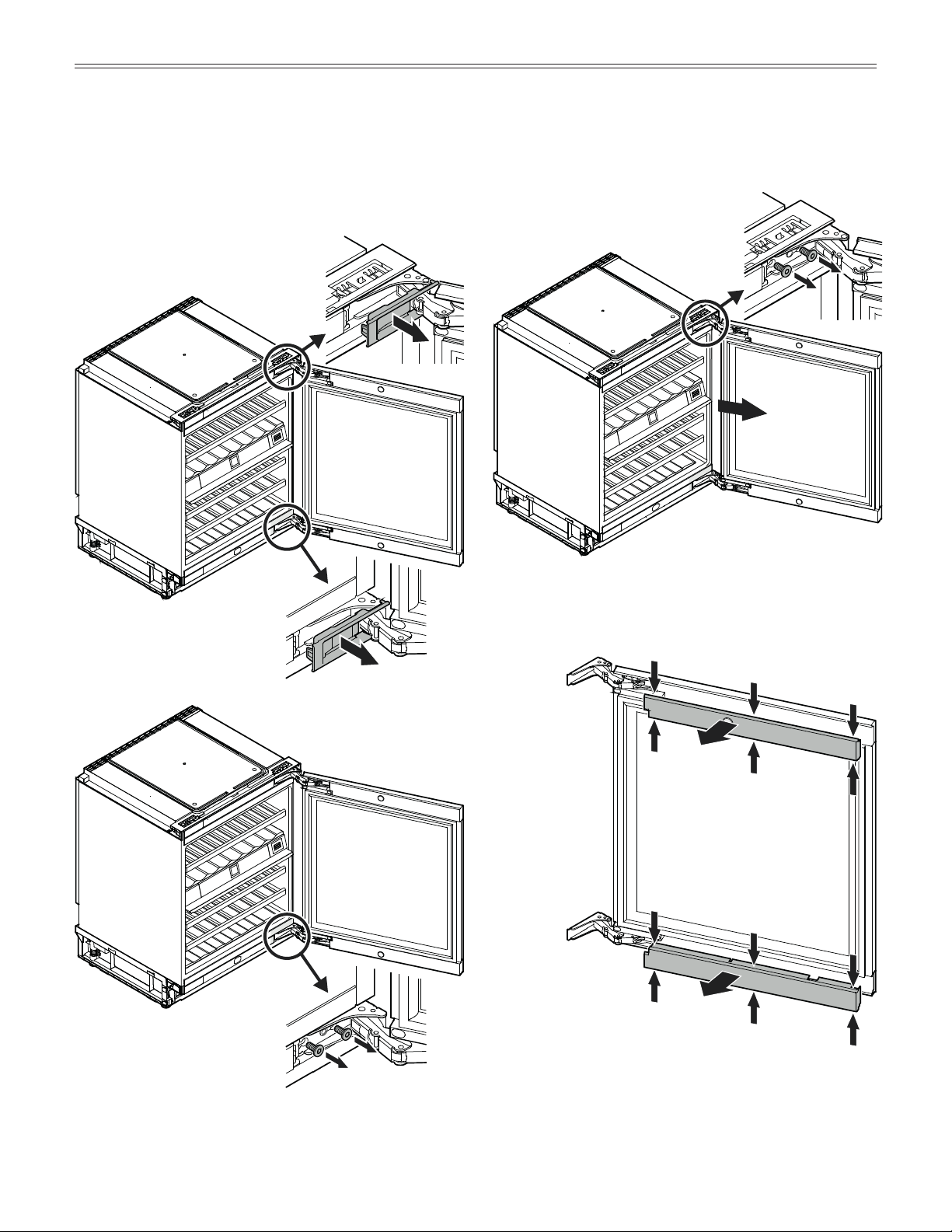
1.
2.
Important
The door must now be
held secure by another
person.
2. Remove screws from lower
hinge.
1. Remove covers.
3.
4.
5. Compress the covers in the places
shown, release and remove.
3. Remove screws from upper
hinge.
4. Remove door.
5.
C
hanging
o
ver
D
oor
h
inges
13
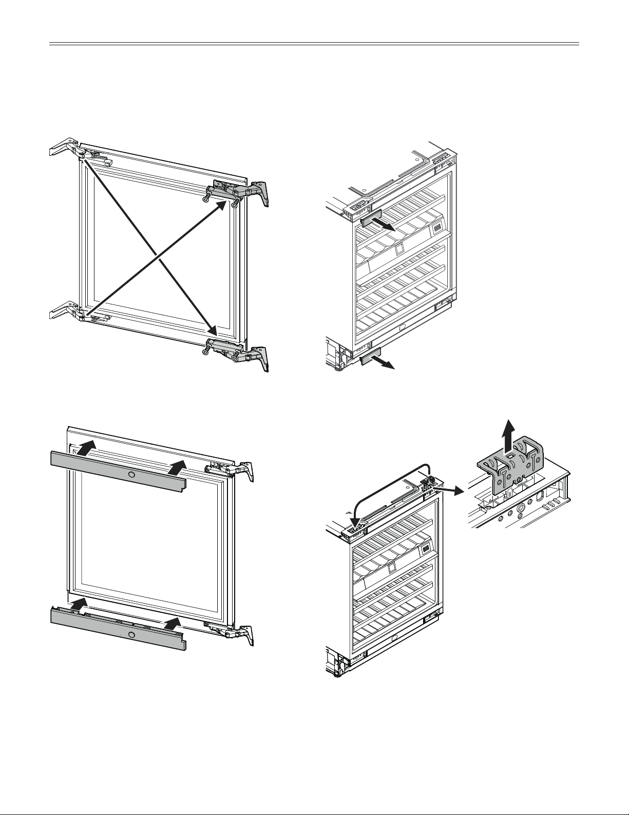
6.
6.Unscrewhingesandre-fitontheopposite
side at diagonals to the original position.
7.
7. Fit covers and click into place.
8.
9.
8. Remove the covers.
9. Remove the upper retaining brack-
et and transfer to the opposite
side.
C
hanging
o
ver
D
oor
h
inges
14
10.
10. Remove the lower retaining
bracket and transfer to the
opposite side.
11. Fit the door on the appliance.
Important
The door must now be held secure
by another person.
11.
12.
13.
C
hanging
o
ver
D
oor
h
inges
12. Screw on the hinge at the top
left.
Tighten screws.
13. Screw on the hinge at
the bottom left.
Tighten screws.
15
16.
15.
14. Close door and check
that it is aligned with
the side walls of the
appliance.
Adjusting the lateral tilt of the door
Ifthedoorisatanangle,adjusttheangle.
15. Undothescrews.
Align the door at the side.
Tighten screws.
14.
16. Fit covers.
C
hanging
o
ver
D
oor
h
inges

For Service in the U.S.
Liebherr Service Center
Toll Free: 1-866-LIEBHER or 1-866-543-2437
Email: Service-appliances.us@liebherr.com
PlusOne Solutions, Inc.
3501 Quadrangle Blvd, Suite 120
Orlando, FL 32817
For Service in Canada
Liebherr Service Center
Toll Free: 1-888-LIEBHER or 1-888-543-2437
www.euro-parts.ca
EURO-PARTS CANADA
39822 Belgrave Road
Belgrave, Ontario, N0G 1E0
Phone: (519) 357-3320
Fax: (519) 357-1326
www.liebherr-appliances.com
*708020002*