Loading ...
Loading ...
Loading ...
INSTALLATION OVERVIEW
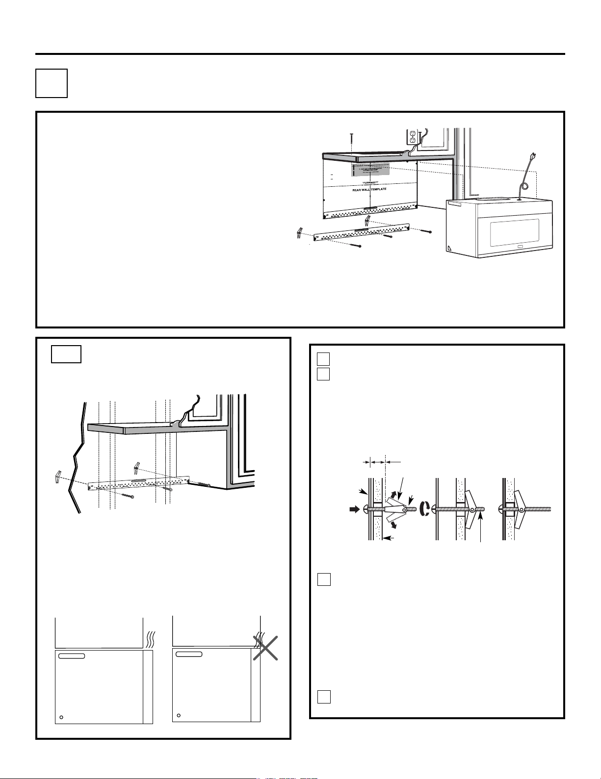
C1. Attach Mounting Plate to Wall
C2. Prepare Top Cabinet
C4.
C5.
Mount the Microwave Oven
IMPORTANT NOTES:
•
Make sure the screws for the blower motor and blower
plate are securely tightened when they are reinstalled.
This will help to prevent excessive vibration.
• Make sure the motor wiring has been properly routed
and secured, and that the wires are not pinched.
Installation Instructions
Place the mounting plate against the wall and
insert the toggle wings into the holes in the wall
to mount the plate.
NOTE: Before tightening toggle bolts and wood
screw, make sure the bott m of the mounting plate
touch the bottom of the cabinet when pushed flush
against the wall and that the plate is properly
centered under the cabinet.
CAUTION: Be careful to avoid pinching fingers
between the back of the mounting plate and the wall.
Tighten all bolts. Pull the plate away from the wall
to help tighten the bolts.
4
3
ATTACH THE MOUNTING
PLATE TO THE WALL
C1.
Attach the plate to the wall using toggle bolts.
At least one wood screw must be used to attach
the plate to a wall stud.
Remove the toggle wings from the bolts.
Insert the bolts into the mounting plate through
the holes designated to go into drywall and
reattach the toggle wings to
3
⁄
4
″ (19 mm) onto
each bolt.
1
Wall
Mounting
Plate
Spacing for Toggles
More Than Wall
Thickness
Bolt End
Toggle
Bolt
Toggle Wings
To use toggle bolts:
2
RECIRCULATING
(Non-Vented Ductless)
C
Install or change Charcoal Filter
C3. Check Blower Plate
NOTE:
Cabinet
Cabinet
If the cabinet depth including the cabinet doors
is more than 13""'' then the unit must be spaced
out from wall using adequate materials supporting
150 Ibs to allow proper top vent air exhaust/intake.
o
EN-20
3/8"TO
EDG
E
NOTE: IT IS VERY I
MPORTANT TO
READ AND FOLLOW
T
HEDIRECTIO
N
S
IN THE INSTALLAT
ION INSTRU
CTI
O
N
S
BE
FO
RE PR
O
CEEDING
WITH T
HIS
REAR W
A
LL TEM
PLATE.
This
Re
arWa
ll Templa
te ser
ve
s to position
th
e
b
ottom
mou
nting pl
a
te
and
to l
oc
ate the hori
z
onta
l e
x
hau
st
ou
tlet.
1
. Use a l
e
v
el
to
c
h
ec
k
that the te
m
pla
te
i
s po
s
itioned
a
ccu
r
ately
.
2. Locate
and
mark at least ones
tu
d
on the
le
ft or
r
ight
s
id
e
of th
e c
enterl
i
ne
.
It
is impo
rtan
t to u
s
e
at leas
t
one
wood
scre
w
mo
unted
fi
r
mly
i
n
a
s
tud
to support the w
eight
of
the mi
cr
owa
ve.
M
a
r
k
t
w
o
ad
di
ti
on
a
l, ev
e
nly
s
pa
c
ed
locations
f
or
the
s
uppl
ied to
g
gle bol
t
s.
3. Dr
ill
h
ol
e
s in
th
e m
ar
ked loc
ation
s
.
Wher
e t
h
er
e is
a stud,
dr
il
l a 3/16" hol
e
for wood sc
r
ew
s
.
F
o
r h
o
les
that
do
n
o
t lin
e upwith a
s
tu
d, d
ril
l 5/8
"
holes fo
r
to
gg
l
e bolts
.
DO NOT
INS
T
AL
L
THE
MO
U
NTI
NG PLATE
AT
T
HIS
TIME.
4. Re
mov
e th
e templa
te fro
m
the rea
r
wall.
5.Revie
wthe In
stall
ati
onInst
r
uctio
n book
for your
ins
ta
l
l
atio
n si
tuat
i
on
.
Locate and m
ar
k
holes
to ali
gn with holes in t
he
mountingplate.
IMPO
RTANT:
LOCA
T
E
AT LEA
ST
O
N
E
STUD
O
N EI
T
HER
SID
E O
F
TH
E CENT
E
RLIN
E.
MARK
THE LOCATIONFO
R 2 ADDIT
IO
NAL, EV
ENLY
SP
ACE
D TO
GGLE
BO
LTS
IN
THE MO
UN
TING
PLATE
AREA
.
Locate and mar
k
holes
to al
ign with holes
in t
he
mountingplate.
IMP
ORTANT
:
LO
C
AT
E AT LEAST O
NE
STUD
O
N EITHER SI
D
E OF
TH
E
CENT
E
R
LI
N
E
.
MARK
THE LO
CATIO
N
F
OR 2 ADDITIONAL, EVENLY
SP
ACED
TOGGLE BOLTS IN
THE MO
UN
TING
PLATE
AREA
.
Trim the re
ar
wall tem
plate along
the do
tted line.
Trim the rear wall templat
e along
the dotted line.
12"
4"
Da
rl
evue
lt
aa la ho
j
a
pa
rac
o
ns
u
lt
ar
la
v
ers
ión
enE
s
pa
ño
l.
Loading ...
Loading ...
Loading ...