Loading ...
Loading ...
Loading ...
6
Contents
•(1) Pair Prime Series Full Range Component Speakers
•(1) Pair of grilles/trim rings (R142, R152, R16, R165, R1675,
R1693 and R1694 only)
•Mounting Hardware
Installation Considerations
Before beginning any installation, follow these simple rules:
1. Be sure to carefully read and understand the instructions before
attempting to install these speakers.
2. For safety, disconnect the negative lead from the battery prior to
beginning the installation.
3. For easier assembly, we suggest you run all wires prior to mounting
your speakers in place.
4. Use high quality connectors for a reliable installation and to minimize
signal or power loss.
5. Think before you drill! Be careful not to cut or drill into gas tanks, fuel
lines, brake or hydraulic lines, vacuum lines or electrical wiring when
working on any vehicle. If installation in a boat, take care not to cut or
drill through the main hull.
6. Never run wires underneath the vehicle. Running the wires inside the
vehicle or hull area provides the best protection.
7. Avoid running wires over or through sharp edges. Use rubber or
plastic grommets to protect any wires routed through metal, especially
the firewall.
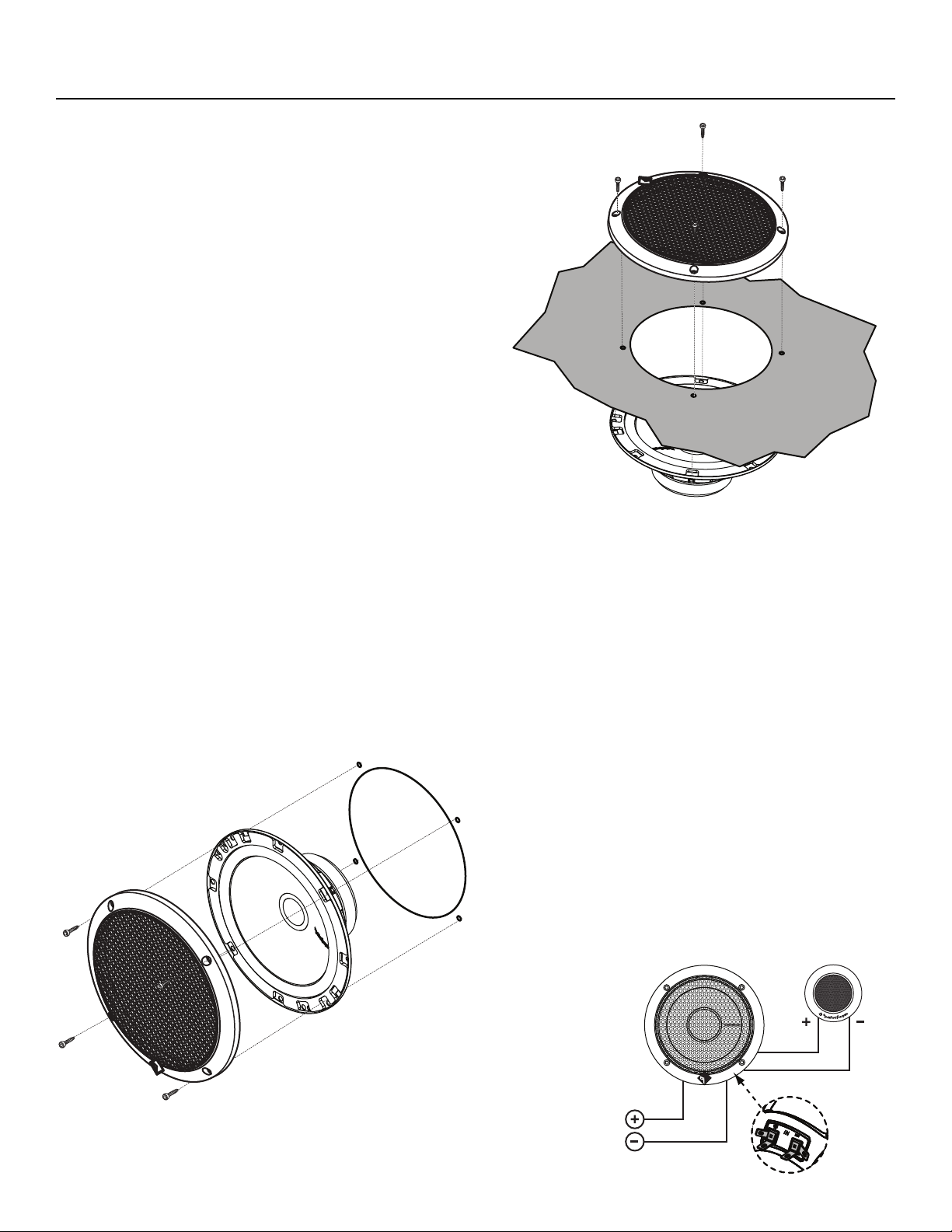
Mounting (illus.-2.1 & 2.2)
1. Determine where the speakers will be mounted. Ensure an area large
enough for the speaker to mount evenly. Be sure that the mounting
location is deep enough for the speaker to fit; if mounting in a door,
operate all functions (windows, locks, etc.) through their entire
operating range to ensure there is no obstruction.
2. Refer to the specification chart to determine the proper diameter hole
to cut for your speaker model. Cutting and mounting templates can be
found at www.rockfordfosgate.com.
3. Mark the locations for the mounting screws. Drill the holes with a
1/8” bit.
4. Feed the speaker wires through the cutout and connect to the speaker
terminals. Be sure to observe proper polarity when connecting the
wires.The speaker’s positive terminal is indicated with a “+”.
5. Fit the trim ring over the speaker and mount into place using four (4)
screws.
6. Tighten the screws until the speaker is snug in place to prevent
rattling. Do not over tighten the screws.
Wiring (illus.-3.1)
1. Use illustration for proper connection.
2. Be sure to maintain speaker polarity.
3. Connect primary tabs on Mid-Range/Woofer to Amplifier.
4. Connect secondary tabs on Mid-Range/Woofer to Tweeter.
NOTE: The tweeter has an integrated 6dB/octave HP crossover.The mid-
range/woofer has natural roll-off characteristics exhibit great acoustic
crossover filtering.
illus.-3.1
Installation
From Midrange
Mid-Range
Woofer
Tweeter
From Amplifier
illus.-2.1
Cutout
Hole
Example of standard
door installation
illus.-2.2
Rear
Deck
Cutout
Hole
Example of rear
deck installation
Loading ...
Loading ...
Loading ...