Loading ...
Loading ...
Loading ...
IMPORTANT: THESE INSTRUCTIONS SHOULD BE READ CAREFULLY AND RETAINED FOR FUTURE REFERENCE
IMPORTANT SAFETY ADVICE
DO NOT COVER OR OBSTRUCT the air inlet or outlet grille.
ENSURE THE APPLIANCE IS EARTHED.
Do not use this heater in areas where excessive dust exists.
This heater must not be located immediately above or below
a fixed socket outlet or connection box.
Always disconnect supply before working on the product.
This appliance should only be connected to the fixed wiring
of the premises by means of conduit.
This product should be mounted safely to solid wall or ceiling
surfaces only.
This product must not be subjected to water spray or
immersion.
Ensure the supply cables are of adequate current carrying
capacity and are protected by a suitable fuse / circuit
breaker.
Ensure proper manual handling procedures are
observed at all times.
WARNING: Isolate electrical supply to ALL modular linked
units when carrying out maintenance.
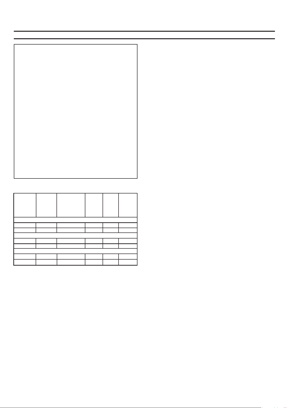
Models
Heat Electrical Electrical Weight Max
Model Output Supply load Installed
(per phase) height
kW A kg m
AMBIENT / COLD STORE
IAB10A n/a 220-240V ~1PN 8.5 80 6.0
IAB15A n/a 220-240V ~1PN 12.6 120 6.0
ELECTRICALLY HEATED
IAB10E 12 / 24 kW 380-415V ~3PN 42 80 6.0
IAB15E 18 / 36 kW 380-415V ~3PN 63 120 6.0
WATER HEATED (at 82/71 °C - LPHW)**
IAB10W 27 220-240V ~1PN 8.5 80 6.0
IAB15W 41 220-240V ~1PN 12.6 120 6.0
Electrical
The installation of this appliance should be carried out by a
competent electrician and be in accordance with the current IEE
wiring regulations.
Installation
This appliance may be either wall-mounted or fixed to a ceiling -
see Fig. 3a & 3b for fixing positions and ‘Mounting’ sections
below for fixing details.
A minimum distance of 500mm is required from the top of the
appliance to ceiling - see ‘a’ in Fig. 1.
The distance between the bottom of the appliance and the top of
a door should be kept to a minimum - see ‘b’ in Fig. 1.
Wall Mounting
A suitable load bearing structure (not supplied) is required to
wall mount the appliance, see Fig. 3a. (see Fig. 6 for fixing
dimensions).
Ceiling Mounting
Lift the appliance into position using suitable lifting equipment.
(You may use the pallet supplied with the unit). Secure the
appliance into position using M12 threaded bar and locknuts as
shown in Fig. 3b (see Fig. 6 for fixing dimensions).
Dimplex Industrial Air Curtains
Models : IAB10E, IAB15E, IAB10W, IAB15W, IAB10A, & IAB15A
Electrical connection
All products are fitted with a microprocessor control. Electrical
power and control connections are made as shown in Fig. 2. A
suitable local isolating switch must be provided in the electrical
supply circuit with at least 3mm clearance on each pole.
In order to access the electrical connections, remove the air
supply grille (‘g’ in Fig. 2) and the front panel (‘f’ in Fig. 2).
Feed an appropriate supply cable (see ‘e’ in Fig. 2) through a
suitable cable gland (not supplied) fitted in the top panel and
attach to the Mains In Terminal Block (see ‘d’ in Fig. 2).
A suitable cable for the supplied switch panel can be similarly
introduced and connected to the circuit board. If the unit is to be
operated in conjunction with a door switch, a normally closed
switch should be wired as per Fig. 4 & 5 as appropriate - see
also ‘Switch Panel Instructions’.
If the unit is to be connected to a Building Energy Management
System, connections are made as per ‘G’ in Fig. 4 & 5 as
appropriate.
Water connection
Models designed for use in conjunction with a low pressure hot
water supply should be individually connected (in a parallel
circuit) to the flow and return pipe-work. Connections (see ‘a’ in
Fig. 2) are: 1” BSPT and isolation valves (see ‘b’ in Fig. 2) should
be fitted as close to the air curtain connection points as possible.
For commissioning, air bleed valves (see ‘c’ in Fig. 2) are fitted
to the coil, which can be accessed from outside the unit.
Maximum water supply conditions are 110ºC and 10 bar
(1MPa).
Ensure that the air curtain is securely fastened in position and
that the supply cables are firmly clamped before operating the
appliance.
Operation using Switch Panel
Electrically heated variants
When first turned on the control will run through a system check.
The selected settings will be reached and maintained after a
one minute period.
Switch on electrical supply to the air curtain. Switching the switch
marked ‘I’ energises the fan. The fan switch allows either low or
high fan speeds to be selected. The heat selection switch allows
heat setting to be chosen.
- Off
- ½ heat
- Full heat
The A / M (auto / manual) switch allows for manual over-ride of a
door switch if fitted.
The unit should always be switched OFF using the switch panel
control, and not by mains power supply interruption.
When the unit is switched off (via the switch panel) the fan will
run on for 1 minute without heat to discharge any residual energy
from the heating elements.
Door switch control
By including a door switch in the circuit (as per ‘D’ in Fig. 5) the
air curtain will respond to door openings as follows:
(1) Door opening will energise the air curtain at the set
conditions (switch panel settings).
(2) On door closure operation will continue at the set conditions
for a further 1 minute.
(3) Between 1 minute and 2 minutes from door closure, set
back operation, ½ heat (if heat selected) and ½ fan will
activate.
Loading ...
Loading ...
Loading ...