
ControlSpace
®
SP-24 Editor
Software User's Guide


Table of
Contents
Introduction .................................................................................................. 3
Additional Resources ...................................................................................... 3
Getting Started .............................................................................................. 5
Minimum System Requirements .................................................................... 5
Software Installation ................................................................................... 5
Device Connections ..................................................................................... 6
Software Interface ......................................................................................... 9
User Interface: SP-24 Editor ......................................................................... 9
Overview ................................................................................................. 9
User Interface Components .......................................................................... 9
Signal Processing Map............................................................................... 9
Block Type............................................................................................. 10
Active State ........................................................................................... 10
Inactive State ........................................................................................ 10
Right-click Options.................................................................................. 10
Input and Output Meters ......................................................................... 11
Processing Control Panel ......................................................................... 11
Toolbar Reference ..................................................................................... 12
Menu reference ......................................................................................... 13
The File Menu ........................................................................................ 13
The SP-24 menu .................................................................................... 14
The Help menu....................................................................................... 14
Configuring the SP-24 Processor .................................................................... 17
Signal Processing Functions ........................................................................ 17
Input Level Control ................................................................................. 17
Router .................................................................................................. 18
Input/Output 9-Band DualEQ ................................................................... 18
Band Pass Crossover............................................................................... 20
BOSE® Loudspeaker Equalization............................................................. 21
Signal Delay .......................................................................................... 23
Output Signal Limiter .............................................................................. 24
Output Level Control ............................................................................... 24
iii

ControlSpace
®
SP-24 Editor Software User's Guide
Working with Scenes ................................................................................. 25
Working with scenes ............................................................................... 25
Creating a new scene.............................................................................. 25
Saving a Scene to a file ........................................................................... 25
Opening a Scene from a file ..................................................................... 26
Clear a Scene from the hardware ............................................................. 26
Recall a Scene from the Editor software .................................................... 26
Store a Scene to hardware ...................................................................... 27
Application Examples.................................................................................... 29
Application examples ................................................................................. 29
Dual Mono Configuration ............................................................................ 30
Bose Bass Array Configurations................................................................... 31
Maintenance ................................................................................................ 33
Upgrading SP-24 Firmware ......................................................................... 33
Upgrading the Bose Loudspeaker EQ Database within the SP-24 Sound Processor
............................................................................................................... 38
Upgrading an Existing System to the SP-24 Sound Processor.......................... 42
iv

1


3
Introduction
ControlSpace
®
SP-24 Editor software provides access to all signal processing
functions within the Bose SP-24 sound processor. Using the SP-24 Editor software
you can define signal processing parameters and store them as custom Scenes
while either on or offline. The SP-24 Editor software is also used to update the
ControlSpace SP-24 sound processor’s firmware and Bose loudspeaker equalization
database.
The ControlSpace SP-24 sound processor is only configured using the SP-24
Editor software. It is not possible to configure the SP-24 sound processor using
the ControlSpace Designer™ software.
Additional Resources
Additional information on the use and configuration of the ControlSpace SP-24
sound processor can be found at
http://pro.bose.com.
Application questions can be directed to the Bose system electronics users’ forum.

5
Getting Started
Minimum System Requirements
•
Microsoft® Windows® XP Professional, Service Pack 2 (or later)
•
Microsoft Windows 7 (Professional or Ultimate)
•
Intel® Pentium® 4 - 850 MHz processor (or better)
•
Minimum screen resolution of 1280x768
•
512 MB RAM
•
100 MB disk space available
Software Installation
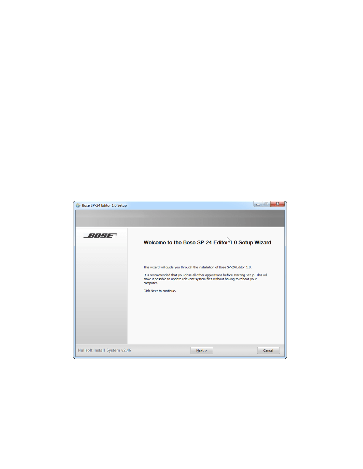
1. Double-click on SP-24_Setup.exe to install the software.
Fig. 1.1- Application Installer Dialog
2. Click Next to begin installation.
3. Follow the prompts to install the SP-24 Editor software onto your
computer.
4. Click Finish when installation is complete

6
ControlSpace
®
SP-24 Editor Software User's Guide
Fig. 1.2- Bose SP-24 Editor 1.0 Setup
Device Connections
The SP24 Editor software communicates with the hardware via a standard USB
connection, using the standard human interface device, (HID), USB controller.
Once a connection is initiated between the PC and hardware the device will be
recognized and added to the list of available devices.
Once the processor is connected to the PC via USB, and is powered on, it can be
accessed and controlled using the SP24 Editor software.
1) Establish a USB connection between the SP-24 and the PC. Make sure the
SP-24 is powered on, and recognized by the PC.
7
Getting Started
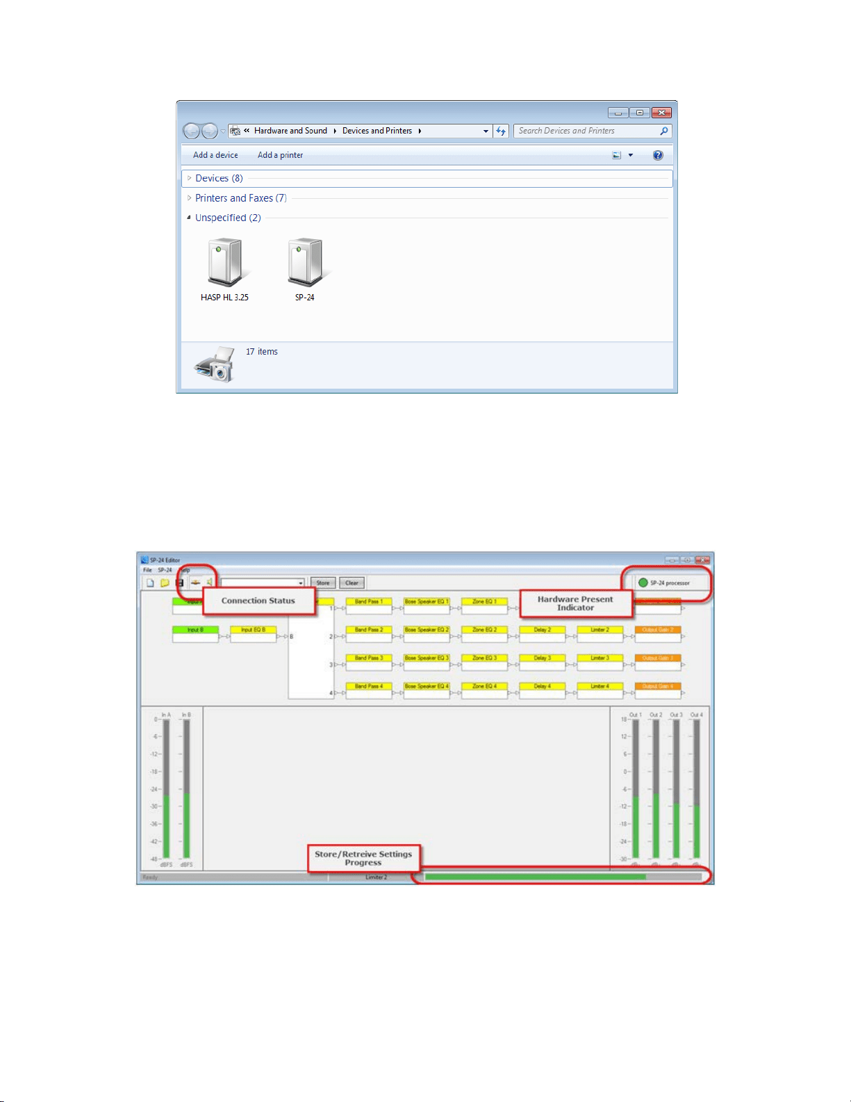
Fig. 1.3- Devices and Printers panel
2) Launch the PC Editor Software
a. The SP 24 processor is automatically detected and a connection is
established.
Fig. 1.4- SP-24 Editor Software Connection
3) You are now connected to the SP-24 sound processor and can configure
the processor for operation.
ControlSpace
®
SP-24 Editor Software User's Guide
8
Fig. 1.5- SP-24 Editor interface
9
Software Interface
User Interface: SP-24 Editor
Overview
To begin, launch the SP-24 editor software by choosing Start > All Programs >
Bose > SP24 Editor.
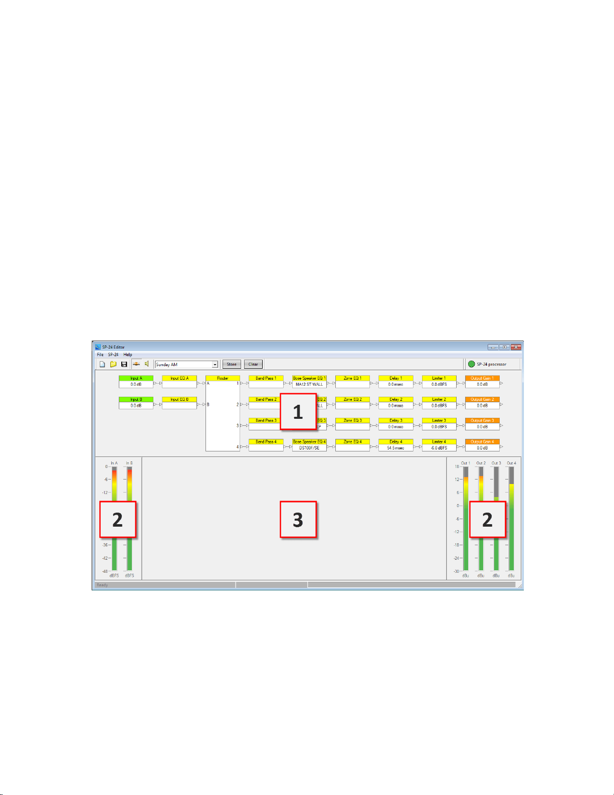
The SP-24 Editor user interface consists of three primary components:
•
Signal Processing Map (1)
•
Input/Output Meters (2)
•
Processing Control Panel (3)
Additional functions are available within the application menus and tool bar, but
these three elements serve as the primary application interface.
Fig. 2.1- User interface
User Interface Components
Signal Processing Map
The Signal Processing Map is the primary component within the application
interface, and displays the available signal processing functions within the SP-24
processor. The wiring of individual processing blocks represents the signal flow of
ControlSpace
®
SP-24 Editor Software User's Guide
10
the unit. To configure an individual processing function select its icon in the Signal
Processing Map. You can then access its control panel within the Processing Control
Panel section (3) of the application interface.
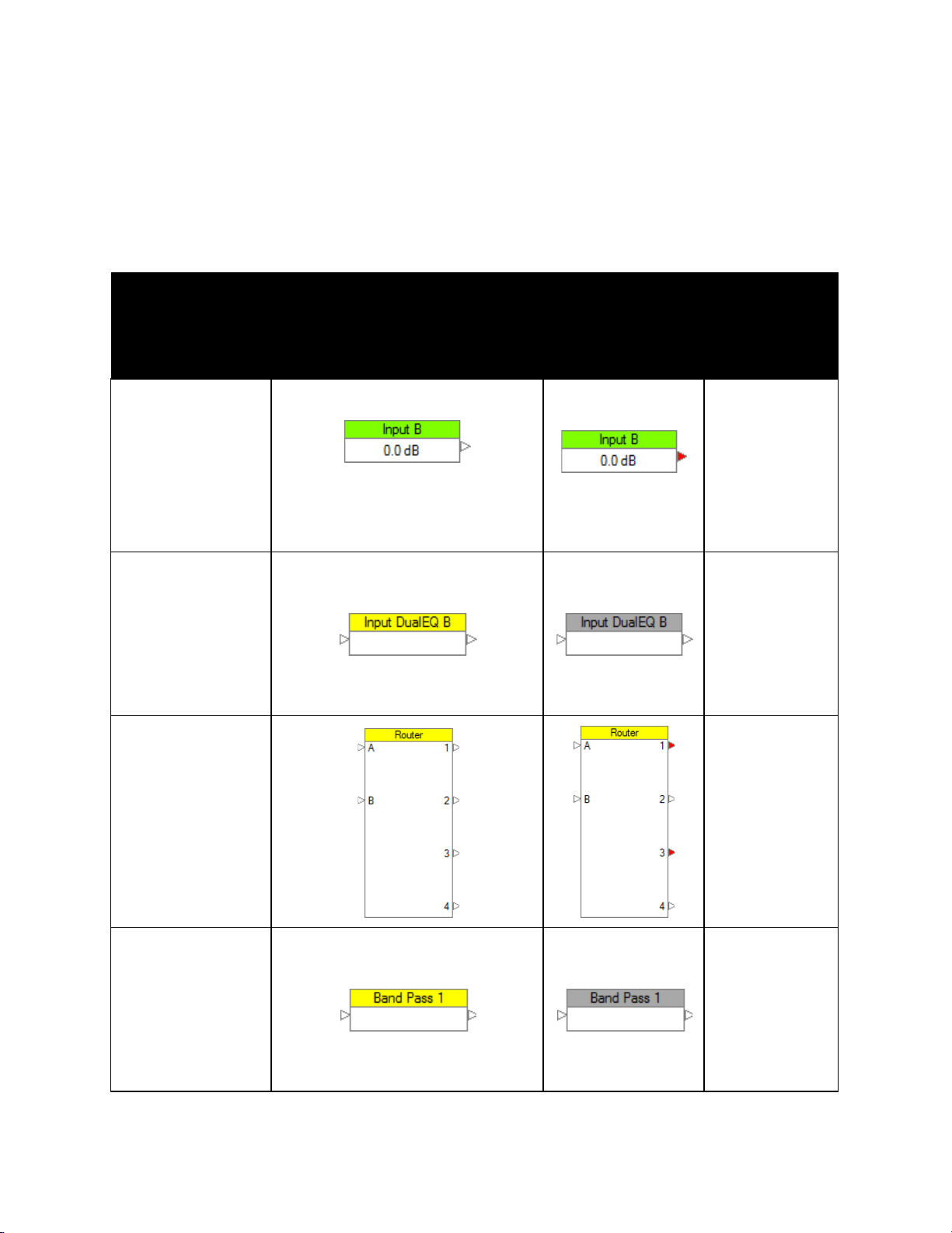
Within the Signal Processing Map, the status of the individual signal processing
block is indicated using the following methods:
Right-
Block Type Active State
Inactive
click
State
Options
Input &
Output
Current signal level
displayed within block
Output Muted
Copy
Parameters
Paste
parameters
Mute/
Unmute
Input & Zone
DualEQ
Copy
Parameters
Paste
Parameters
Bypass/
Enable
Router
N/A
Band Pass
Copy
Parameters
Paste
Parameters
Bypass/
Enable
Software Interface
11
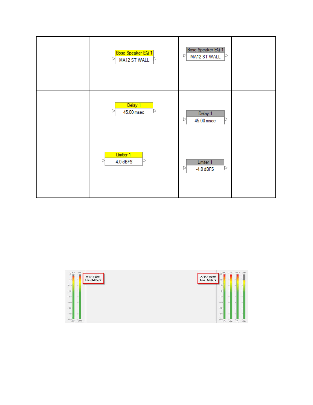
Bose
Loudspeaker
Preset
Current Bose Loudspeaker
EQ setting displayed within
block
Copy
Parameters
Paste
Parameters
Bypass/
Enable
Signal Delay
Current Signal Delay setting
displayed within block
Copy
Parameters
Paste
Parameters
Bypass/
Enable
Signal Limiter
Current
signal limiter threshold
displayed within block
Copy
Parameters
Paste
Parameters
Bypass/
Enable
Table 1: Methods used to indicate the status of the individual signal processing block
Input and Output Meters
The input and output signal levels are displayed to the left and right of the
Processing Control Panel section. Input signal meters represent the signal level in
dBFS as scaled by the Max Input Level setting. Output signal level meters represent
the output signal level of the processor in dBu.
Fig. 2.2- Input and Output meters
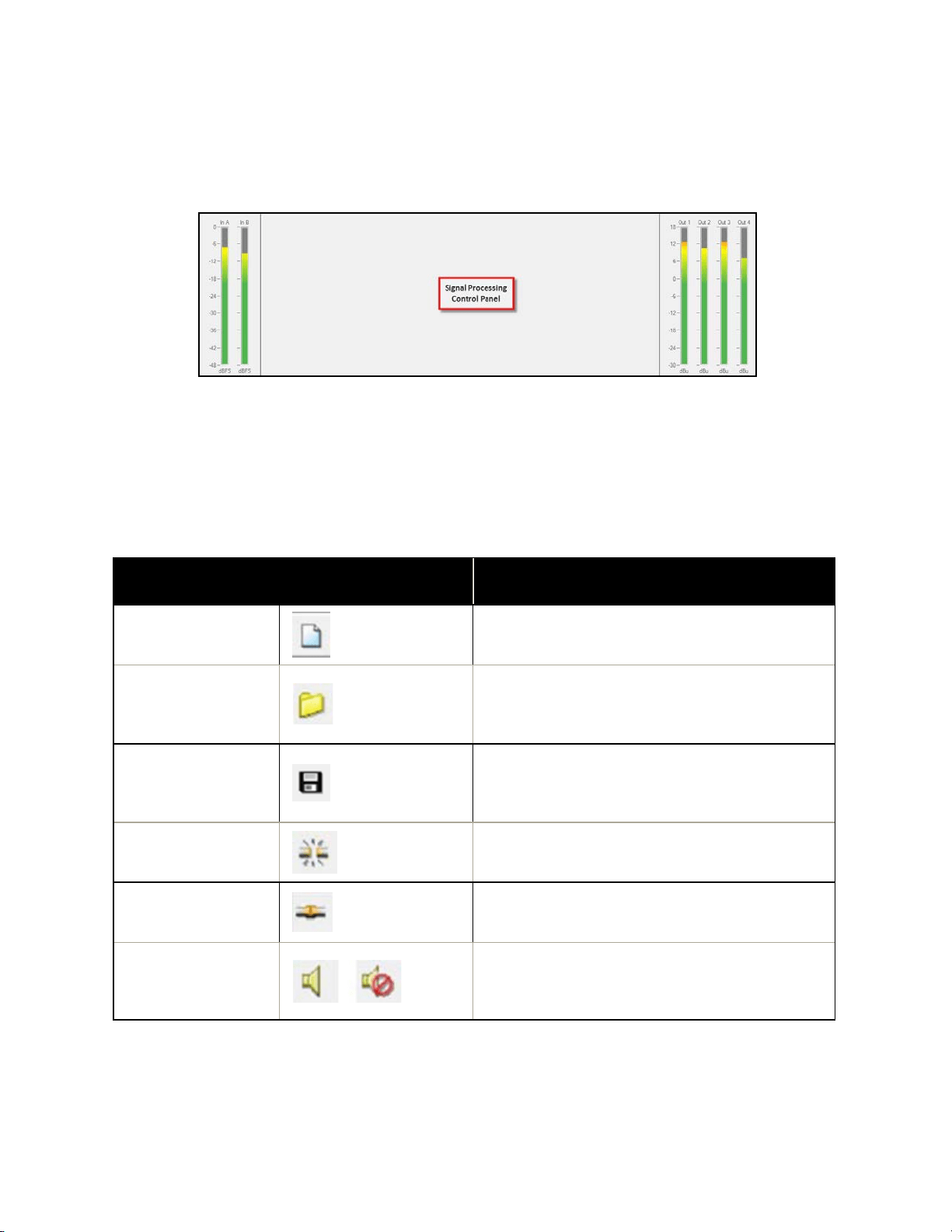
Processing Control Panel
ControlSpace
®
SP-24 Editor Software User's Guide
12
The Processing Control Panel displays the control functions of the selected signal
processing block. When no processing function is selected the Control Panel is
empty.
Fig. 2.3- Processing Control Panel
Toolbar Reference
The application toolbar provides quick access to the most common functions within
the SP-24 Editor software.
Toolbar Item
Function
New Scene
Resets all signal processing parameters to
their default
Open Scene
Launches the File Open dialog so a new
Scene may be opened and applied to the
SP-24 processor
Save Scene
Saves the current signal processing
parameters as a Scene to the local hard
drive
Go Online
Toggles the online/offline state of the
hardware
Go Offline
Toggles the online/offline state of the
hardware
Mute/ Unmute
Controls audio output (This function in
only available when connected to the SP-
24.)
Software Interface
13
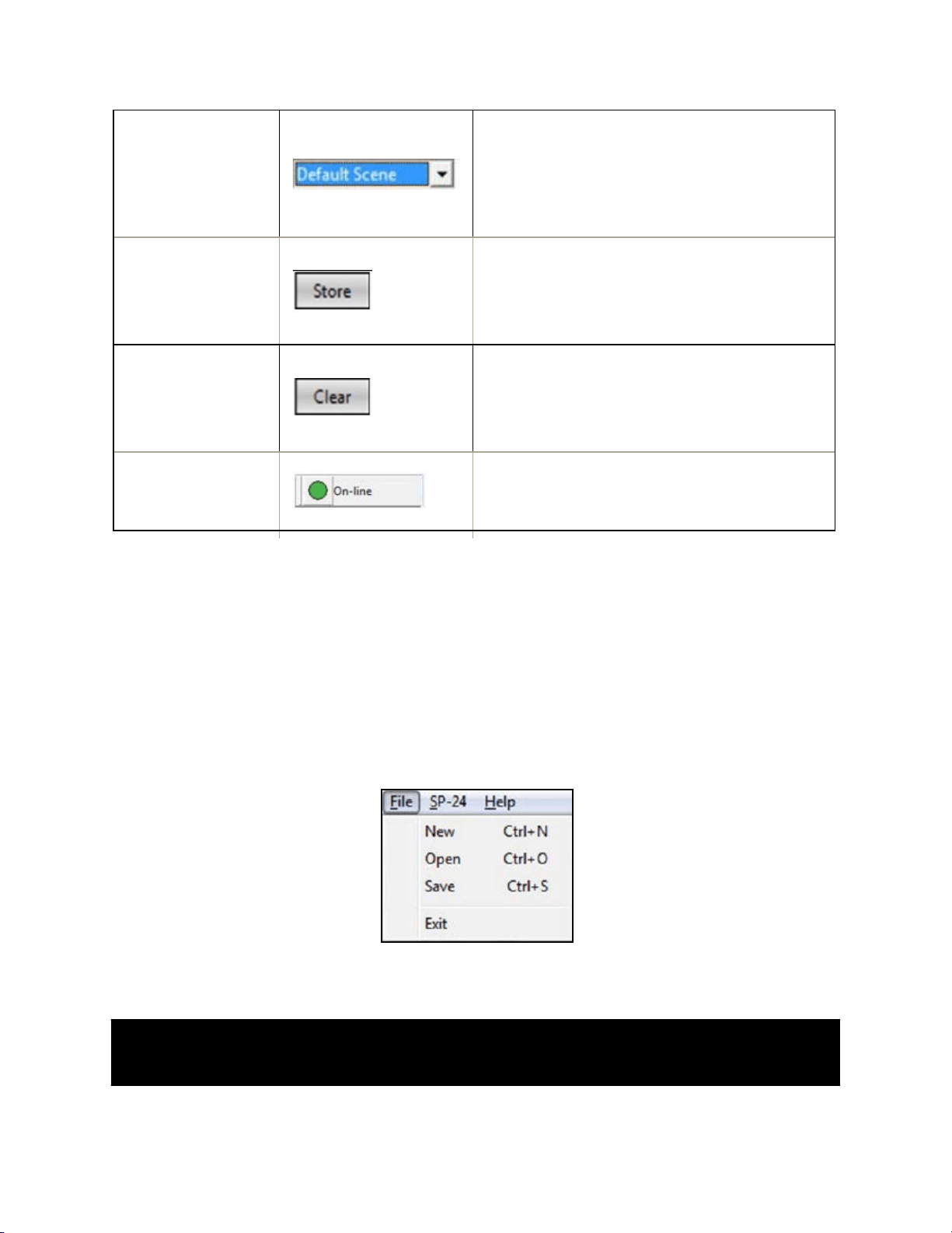
Scene Select
Displays the currently active Scene, and
provides access to the each of the four
Scene Banks
(This function is available only when
connected to the SP-24.)
Store Scene
Stores the current hardware settings to
one of the four Scene Banks
(This function is only available when
connected to the SP-24.)
Clear Scene
Clears the selected (one of the four Scene
Banks) Scene
(This function is only available when
connected to the SP-24.)
Hardware
Preset
Indicator
Indicates that an SP-24 is actively
connected to the PC
Table 2: Functions available in the Toolbar
Menu reference
The SP-24 Editor menu bar offers three main menus: File menu, SP-24 menu and
Help menu.
The File Menu
Refer Fig. 2.4 and Table 3 for detail information on the File menu.
Fig. 2.4- The File menu
Menu
Item
Function
ControlSpace
®
SP-24 Editor Software User's Guide
14
New
Creates a new SP-24 Editor Scene file (.scn). (selecting this item while
online will cause the currently active Scene to be replaced with a set of
default settings.)
Open
Opens an existing file located on the local hard drive
Save
Saves the current signal processing parameters as a Scene
Table 3: File menu- menu items with respective
functions
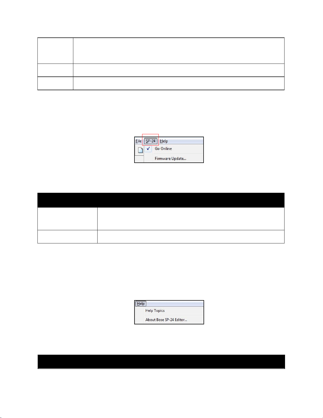
The SP-24 menu
Refer Fig. 2.5 and Table 4 for detail information on the SP-24 menu.
Fig. 2.5- The SP-24
menu
Menu Item Function
Go Online
Toggles the online/offline state of the hardware.
(Check mark- appears as an indicator when Online with an SP-24)
Firmware Update
Updates the firmware within the SP-24 hardware
Table 4: SP-24 Menu- menu items with respective functions
The Help menu
Refer Fig. 2.6 and Table 5 for detail information on the Help menu.
Fig. 2.6- The Help menu
Menu Item Function

Software Interface
15
Help Topics
Displays the SP-24 Editor online help
About Bose SP-
24 Editor
Displays information about Bose SP-24 Editor software like the
current firmware version of the hardware
Table 5: Help Menu- menu items with respective functions

17
Configuring the SP-24 Processor
Signal Processing Functions
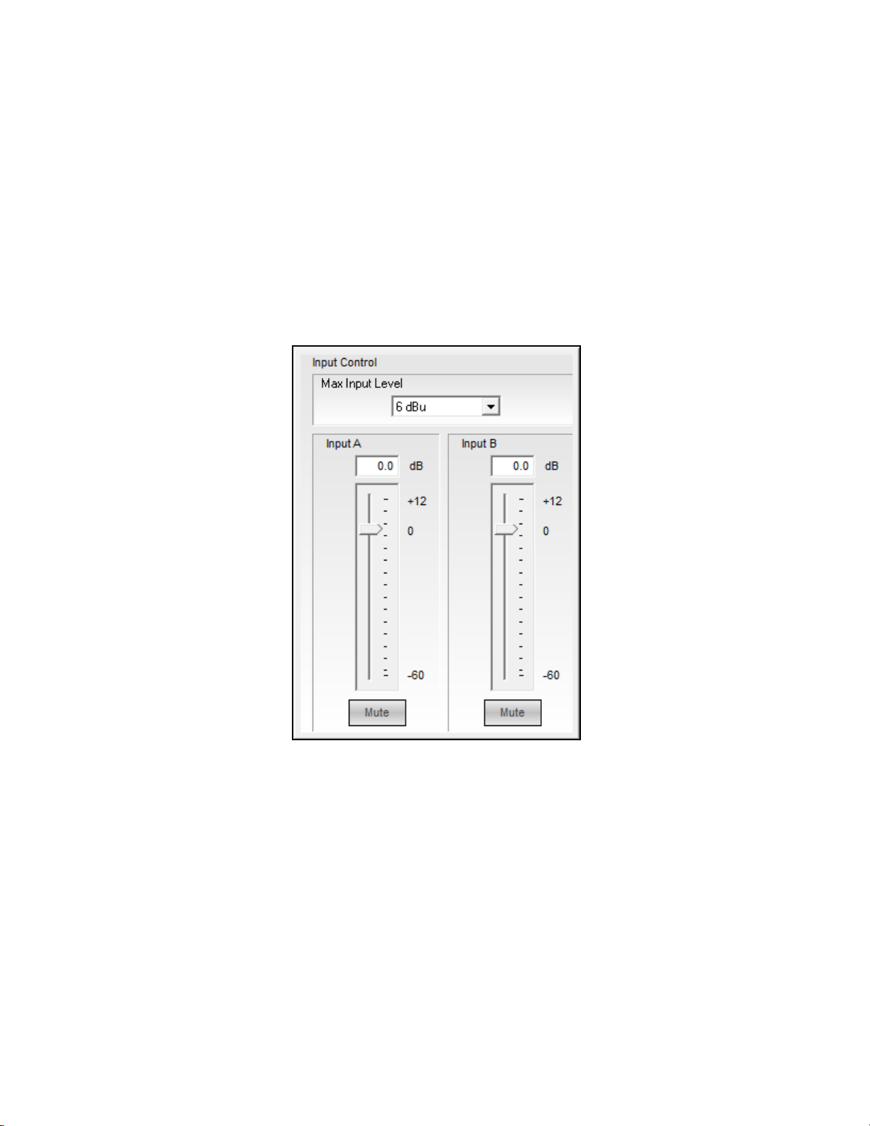
Input Level Control
The Input Level control provides access to the analog sensitivity and digital input
gain controls. Input Level controls are accessed by selecting either of the two Input
Level signal processing blocks within the Signal Processing Map.
Fig. 3.1- Input Control Panel
Input Level – This adjustment is in the analog domain, pre analog-to-digital
conversion. Select the desired maximum input level, in dBFS, that matches
the maximum output level capability of the source (as indicated in the
manufacturer's documentation). Sources that exceed +18 dBFS should have
their output signals regulated as to not overload the input of the SP-24 Sound
Processor.
Input Gain Value – Permits direct text entry of desired input signal level in
dBFS. Range of adjustment matches and tracks the input gain slider.
Input Gain Slider – Adjusts the input signal level delivered to the next gain
stage. The range of adjustment is from –60 to +12 dBFS. This adjustment
point is in the digital domain, post analog to digital conversion.
18
ControlSpace
®
SP-24 Editor Software User's Guide
Mute – Silences the signal and disables audio from passing to the next gain
stage in the design. When Mute is enabled, the control panel button is Red.
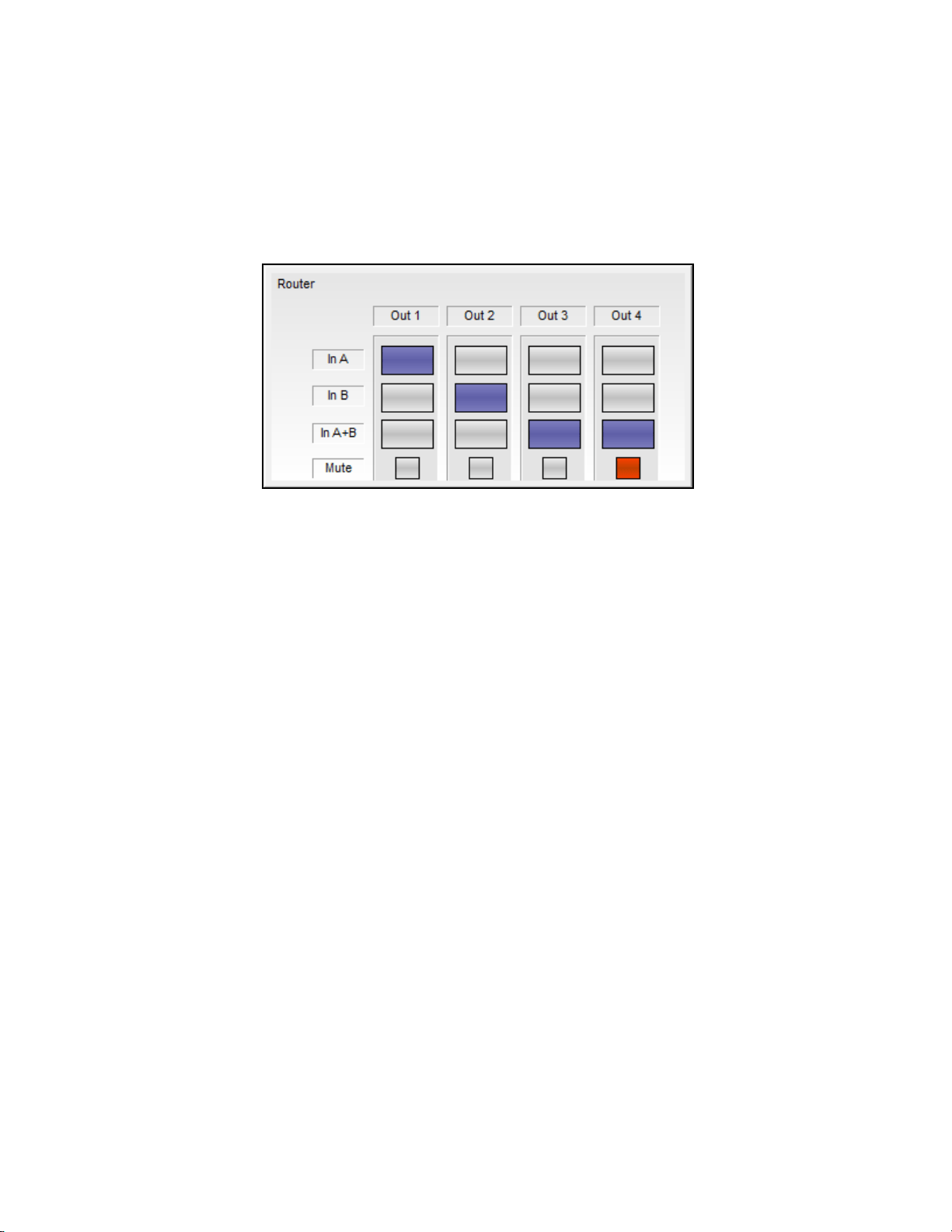
Router
The router assigns the A and B inputs to each of the four output channels. Each
output may accept input A, input B or mono sum of Input A+B.
Fig. 3.2- SP-24 Router Control Panel
Within the Router control panel the following functions are available:
Route Input A to Output n – Selecting input A for any of the four output
channels routes input A to the selected output.
Route Input B to Output n – Selecting input B for any of the four output
channels routes input B to the selected output.
Route Inputs A+B to Output n – Selecting inputs A+B for any of the four
output channels will route a mono sum of inputs A+B to the selected output.
When operating in this mode a 6 dB attenuation is applied to the output of
the router to balance the output level between single and summed channel.
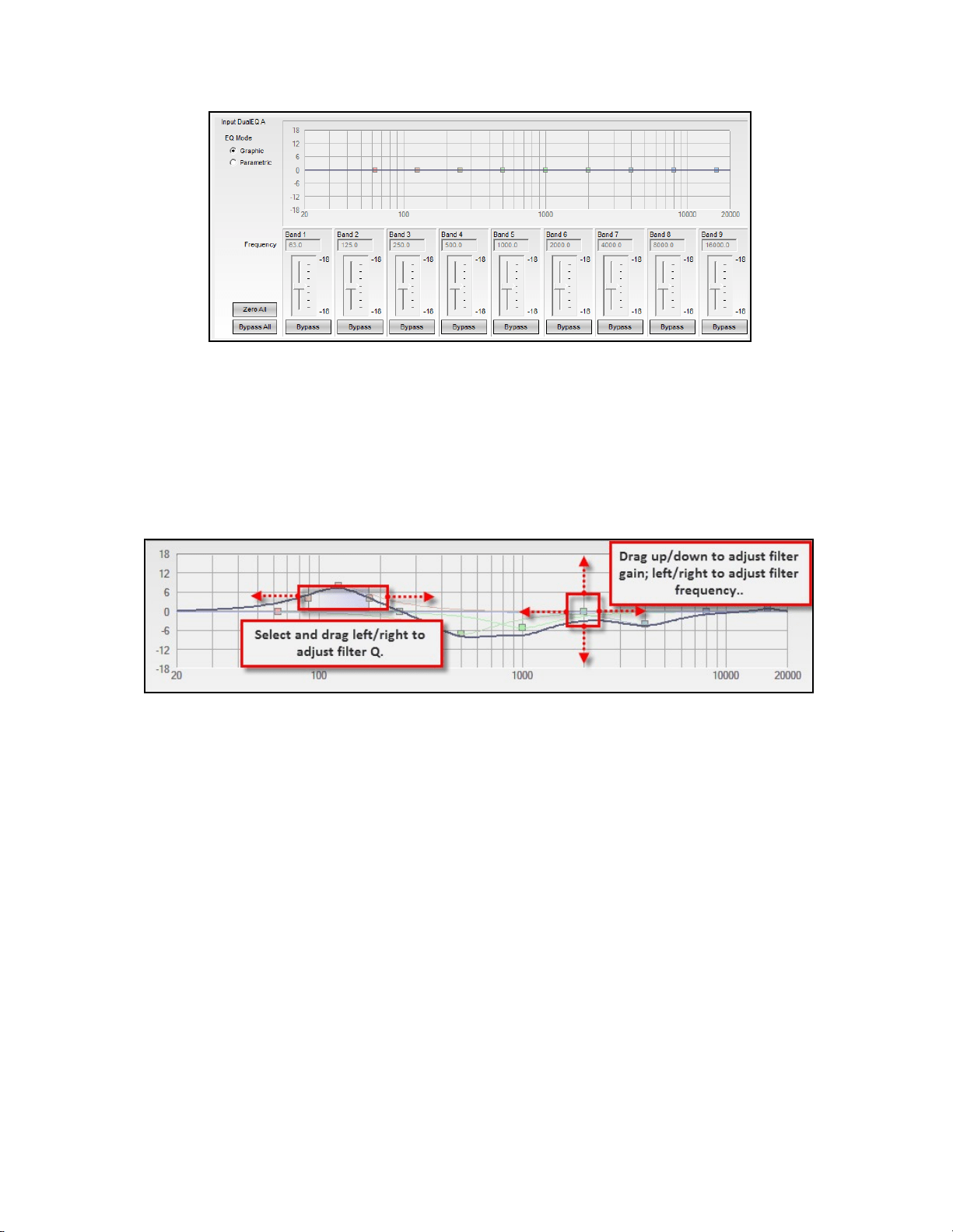
Input/Output 9-Band DualEQ
Each input and output signal processing chain includes a 9-band DualEQ, which can
be operated as a 9-band graphic equalizer, or as a 9-band parametric equalizer.
Graphic EQ Mode
The graphic EQ mode is the default operating mode for each Input/Output DualEQ.
Each of the nine filter bands operates at a fixed octave-band center, and gain for
each band is available using the gain slider controls.
19
Configuring the SP-24 Processor
Fig. 3.3- DualEQ
The following controls and functions are available in the graphic EQ mode:
DualEQ Mode – is used to select between Graphic and Parametric EQ mode
Response Graph – Displays the overall EQ response, and the response curve
of individual filter bands. Each filter band can be manually adjusted using the
filter’s grab handle.
Fig. 3.4- Response Graph
Filter Gain Slider – is used to adjust the filter gain by +/-18 dB
Bypass – is used to Bypass the filter stage
Bypass All – is used to Bypass all filter stages
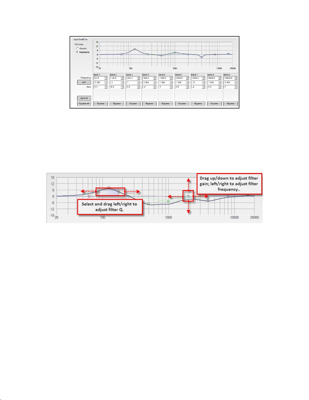
Parametric EQ Mode
The Parametric EQ mode is the optional operating mode for each Input/Output
DualEQ. In this mode, control over the Frequency, Q and Gain of each filter stage is
available.
ControlSpace
®
SP-24 Editor Software User's Guide
20
Fig. 3.5- Parametric EQ Mode
In parametric EQ mode the following controls and functions are available:
DualEQ Mode – is used to select between Graphic and Parametric EQ mode
Response Graph – Displays the overall EQ response, and the response curve
of individual filter bands. Each filter band may be manually adjusted using
the filter’s grab handle.
Fig. 3.6- Filter manipulation in parametric mode
Frequency – Enter the desired center frequency for the filter
Bandwidth/Q – Select the BW/Q to switch between entering the filter width
as bandwidth or Q
Filter Gain Slider – Adjust the filter gain by +/-18 dB
Bypass – Bypass the filter stage
Bypass All – Bypass all filter stages
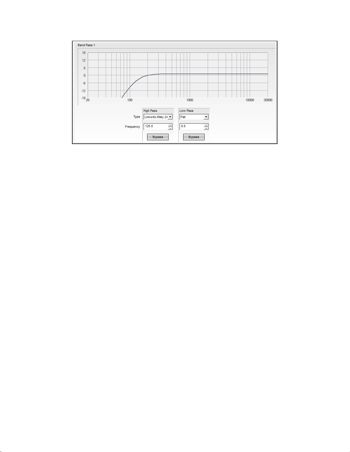
Band Pass Crossover
The Band Pass Crossover function provides a single mono crossover for the output
signal processing chain.
To access the Band Pass Crossover control panel, select the block within the signal
processing map. The default state of the Band Pass Crossover has no filters
implemented in order to provide a flat initial response.
Configuring the SP-24 Processor
21
Fig. 3.7- Band Pass Crossover
The following controls are available within the crossover block:
Response Graph – Displays the response curve of the High and Low Pass
filter settings.
Loudspeaker Preset – When a Bose loudspeaker EQ preset, which contains
a high/low pass section, is applied via the front panel, the selection in the
band type reads 'Preset Specific.'
High Pass Filter Type – Affects the low frequency cut off of the crossover.
Available filter types are Butterworth (1st, 2nd, 3rd, 4th, 6th and 8th order),
Bessel (1st, 2nd, 3rd, 4th, 6th and 8th order), and Bessel (2nd, 4th, 6th and
8th order).
High Pass Frequency – Defines the corner frequency of the filter.
High Pass Bypass – When active the high pass filter is bypassed.
Low Pass Filter Type – Affects the high frequency cut off of the crossover.
Available filter types are Butterworth (1st, 2nd, 3rd, 4th, 6th and 8th order),
Bessel (1st, 2nd, 3rd, 4th, 6th and 8th order), and Bessel (2nd, 4th, 6th and
8th order).
Low Pass Frequency – Defines the corner frequency of the filter.
Low Pass Bypass – When active the low pass filter is bypassed.
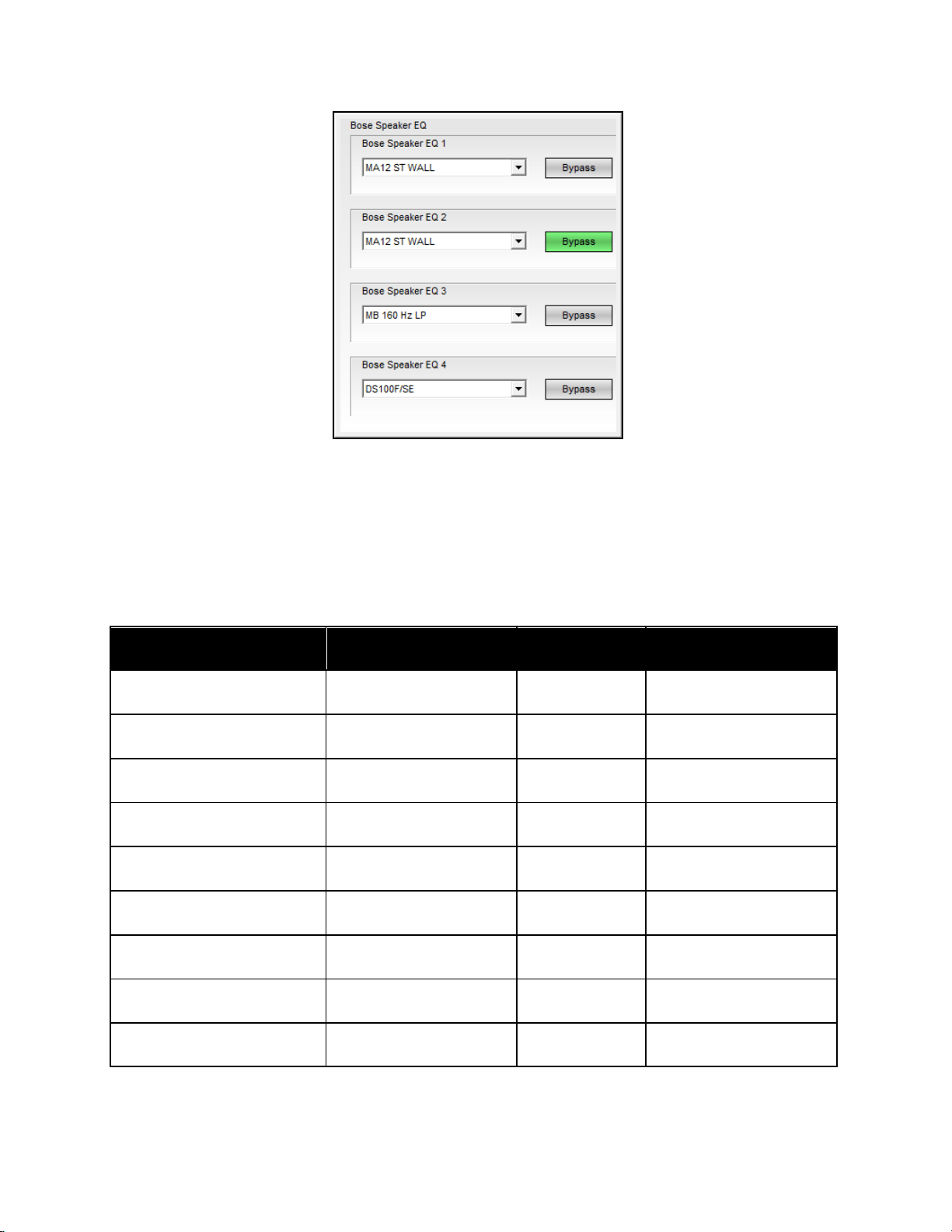
BOSE
®
Loudspeaker Equalization
Each output signal processing chain includes a dedicated Bose loudspeaker EQ
stage. Selecting any one of the four loudspeaker EQ blocks will cause the combined
control panel for all loudspeaker EQs to be displayed.
ControlSpace
®
SP-24 Editor Software User's Guide
22
Fig. 3.8- EQ Control panel
Bose
®
EQ Preset (channel) – Use the Loudspeaker EQ drop down control to select
the desired Bose professional loudspeaker product EQ.
Bypass – Bypasses the loudspeaker EQ stage for the selected channel.
The following Bose loudspeaker equalization curves are available within the SP-24
sound processor.
FreeSpace
®
Products
Panaray
®
Products
LT Products
Legacy EQ Curves
DS16 F/S/SE
402II
LT6400
402-I
DS16F PNDT
502A
LT9400
502BEX
DS40F/SE
502B
LT3202
802-II
DS40F PNDT
802III
LT4402
802-II ST
DS100F/SE
802III ST
LT9402
LT3202-I
DS100F PNDT
MA12 Wall
LT9702
LT3202-I Cluster
FS3 100Hz LP
MA12 Free
LT6403
LT4402-I
FS3 150Hz LP
MA12 ST WALL
LT9403
LT4402-I Cluster
MA12 ST FREE
LT9702-I

Configuring the SP-24 Processor
23
MA12EX
LT9702-I Cluster
MA12EX Free
AWCS
MA12EX ST
FS1B100Hz LP
MA12EX ST Free
FS1B Surface
MB 100 Hz LP
FS1B Flush
MB 160 Hz LP
FS360 Hard
MB 200 Hz LP
FS360 Soft
MB 250 Hz LP
FS360 Deck
MB 280 Hz LP
Model 8
Model 32
Signal Delay
Up to 170 milliseconds of signal delay may be applied to each of the four output
stages. Selecting any one of the four delay blocks will cause the combined control
panel for all output channel delays to be displayed. To adjust the signal delay of an
individual channel using the Delay Graph, select the loudspeaker icon for the
desired channel and drag it to the required signal delay setting.
Fig. 3.9- Signal Delay
Delay (channel) – Enter the amount of signal delay to be applied to the
channel. When using the spinner, up/down, control the signal delay is
ControlSpace
®
SP-24 Editor Software User's Guide
24
incremented by 1.0 ms. When entering a value in the Delay text box the
delay may be set using increments of 0.02 ms.
Bypass (channel)- Select the bypass control to disable the signal delay for
the selected channel.
Units – Select the Units drop down menu item to change the scale used for
determining signal delay. Available selections are: milliseconds (msec), feet
or meters.
Delay Graph – Within the delay graph each output channel is represented by
a loudspeaker. When dragging the loudspeaker icon the delay is continuously
adjusted by 1.0 ms increments.
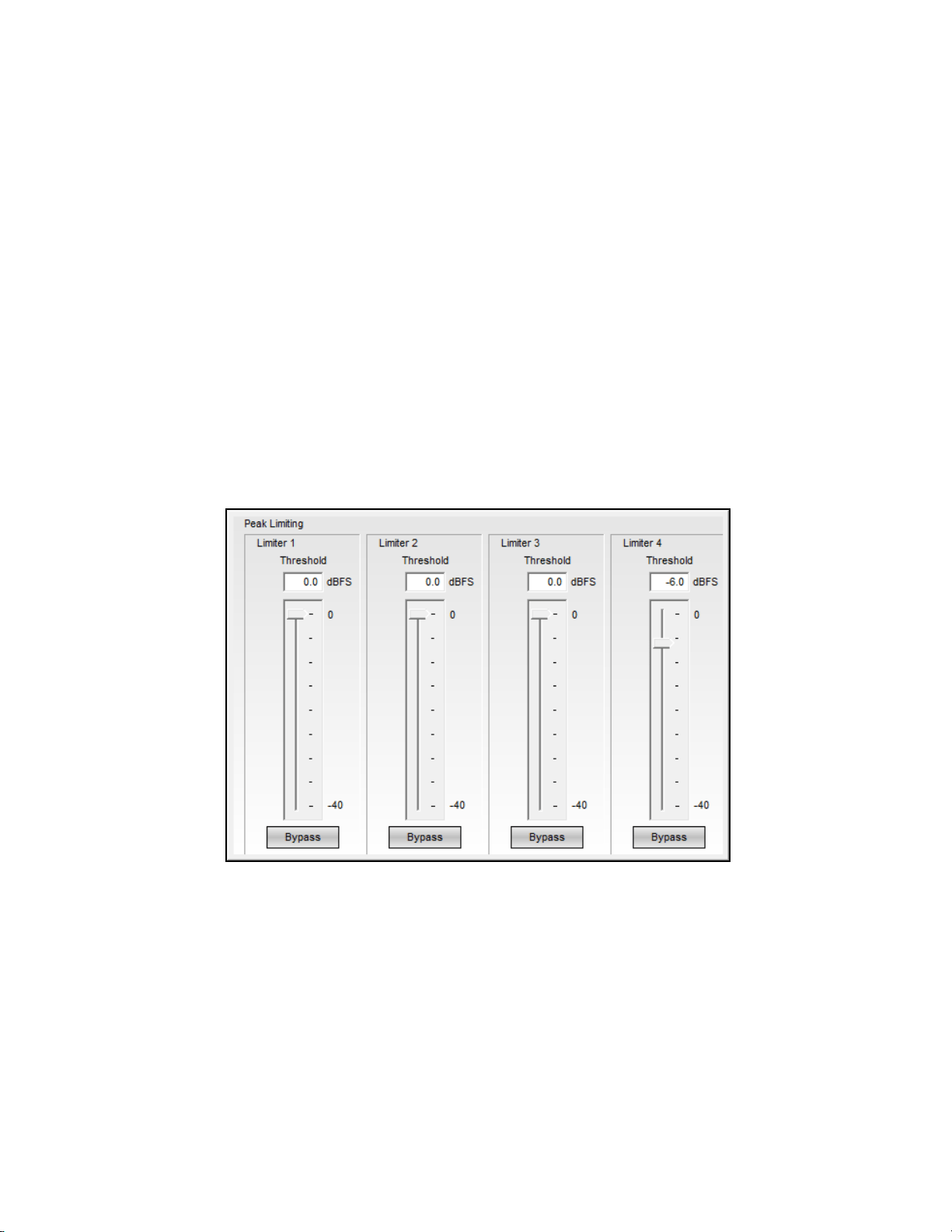
Output Signal Limiter
Each output signal processing stage includes a signal limiter. Selecting any of the
four signal limiter processing blocks will cause the signal limiter control panel to be
displayed.
Fig. 3.9- Output Signal Limiter
Threshold (channel) – Enter the signal level threshold, in dBFS, at which
the output limiter will engage using either a numeric value or by using the
slider control.
Bypass (channel) – Selecting the bypass control will cause the output signal
limiter to be disabled for the selected channel.
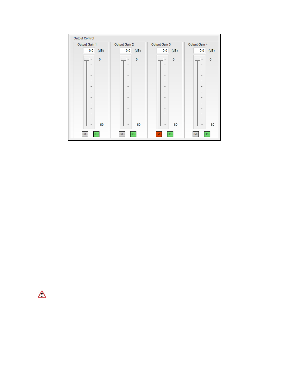
Output Level Control
Each output processing stage includes an output level control. Selecting any of the
four output level controls will cause the output level control panel to be displayed.
Configuring the SP-24 Processor
25
Fig. 3.10- Output Level Control
Output Level (channel) – Enter the output signal level attenuation, in dB,
using either a numeric value or by using the slider control.
Mute (channel) – Select the Mute control to mute the output channel.
Polarity (channel) – Select the Polarity to invert the signal polarity of the
output channel. Green indicates normal, 0° phase, while red indicates the
signal polarity is inverted, 180° phase.
Working with Scenes
Working with scenes
The ControlSpace SP-24 can store up to four Custom Scenes which may be recalled
from the front panel or the SP-24 Editor software. Scenes are created using the SP-
24 Editor software and are stored within the processor for use during system
operation. Each scene represents a unique configuration of signal processing
parameters which are immediately applied when the scene is recalled.
Creating a new scene
A new scene may be created when working either on or offline. To create a new
scene, select File > New.
When working online, creating a New Scene will reset all parameters within the
SP-24 to their default values.
Saving a Scene to a file
ControlSpace
®
SP-24 Editor Software User's Guide
26
The current parameter settings may be saved as a Scene file (.scn) for future use
when working either on or off-line. To save the current parameters as a Scene file
select File > Save.
Opening a Scene from a file
A scene previously saved to the PC may be opened, re-applied and edited when
working either on or off-line. To open an existing scene file select File > Open.
When working on-line, opening a Scene file will overwrite all parameters within
the SP-24 to the values contained within the Scene file.
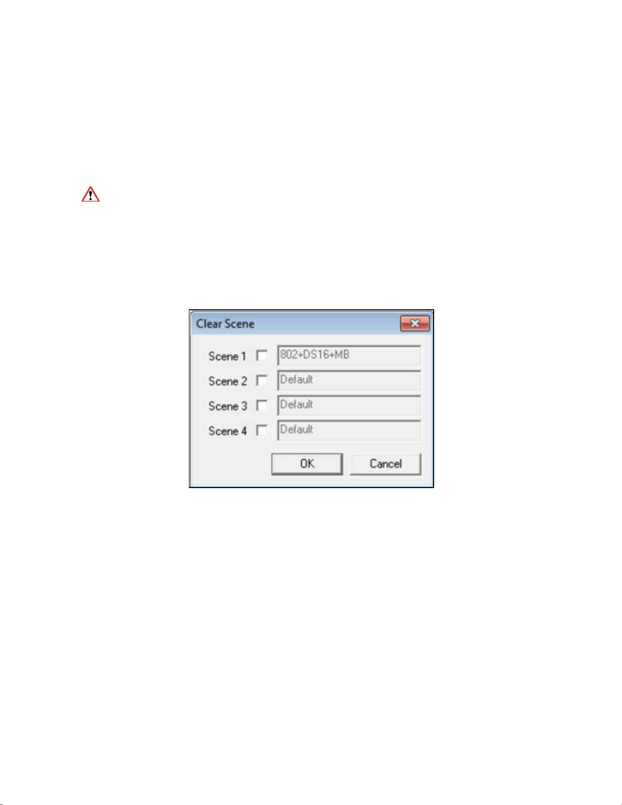
Clear a Scene from the hardware
To clear a Scene from the memory of the SP-24, select the Clear button in the
application tool bar. The Clear Scene dialog is displayed on the screen-
Fig. 4.4- Clear Scene dialog box
Select the Scene to be removed, and click OK to clear the selected scene.
The scene is removed from the SP-24 memory and replaced with a default set of
parameters.
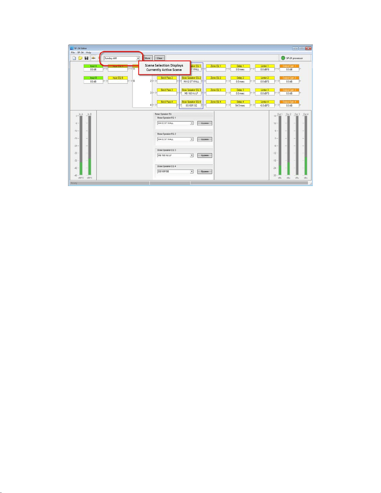
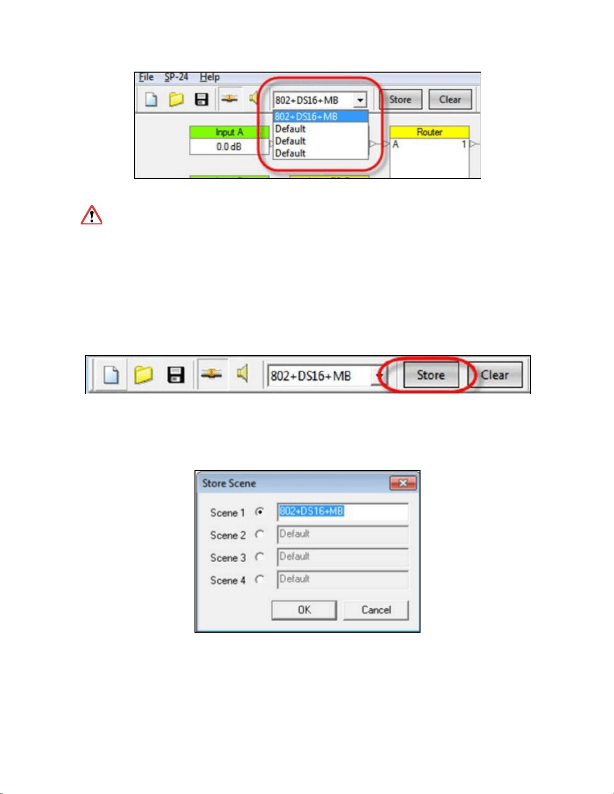
Recall a Scene from the Editor software
Any one of the four Scenes can be invoked from within the Editor software, by
selecting the desired Scene from the Scene drop down menu.
Configuring the SP-24 Processor
27
Fig. 4.3- Scene drop-down list
Once a Scene is recalled, the previous hardware state can only be restored if
it was stored as a Custom Scene. If the front panel was used to configure the
hardware, it is recommended that you save the settings as either a Custom Scene
within the software or as a Scene file on the PC.
Store a Scene to hardware
When working on-line, the current parameter settings may be stored within one of
the four Scene banks within the SP-24 Processor.
Fig. 4.1- The Store button
Once you have selected Store, the Store Scene dialog appears. Select the desired
Scene bank, and provide a name for the Stored Scene.
Fig. 4.2- The Store Scene dialog box
The Scene information is stored within the SP-24 and the Scene is now accessible
from either the front panel or the Scene select drop down within the SP-24 Editor
software.

29
Application Examples
Application examples
The SP-24 sound processor supports four main modes of operation from front panel
interface: Mono, Stereo, Stereo High Pass + Bass and Mono High Pass + Bass.
Each of these configurations determines the state of the router, and allows
selection of the loudspeaker equalization curve for the four outputs.
In some situations other applications may be desired, such as a dual mono
configuration, or the creation of bass arrays using the standard Bose bass array
settings provided in previous Bose loudspeaker controllers. Using the SP-24 Editor
software these additional applications are easily re-created.
Included with the SP-24 Editor software are a number of sample configurations
stored as Custom Scenes. To either view offline or apply one of these sample
Scenes use the following steps:
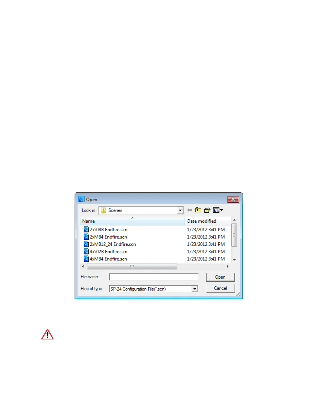
1. Select File>Open.
2. Select the desired sample configuration
Fig. 5.1- File Open dialog
3. The settings for the custom Scene are loaded into the SP-24 Editor
software.
If you are on-line when opening one of the custom Scene files the settings are
immediately applied to the SP-24 processor.
30
ControlSpace
®
SP-24 Editor Software User's Guide
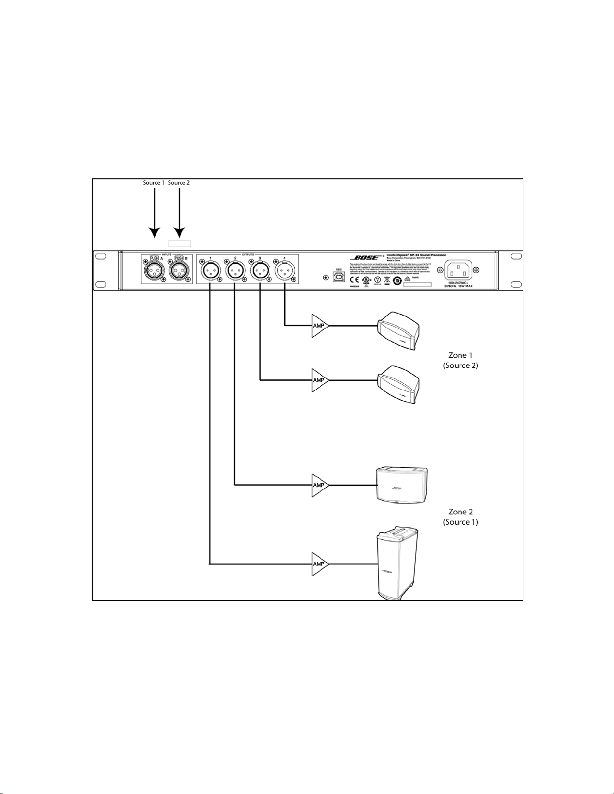
Dual Mono Configuration
In a Dual Mono configuration the processor is configured for two mono audio zones,
each with a unique sources. In addition, each zone may be configured full range of
bi-amped operation. The following illustration shows a typical Dual mono
configuration.
Fig. 5.2- Sample Dual Mono configuration
The sample Dual Mono configuration is configured according to the illustration
above, and the settings implemented in the file are shown below:
31
Application Examples
.
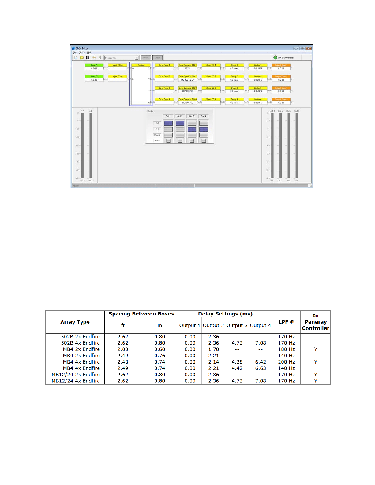
Fig. 5.3- Settings implemented for sample Dual Mono configuration
While not shown above a crossover is implemented on output channel 1 to properly
cross-over the Panaray
®
802
®
-III with the MB4 bass loudspeaker.
Bose Bass Array Configurations
Eight bass array configurations are included with the sample Scene files. The bass
array file you choose to use is determined by the bass loudspeaker you will be
using, the quantity of devices, and the desired low pass frequency. All of the
configurations provided are for endfire bass arrays with mono operation. The
following table summarizes the settings, and recommended center to center cabinet
spacing for the various bass arrays:
Fig. 5.4- Summary of bass array settings
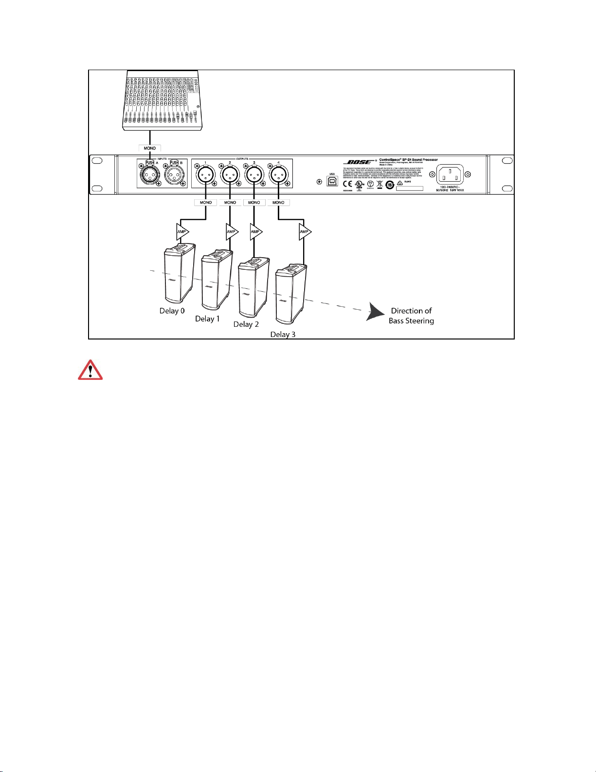
The following image depicts the proper set up and wiring of a 4 bass Endfire bass
array:
32
ControlSpace
®
SP-24 Editor Software User's Guide
Fig. 5.5- Wiring configuration for an Endfire bass array
When working with bass arrays the audio signal for all bass devices must be
processed by the same controller, regardless of whether any signal delay is used.
33
Maintenance
Upgrading SP-24 Firmware
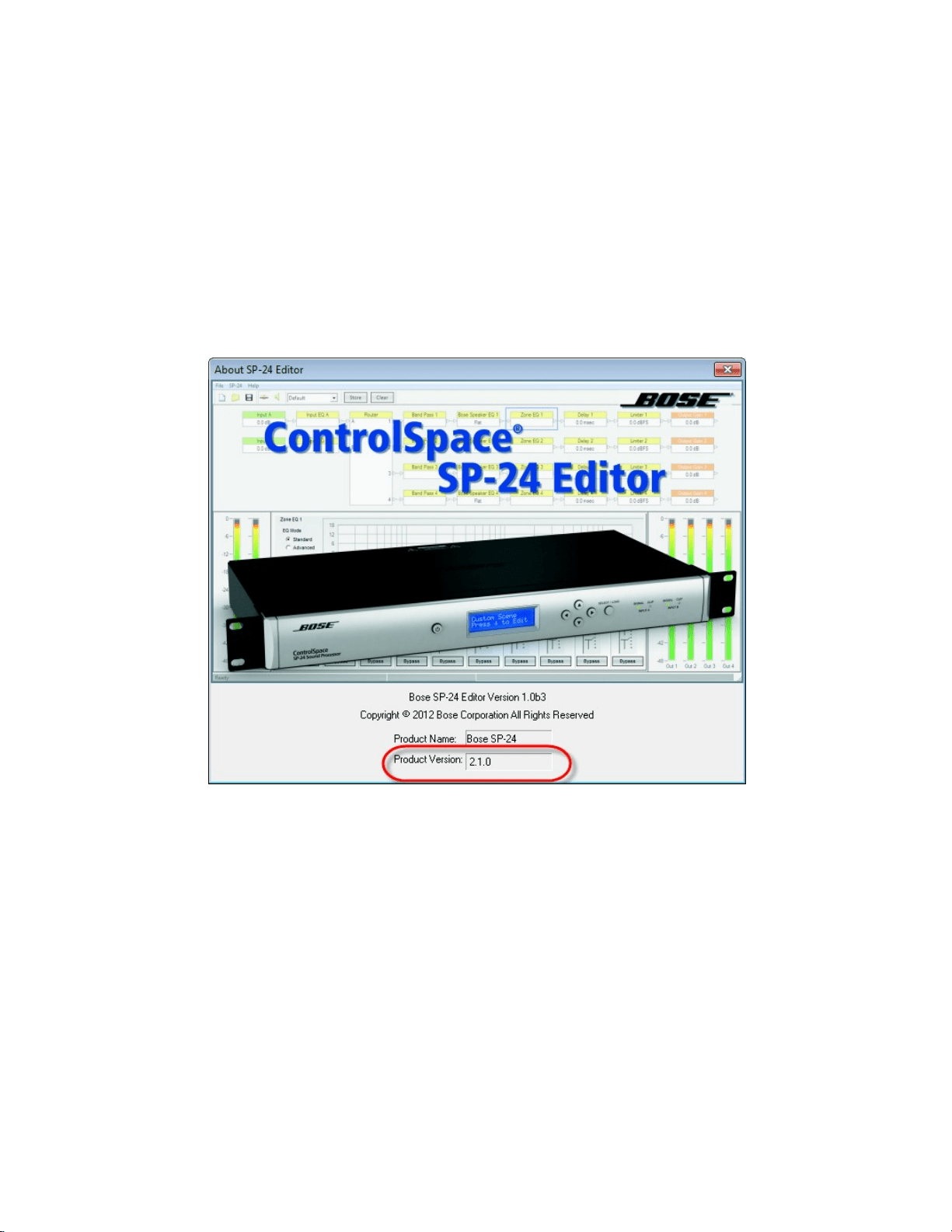
Firmware updates for the SP-24 sound processor are performed using the SP-24
Editor software. The latest firmware version is always available at pro.Bose.com,
and, when connected to the processor via USB, the current firmware version you
are using can be determined by selecting Help> About Bose SP-24 Editor..
Fig. 6.1- About SP-24 Editor Dialog, firmware version is shown in lower section
All loudspeaker database and firmware updates are provided using an application
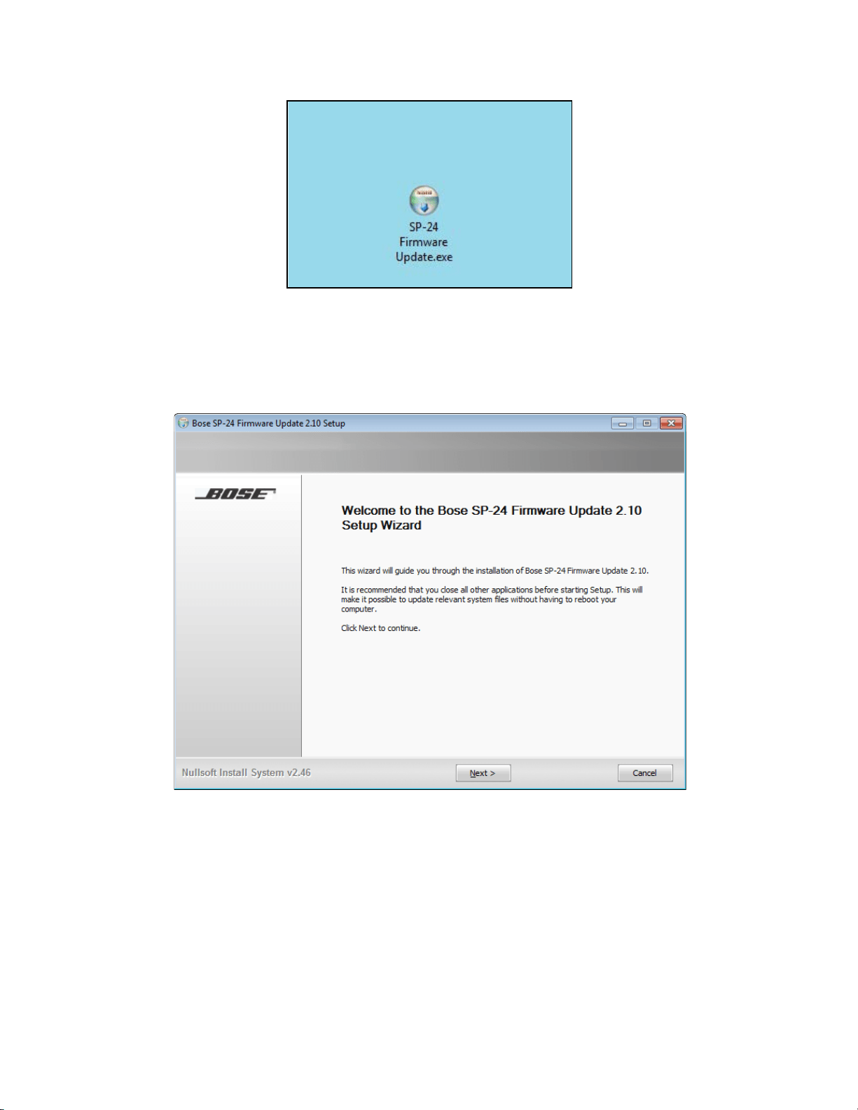
update installer. To install the necessary files run the update installer.
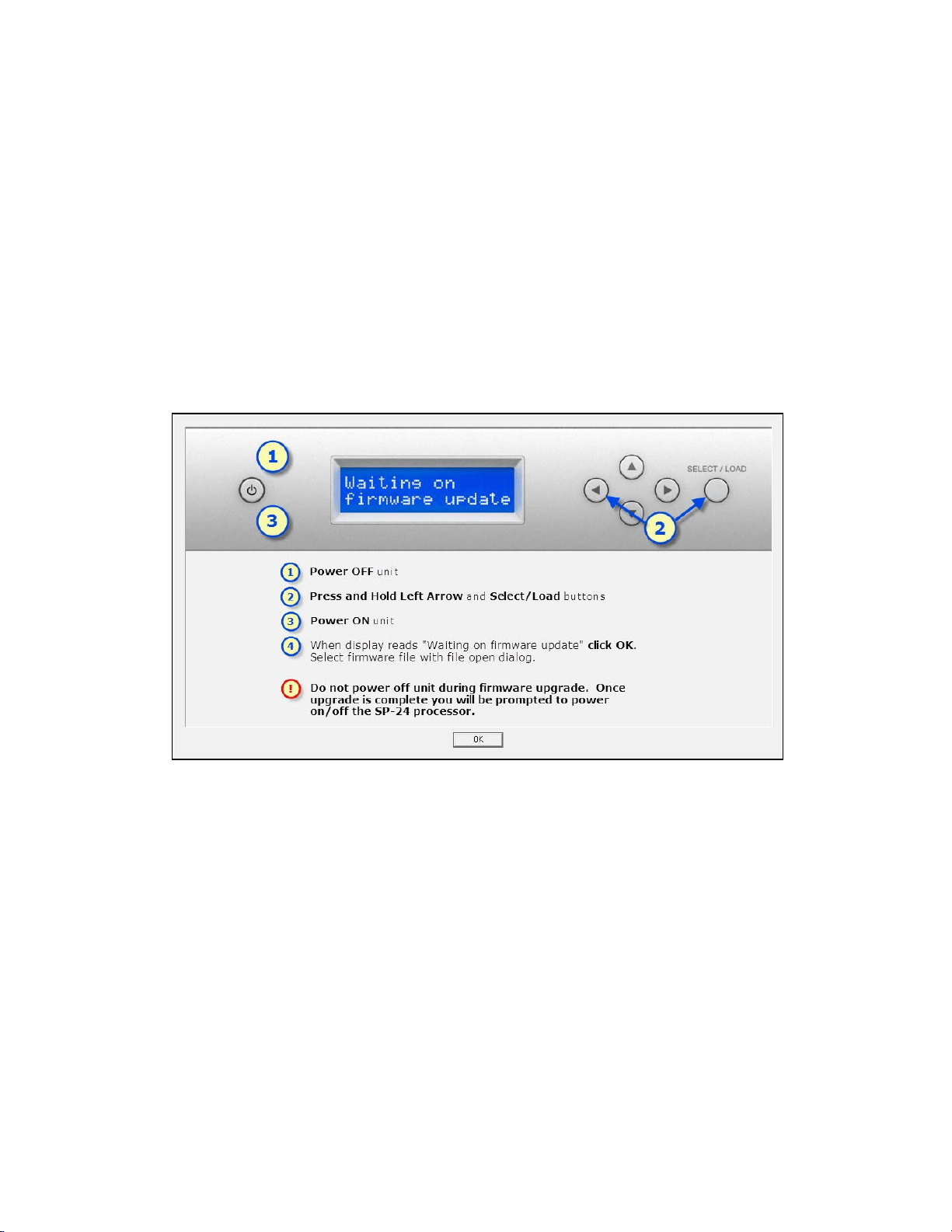
1. Download the application update installer to your PC and run SP-24
Firmware Update application.
ControlSpace
®
SP-24 Editor Software User's Guide
34
Fig. 6.2- SP-24 Firmware Update Application
2. Launch the SP-24 Firmware update application and follow the on-screen
steps to install the updated SP-24 firmware and/or loudspeaker database
update:
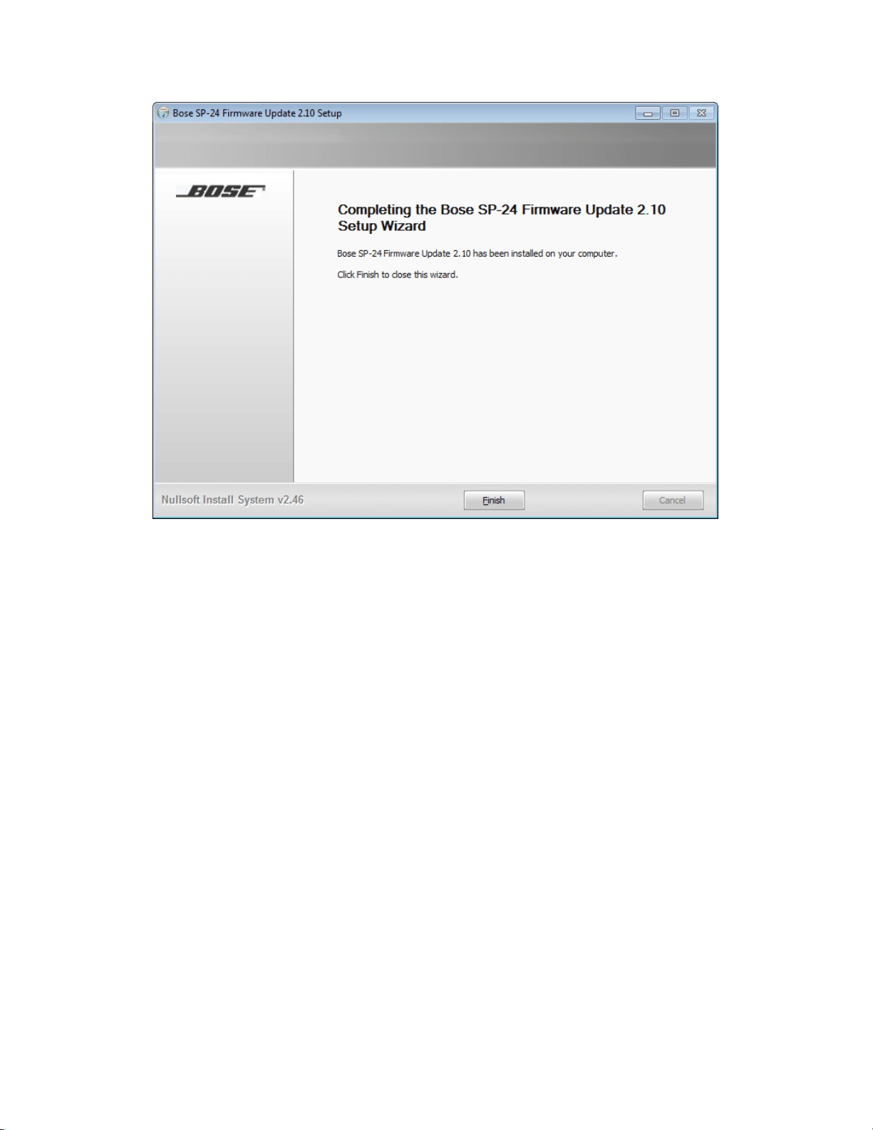
Fig. 6.3- SP-24 Firmware Update Installation Dialog
3. Once the installation is complete, click ‘Finish’ to close the installer.
Maintenance
35
Fig. 6.4- SP-24 Firmware Update Installation Dialog
You are now ready to upgrade the firmware within the SP-24 sound processor. Use
the following procedure to install the new firmware:
1. Make sure the SP-24 sound processor is connected to the PC and powered
on.
2. Launch the SP-24 Editor software, and establish a connection between the
PC and the hardware.
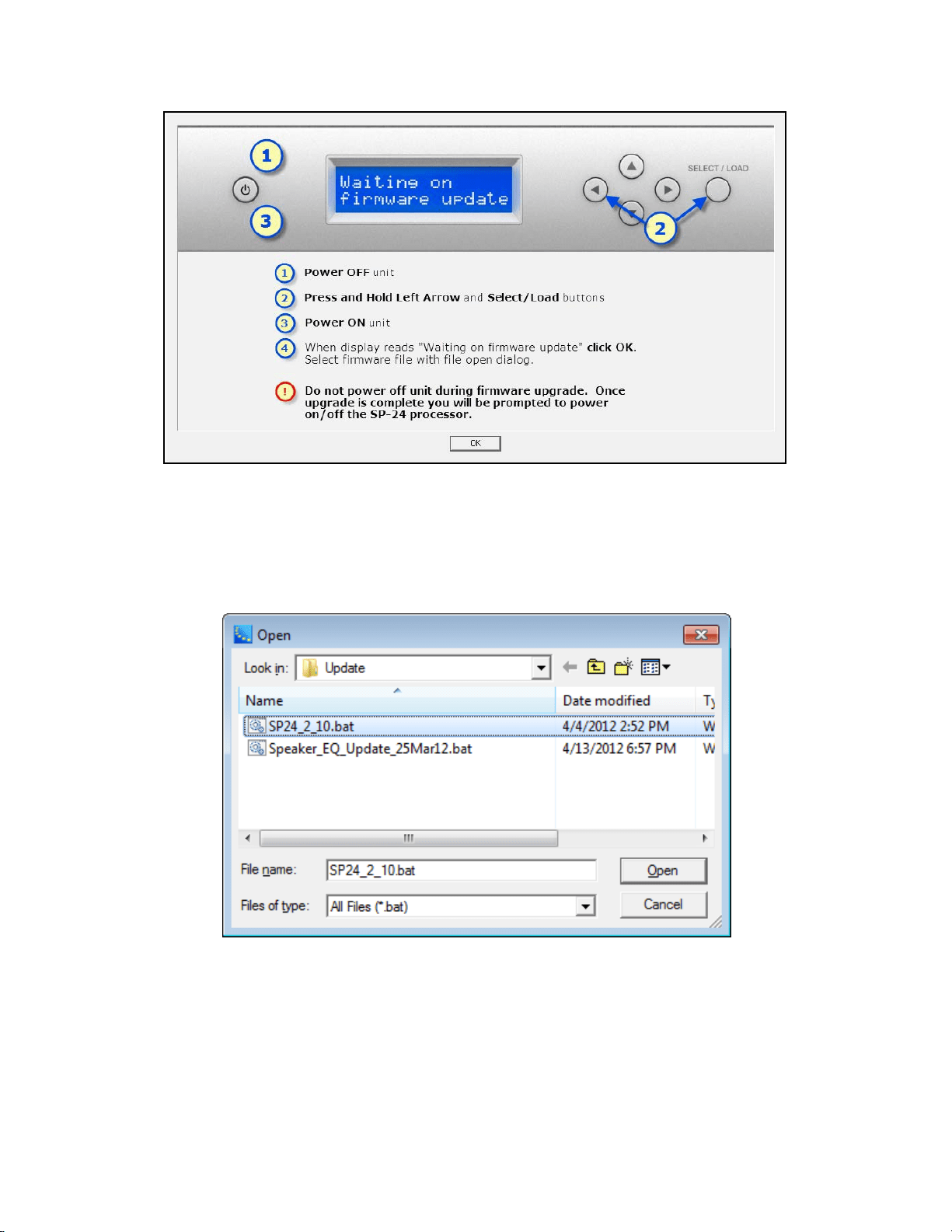
3. The Firmware update dialog contains the necessary instructions for placing
the SP-24 sound processor into firmware update mode. Follow the
instructions, and press ‘OK’.
ControlSpace
®
SP-24 Editor Software User's Guide
36
Fig. 6.5- SP-24 Editor firmware update instruction dialog
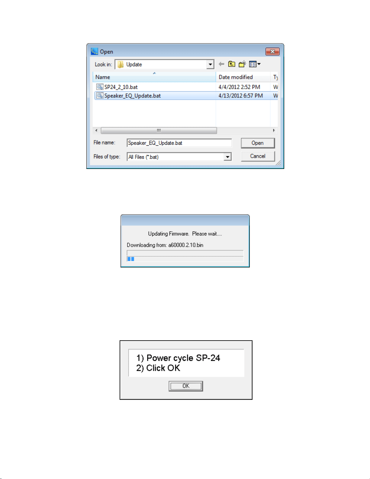
4. Pressing 'OK' causes the File Open dialog to appear. Select the new
firmware file that will be uploaded to the processor.
Fig. 6.6- SP-24 firmware file selection
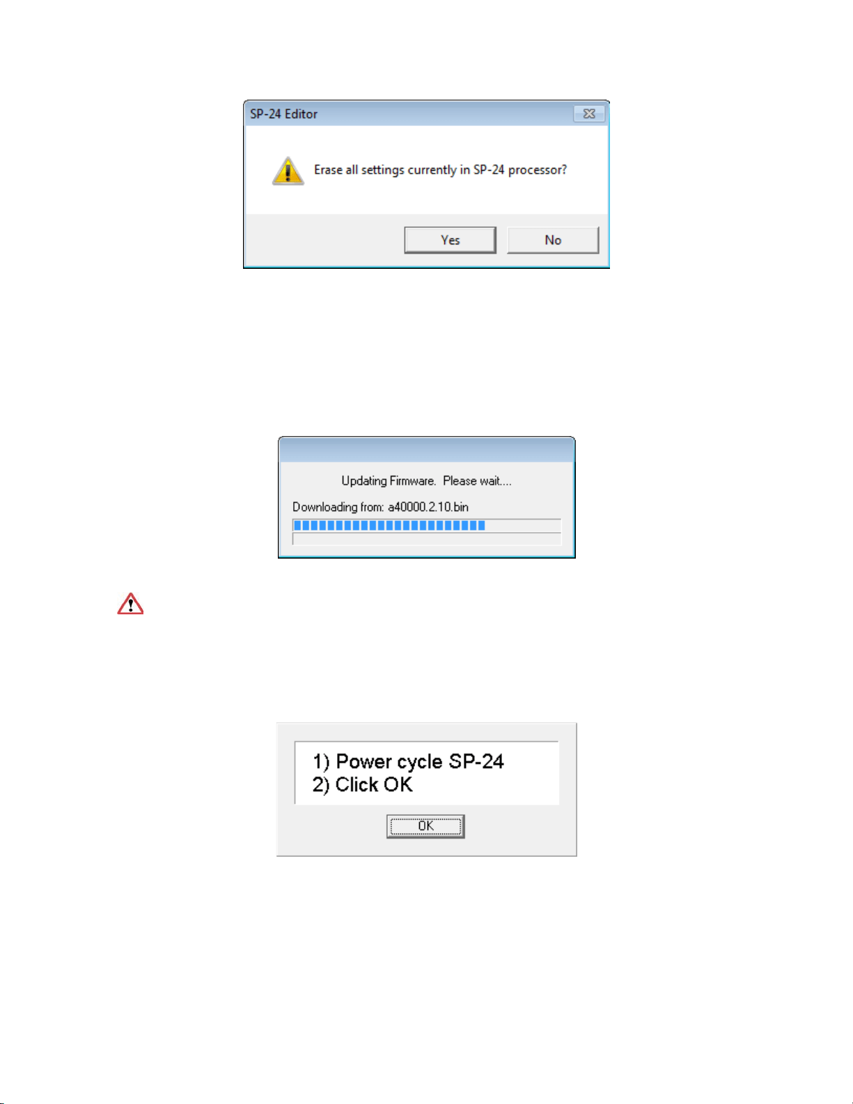
5. You will be prompted to Erase all settings from the processor.
Maintenance
37
Fig. 6.7- Erase all settings confirmation
6. Selecting Yes will remove the current configuration, and all Custom Scenes
from the processor, selecting No will leave the current configuration and
Custom Scenes untouched.
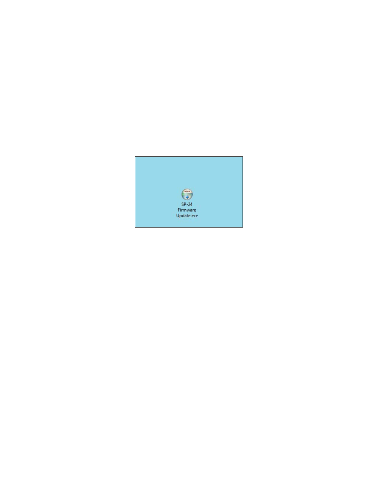
7. Once the firmware update process has begun the firmware update progress
dialog appears.
Fig. 6.8- Firmware update progress dialog
During the firmware update procedure do not disconnect the unit from the
PC, or power cycle the SP-24 sound processor, until you are prompted to do so.
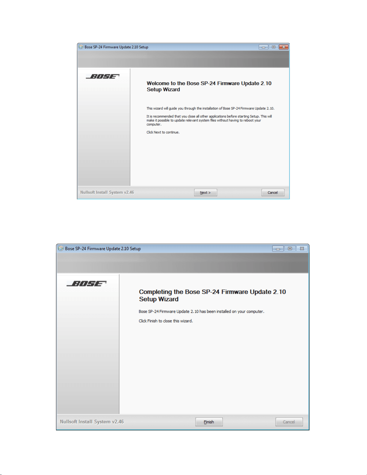
8. You will be prompted to power cycle the SP-24 sound processor. Once the
SP-24 sound processor has rebooted press OK to restore the connection
between the SP-24 Editor software and the hardware.
Fig. 6.9- Firmware update complete dialog
ControlSpace
®
SP-24 Editor Software User's Guide
38
Upgrading the Bose Loudspeaker EQ Database within the
SP-24 Sound Processor
As new loudspeaker products become available from Bose professional systems we
will issue a loudspeaker database only firmware update. The most recent
loudspeaker EQ database update for the SP-24 sound processor is always available
at pro.Bose.com.
All loudspeaker database and firmware updates are provided using an application
update installer. To install the necessary files run the update installer.
1. Download the application update installer to your PC and run SP-24
Firmware Update application.
Fig. 6.10- SP-24 Firmware Update Application
2. Launch the SP-24 Firmware update application and follow the on-screen
steps to install the updated SP-24 firmware and/or loudspeaker database
update:
Maintenance
39
Fig. 6.11- SP-24 Firmware Update Installation Dialog
3. Once the installation is complete, click Finish to close the installer.
ControlSpace
®
SP-24 Editor Software User's Guide
40
Fig. 6.12- SP-24 Firmware Update Installation Dialog
You are now ready to update the loudspeaker EQ database within the SP-24 sound
processor. Use the following process to update the SP-24 loudspeaker EQ
database:
1. Make sure the SP-24 sound processor is connected to the PC and powered
on.
2. Launch the SP-24 Editor software, and establish a connection between the
PC and the hardware.
3. The Firmware update dialog contains the necessary instructions for placing
the SP-24 sound processor into firmware update mode. Follow the
instructions, and press ‘OK’.
Fig. 6.13- SP-24 Editor firmware update instruction dialog
4. Pressing OK causes the File Open dialog to appear. Select the new
loudspeaker EQ database file that will be uploaded to the processor.
Maintenance
41
Fig. 6.14- Loudspeaker EQ update selection
5. Once the firmware update process has begun the firmware update progress
dialog appears.
Fig. 6.15- Firmware update progress dialog
During the firmware update procedure do not disconnect the unit from the PC, or
power cycle the SP-24 sound processor, until you are prompted to do so.
6. You will be prompted to power cycle the SP-24 sound processor. Once the
SP-24 sound processor has rebooted press OK to restore the connection
between the SP-24 Editor software and the hardware.
Fig. 6.16- Firmware update complete dialog

ControlSpace
®
SP-24 Editor Software User's Guide
42
Upgrading an Existing System to the SP-24 Sound
Processor
In some situations you may wish to upgrade an existing system using an older
Panaray® system controller to the SP-24 sound processor. In this situation it is
recommend that the SP-24 Editor is used to configure the processor for operation.
Within the Bose Speaker EQ processing block you may select the required active
equalization curve for a variety of discontinued Bose loudspeaker products. The
following legacy equalization curves are available:
BOSE Professional Legacy Equalization Curves
FreeSpace
®
Products
Panaray
®
Products
LT Products
FS1B 100Hz LP
Acoustic Wave
®
Cannon (AWCS)
LT3202-I
FS1B Surface
402-I
LT4402-I
FS1B Flush
802-II
LT9702-I
FS360 Hard
802-II ST
LT3202-I Cluster
FS360 Soft
AWCS
LT4402-I Cluster
FS360 Deck
502BEX
LT9702-I Cluster
Model 8
Model 32