Loading ...
Loading ...
Loading ...
Overview
12 • English EX-440C/1280/1280C/12AEC • Installation & Operation Guide
PRO.BOSE.COM
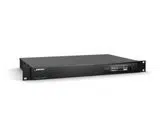
EX-440C
Front Panel
q Power/Status indicator: This LED illuminates white when the processor is powered on. The LED may blink
white or change colors while the system is booting up. If the LED illuminates and remains red after the
bootup is complete, please see Maintenance > Troubleshooting (page 26).
w OLED Display: This display provides metering and network information and settings. See Operation
(page 20) for more information.
e Rotary/Press Knob: Turn and press this knob to navigate menus. See Operation (page 20) for more
information.
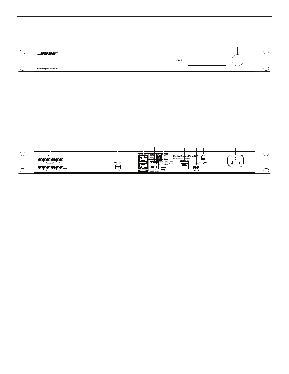
Rear Panel
q Analog audio inputs: 4 balanced audio inputs (3.81 mm, 6-pin Euroblock), routable to automatic echo
cancellation (AEC) using ControlSpace Designer software. See Installation > 3. Analog Audio Connections
(page 16) for more information.
w Analog audio outputs: 4 balanced audio outputs (3.81 mm, 6-pin Euroblock). See Installation >
3. Analog Audio Connections (page 16) for more information.
e Control Inputs: 2 inputs for general-purpose control (3.81 mm, 6-pin Euroblock). See Installation >
7. Control Connections > GPIO > General-purpose Inputs (page 18) for more information.
r Dante ports: 2 Ethernet ports for connection of Dante digital audio devices. See Installation >
4. Dante Network Connection (page 17) for more information.
t VoIP port: RJ-45 port for communication via Voice-over-Internet-Protocol (SIP 2.0-compliant).
See Installation > 6. Far-end Connections > VoIP (page 17) for more information.
y Micro-B USB port: Connect this port to a computer for use with soft codecs with stereo input and output.
See Installation > 6. Far-end Connections > Soft Codecs (page 17) for more information.
u AmpLink Out port: RJ-45 connection for use with AmpLink-equipped amplifiers. See Installation >
4. AmpLink Connection (page 16) for more information.
i Serial port: 3-wire RS-232C (DTE) connection (3.81 mm, 3-pin Euroblock) to serial control interface.
See Installation > 7. Control Connections > Serial (page 19) for more information.
o Telephone Line port: RJ-11 connection for analog telephone line. See Installation > 6. Far-end Connections
> Telephone (page 17) for more information.
a Power input: Power cord connection to AC mains power (IEC 60320-C14 inlet). See Installation >
8. Power Connection (page 19) for more information.
y u aoitrq ew
q ew
Loading ...
Loading ...
Loading ...