
Loading ...
Attach Ground Stack Bracket to ShowMatch Array Frame
To attach the ground stack bracket to the ShowMatch Array Frame, follow
these instructions:
1. Attach the leveling feet to the bottom of the frame. See Fig. 6. Fully
tighten each screw to ensure the feet are level.
2. Align the ground stack bracket with the holes along the center rail as
indicated. The front ground stack hole should be placed at Location D.
3. Attach the ground stack using the bolts and nuts from the array frame.
4. Use the included safety pins to ensure security of the bolts.
5. Connect the front two rigging locations of the first (bottom) full-range
module to the two front rigging locations on the frame. Then connect the
back of the module to the ground stack bracket.
Attach Ground Stack Bracket to ShowMatch SMS118
To attach the ground stack bracket directly to the ShowMatch SMS118
subwoofer, follow these instructions:
1. Remove the 4 screws that attach the frame bracket to the base of
the ground stack bracket. See Fig. 4.
2. Separate the ground stack bracket from the frame bracket. The base
of the ground stack bracket should now be flat.
3. Remove the 4 screws connecting the pole mount to the top of the
subwoofer. Do not remove the actual pole mount. See Fig. 5.
4. Attach the ground stack bracket to the subwoofer using the screws
removed from the pole mount.
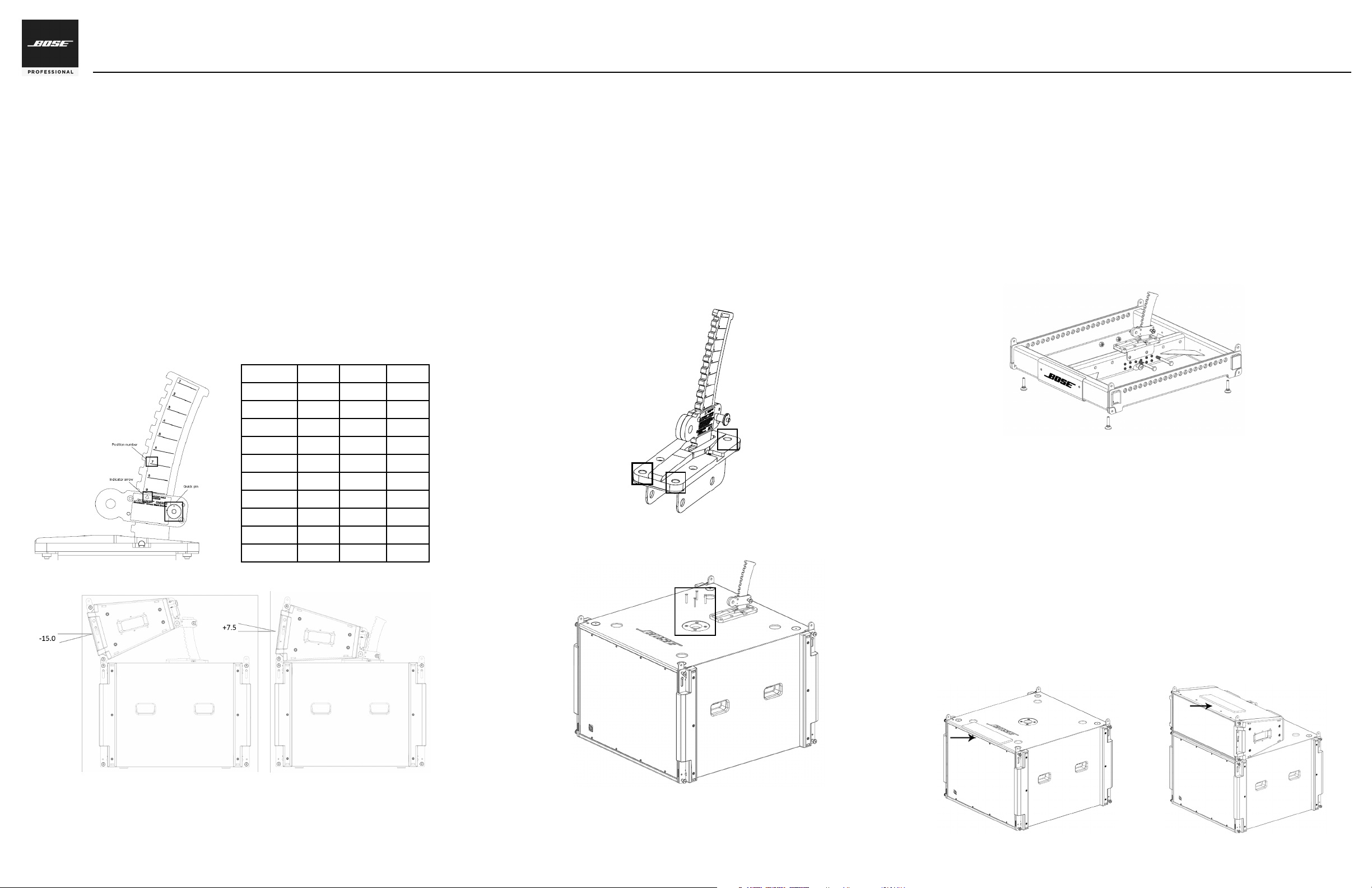
Adjust Ground Stack Bracket Angle
Adjust the ground stack bracket before installation of the first full-range
module to control the pitch angle of the array. The range of pitch angles
depends on the first full-range module in the stack.
To adjust the ground stack bracket angle, follow these instructions:
1. Remove the quick pin from the ground stack bracket.
2. Position the top of the adjustable link directly under the line that
corresponds to the desired position. The indicator arrow on the
adjustable link points to the position number. See Fig. 1. Refer to the
table in Fig. 2 for the corresponding pitch angle for each full-range
module.
3. Replace the quick pin to lock the adjustable link in place.
Note: A negative angle measurement indicates that the module is aimed
down. A positive angle measurement indicates that the module is aimed up.
See Fig. 3.
ShowMatch
TM
DeltaQ
TM
Array Loudspeaker
Ground Stack Bracket Accessory: SMGSB
Position SM5 SM10 SM20
1 -22.5° -20° -15°
2 -20° -17.5° -12.5°
3 -17.5° -15° -10°
4 -15° -12.5° -7.5°
5 -12.5° -10° -5°
6 -10° -7.5° -2.5°
7 -7.5° -5° 0°
8 -5° -2.5° 2.5°
9 -2.5° 0° 5°
10 -0° 2.5° 7.5°
Fig. 2. Pitch angle by position and module
Fig. 3. Negative and positive angle measurements
Fig. 1. Position number
Fig. 4. Remove screws from bracket
Fig 5. Remove pole mount screws
Fig. 6. Ground stack bracket on array frame
Using the Isolation Pads
To prevent vibration in ground stacks built on ShowMatch SMS118
subwoofers, use the enclosed isolation pads. Remove paper backing to
expose adhesive side of pad.
To ax the isolation pads, follow these instructions:
1. Align edge of pad with front edge of subwoofer. Ax isolation pad to
top surface of subwoofer, adhesive side down. See Fig. 7.
2. Install next module of ground stack. For more information, see the
ShowMatch DeltaQ Array Loudspeakers Installation and Safety
Guidelines, available at pro.Bose.com.
3. Position pad over Bose logo on top surface of full-range module. Ax
isolation pad adhesive side down. See Fig. 8.
4. Repeat steps 2-3 until ground stack is complete.
Fig. 7. Ax isolation pad to subwoofer
Fig. 8. Ax isolation pad to full-range module