Loading ...
Loading ...
Loading ...
Page 12
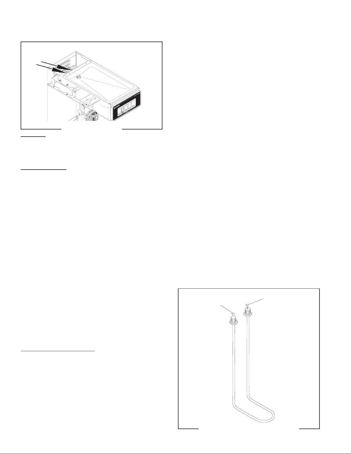
TANK HEATER
Location:
The tank heater is located inside the tank and
secured to the tank lid.
Test Procedures:
1. Disconnect the brewer from the power supply.
2. With a voltmeter, check the voltage across the
black and red wire. Connect the brew to the power
source. The indication must be 220 to 240 volts
ac.
3. Disconnect the brewer from the power source.
If voltage is present as described, proceed to #4
If voltage is not present as described, refer to the
Wiring Diagrams
and check wiring harness.
4. Disconnect the thermal cut-offs from the tank
heater terminals.
5. Check for continuity across the tank heater termi-
nals.
If continuity is present as described, reconnect the
thermal cut-offs, the tank heater is operating properly.
If continuity is not present as described, replace the
tank heater.
NOTE- If the tank heater remains unable to heat,
remove and inspect heater for cracks in the sheath.
Removal and Replacement:
1. Remove the tank inlet fitting securing the fill basin
to the tank lid, remove fill basin and tank inlet
gasket. Set all three parts aside for reassembly.
2. Disconnect the thermal cut-off with blanket warmer
lead (white) and thermal cut-off with ready light
harness lead (black) from the tank heater termi-
nals.
3. Remove the thermostat capillary bulb by firmly
pulling up on the capillary at the tank lid. This will
disengage the grommet from the tank lid.
P1262
FIG. 6 TANK HEATER
SERVICE (cont.)
10860.1 071598
4. Remove sprayhead and the hex nut securing the
sprayhead tube to the hood. Set aside for reas-
sembly.
5. Remove the eight #8-32 nuts securing the tank lid
to the tank.
6. Remove the tank lid with sprayhead tube and tank
heater.
7 Remove the two hex nuts securing the tank heater
to the tank lid. Remove tank heater with gaskets
and discard.
8. Install new tank heater with gaskets on the tank lid
and secure with two hex nuts.
9. Install tank lid with sprayhead tube and tank heater
using eight #8-32 hex nut.
10. Secure sprayhead tube to hood using a hex nut.
11. Install sprayhead.
12. Reconnect the thermal cut-offs to the tank heater
terminals.
13. Slide the grommet to the line 4.5" above the
capillary bulb.
14. Insert the capillary bulb through the hole in the
tank lid and press the grommet firmly and evenly
so that the groove in the grommet fits into the tank
lid.
15. Carefully bend the capillary tube so that the tube
and bulb inside the tank are in the vertical position.
NOTE - The capillary tube must be clear of any electri-
cal termination and not kinked.
16. Install fill basin, secure with tank inlet fitting and
gasket.
17. Refer to Fig.7 when reconnecting the tank heater
wires.
FIG. 7 TANK HEATER TERMINALS
P1163
Thermal Cut-Off & BLK
Lead on Ready Light
Harness
Thermal Cut-Off & WHI
Lead from Tank
Warmer Blanket
Loading ...
Loading ...
Loading ...