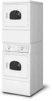
Installation/Operation
Clothes Dryer
Electric and Gas Models
DRY722C_SVG
Original Instructions
Keep These Instructions for Future Reference.
CAUTION: Read the instructions before using the machine.
(If this machine changes ownership, this manual must accompany machine.)
www.alliancelaundry.com
Part No. D516906ENR1
October 2018

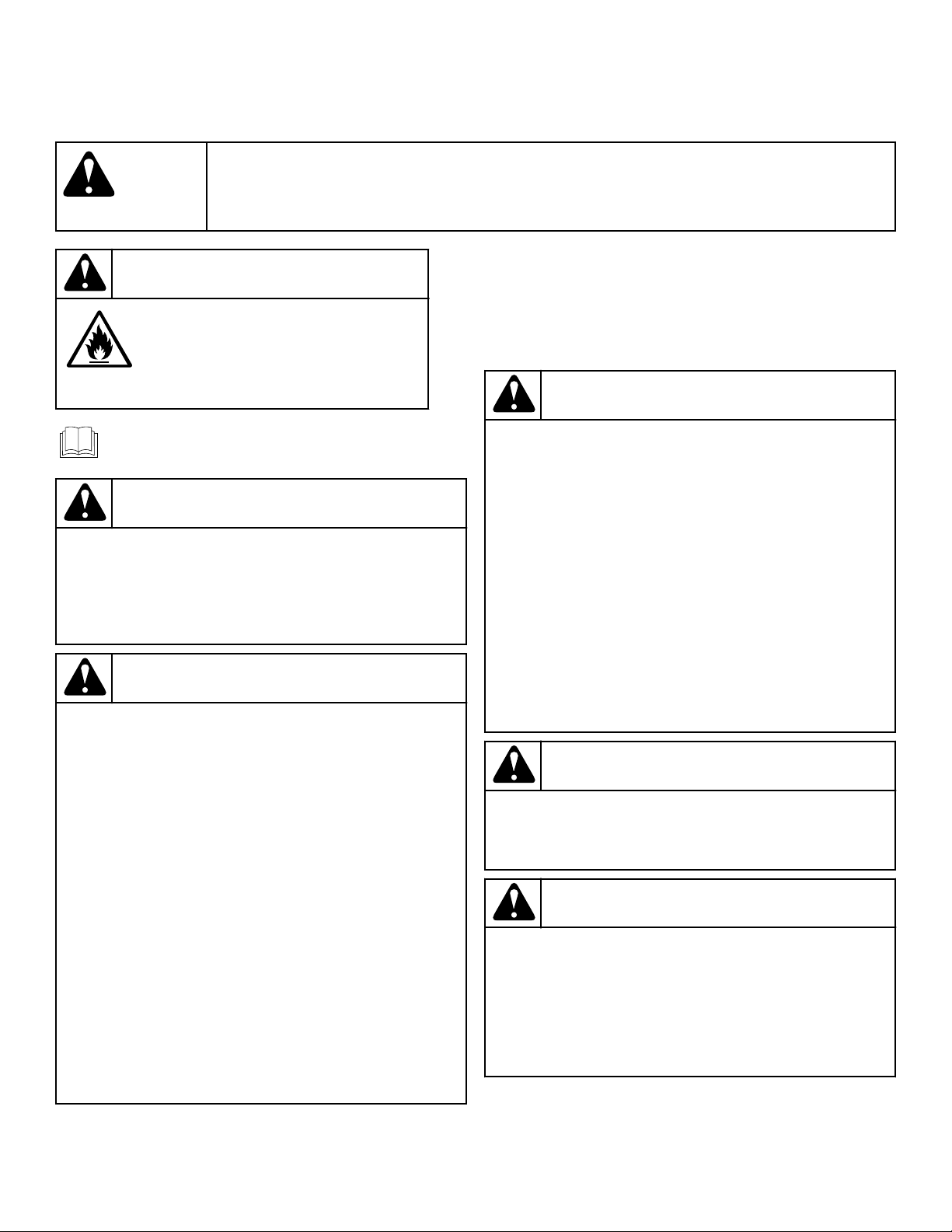
WARNING
WARNING
Risk of fire. Highly flammable material.
W881
Read all instructions before using unit.
WARNING
FOR YOUR SAFETY, the information in this manual
must be followed to minimize the risk of fire or ex-
plosion or to prevent property damage, personal in-
jury or death.
W033
WARNING
• Do not store or use gasoline or other flammable
vapors and liquids in the vicinity of this or any
other appliance.
•
WHA
T T
O DO IF YOU SMELL GAS:
•
Do not try to light any appliance.
•
Do not touch any electrical switch; do not use
any phone in your building.
•
Clear the room, building or area of all occu-
pants.
•
Immediately call your gas supplier from a
neighbor
’
s phone. Follow the gas supplier
’
s in-
structions.
• If you cannot reach your gas supplier, call the
fire department.
• Installation and service must be performed by a
qualified installer, service agency or the gas sup-
plier.
W052
IMPORTANT: Purchaser must consult the local gas
supplier for suggested instructions to be followed if
the dryer user smells gas. The gas utility instructions
plus the SAFETY and WARNING note directly above
must be posted in a prominent location near the dryer
for customer use.
WARNING
• Installation of unit must be performed by a quali-
fied installer
.
• Install clothes dryer according to manufacturer’s
instructions and local codes.
• DO NOT install a clothes dryer with flexible plas-
tic venting materials. If flexible metal (foil type)
duct is installed, it must be of a specific type
identified by the appliance manufacturer as suita-
ble for use with clothes dryers. Refer to section
on connecting exhaust system. Flexible venting
materials are known to collapse, be easily crush-
ed, and trap lint. These conditions will obstruct
clothes dryer airflow and increase the risk of fire.
W729R1
WARNING
To reduce the risk of severe injury or death, follow all
installation instructions. Save these instructions.
W894
WARNING
FOR YOUR SAFETY
Do not store or use gasoline or other flammable va-
pors and liquids in the vicinity of this or any other
appliance.
W053
This product uses FreeRTOS V7.2.0 (www.freertos.org).
©
Copyright, Alliance Laundry Systems LLC -
DO NOT COPY or TRANSMIT
3
Part No. D516906ENR1

The following information applies to the state of Massachusetts,
USA.
• This appliance can only be installed by a Massachusetts li-
censed plumber or gas fitter.
• This appliance must be installed with a 36 inch [910 mm]
long flexible gas connector.
• A “T-Handle” type gas shut-of
f valve must be installed in the
gas supply line to this appliance.
• This appliance must not be installed in a bedroom or bath-
room.
©
Copyright, Alliance Laundry Systems LLC -
DO NOT COPY or TRANSMIT
4
Part No. D516906ENR1

Table of Contents
...............................................................................................................3
Safety Information..................................................................................7
Explanation of Safety Messages....................................................................... 7
Important Safety Instructions........................................................................... 7
Dimensions............................................................................................. 9
Installation........................................................................................... 12
Before You Start........................................................................................... 12
Supplies....................................................................................................12
Additional Security....................................................................................12
Position and Level the Dryer..........................................................................12
Connect Dryer Exhaust System...................................................................... 14
Exhaust Direction......................................................................................15
Exhaust System.........................................................................................15
Multi-Dryer Installation Exhaust Requirements............................................16
Gas Dryers - Connect Gas Supply Pipe........................................................... 19
Electric Dryer Only - Connect Electrical Plug..................................................21
Earth/Ground Information.......................................................................... 21
Connecting Power Cord with Three-Wire Plug.............................................23
Connecting Power Cord with Four-Wire Plug.............................................. 25
Reverse Door, if Desired................................................................................26
Wipe Out Inside of Dryer...............................................................................28
Plug In the Dryer
.......................................................................................... 28
Electric Dryer........................................................................................... 28
Gas Dryer................................................................................................. 28
Recheck Steps.............................................................................................. 30
Check Heat Source........................................................................................30
Electric Dryers.......................................................................................... 30
Gas Dryers
................................................................................................30
V
ending................................................................................................ 32
Coin Slide Guards.........................................................................................32
Coin Slide Control........................................................................................ 32
Setting Dry Time Dipswitches........................................................................32
Dipswitch Settings........................................................................................ 34
Test Setting.................................................................................................. 36
Slide Extension Assembly............................................................................. 36
Installing Coin Slide Assembly Into Meter Case: Option One........................ 37
Installing Coin Slide Assembly Into Meter Case: Option Two........................38
©
Copyright 2018, Alliance Laundry Systems LLC
All rights reserved. No part of the contents of this book may be reproduced or transmitted in any form or by any means without the expressed
written consent of the publisher.
©
Copyright, Alliance Laundry Systems LLC -
DO NOT COPY or TRANSMIT
5
Part No. D516906ENR1

Operation............................................................................................. 39
Operation Instructions for Nonmetered and Coin Slide Dryers.......................... 39
Clean Lint Filter........................................................................................39
Load Laundry........................................................................................... 39
Close Loading Door...................................................................................39
Determine Proper Dryer.............................................................................39
Set Fabric Selector.....................................................................................39
Start Dryer................................................................................................40
Operation Instructions for MDC Dryers.......................................................... 40
Clean Lint Filter........................................................................................40
Load Laundry........................................................................................... 40
Close Loading Door...................................................................................41
Determine Proper Dryer.............................................................................41
Set Fabric Selector.....................................................................................41
Insert Coins or Card...................................................................................41
Start Dryer................................................................................................42
Indicator Lights.........................................................................................42
Maintenance......................................................................................... 43
Lubrication...................................................................................................43
Care of Y
our Dryer........................................................................................43
Dryer Interior............................................................................................43
Cabinet.....................................................................................................43
Control Panel............................................................................................ 43
Exhaust System.........................................................................................43
Lint Filter.....................................................................................................43
Motor Overload Protector.............................................................................. 44
For Energy Conservation............................................................................... 44
Troubleshooting....................................................................................45
Contact Information............................................................................. 47
Installer Checklist.................................................................................48
©
Copyright, Alliance Laundry Systems LLC -
DO NOT COPY or TRANSMIT
6
Part No. D516906ENR1
Safety Information
Explanation of Safety Messages
Precautionary statements (“DANGER,” “WARNING,” and
“CAUTION”), followed by specific instructions, are found in this
manual and on machine decals. These precautions are intended
for the personal safety of the operator, user, servicer, and those
maintaining the machine.
DANGER
Indicates an imminently hazardous situation that, if
not avoided, will cause severe personal injury or
death.
WARNING
Indicates a hazardous situation that, if not avoided,
could cause severe personal injury or death.
CAUTION
Indicates a hazardous situation that, if not avoided,
may cause minor or moderate personal injury or
property damage.
Additional precautionary statements (“IMPORTANT” and
“NOTE”) are followed by specific instructions.
IMPORTANT: The word “IMPORTANT” is used to in-
form the reader of specific procedures where minor
machine damage will occur if the procedure is not fol-
lowed.
NOTE: The word “NOTE” is used to communicate in-
stallation, operation, maintenance or servicing informa-
tion that is important but not hazard related.
Important Safety Instructions
Save These Instructions
WARNING
To reduce the risk of fire, electric shock, serious in-
jury or death to persons when using your dryer
, fol-
low these basic precautions:
W130
• Read all instructions before using the dryer.
• Install this dryer according to the INSTALLATION IN-
STRUCTIONS. Refer to the EARTH/GROUND INSTRUC-
TIONS in the INSTALLATION manual for the proper earth/
ground connection of the dryer. All connections for electrical
power, earth/ground and gas supply must comply with local
codes and be made by licensed personnel when required. Do
not do it yourself.
• Do not install or store the dryer where it will be exposed to
water and/or weather.
•
Do not dry articles that have been previously cleaned in,
washed in, soaked in, or spotted with gasoline or machine
oils, vegetable or cooking oils, cleaning waxes or chemicals,
dry-cleaning solvents, thinner, anything containing chemicals
such as in mops and cleaning cloths, or other flammable or
explosive substances as they give off vapors that could ignite,
explode or cause fabric to catch on fire by itself.
• Items that have been soiled with substances such as cooking
oil, acetone, alcohol, petrol, kerosene, spot removers, turpen-
tine, waxes and wax removers, should be washed in hot water
with an extra amount of detergent before being dried in the
tumble dryer.
• To reduce the risk of fire, DO NOT DRY plastics or articles
containing foam or latex rubber or similarly textured rubber-
like materials, such as shower caps, water proof textiles, rub-
ber-backed articles, and clothes or pillows filled with foam
rubber pads.
• Do not tumble fiberglass curtains and draperies unless the la-
bel says it can be done. If they are dried, wipe out the cylinder
with a damp cloth to remove particles of fiberglass.
• Do not allow children to play on or in the dryer. Close super-
vision of children is necessary when the dryer is used near
children. This appliance is not intended for use by persons
(including children) with reduced physical, sensory or mental
capabilities, or lack of experience and knowledge, unless they
have been given supervision or instruction concerning the use
of the appliance by a person responsible for their safety. This
is a safety rule for all appliances.
• Cleaning and user maintenance shall not be made by children
without supervision.
• Children less than three years should be kept away unless
continuously supervised.
• Do not reach into the dryer if the cylinder is revolving.
• Use the dryer only for its intended purpose, drying clothes.
ALWAYS follow the fabric care instructions supplied by the
garment manufacturer and only use the dryer drum to dry tex-
tiles that have been washed in water.
• Always read and follow manufacturer’s instructions on pack-
ages of laundry and cleaning aids. Heed all warnings or pre-
cautions. To reduce the risk of poisoning or chemical burns,
keep them out of reach of children at all times (preferably in a
locked cabinet).
• Remove laundry immediately after the dryer stops.
Safety Information
©
Copyright, Alliance Laundry Systems LLC -
DO NOT COPY or TRANSMIT
7
Part No. D516906ENR1

• DO NOT operate the dryer if it is smoking, grinding or has
missing or broken parts or removed guards and/or panels. DO
NOT tamper with the controls or bypass any safety devices.
• DO NOT operate individual units if they have been separated
from a stack unit.
• Dryer will not operate with the loading door open. DO NOT
bypass the door safety switch by permitting the dryer to oper-
ate with the door open. The dryer will stop tumbling when the
door is opened. Do not use the dryer if it does not stop tum-
bling when the door is opened or starts tumbling without
pressing the START mechanism. Remove the dryer from use
and call the service person.
• ALW
AYS clean the lint filter after every load. A layer of lint
in the filter reduces drying efficiency and prolongs drying
time. Keep area around the exhaust opening and adjacent sur-
rounding area free from the accumulation of lint, dust and
dirt. The interior of the dryer and the exhaust duct should be
cleaned periodically by qualified service personnel.
• Do not repair or replace any part of the dryer, or attempt any
servicing unless specifically recommended in the user-mainte-
nance instructions or in published user-repair instructions that
you understand and have the skills to carry out. ALWAYS dis-
connect the electrical power to the dryer before attempting
service. Disconnect the power cord by grasping the plug, not
the cord.
• Electric Models: If supply cord is damaged, it must be re-
placed by a special cord or assembly available from the man-
ufacturer or its service agent.
• Gas Models: If supply cord is damaged, it must be replaced
by the manufacturer, its service agent or similarly qualified
persons in order to avoid a hazard.
• Before the dryer is removed from service or discarded, re-
move the door to the drying compartment.
• Failure to install, maintain, and/or operate this machine ac-
cording to the manufacturer’s instructions may result in con-
ditions which can produce bodily injury and/or property dam-
age.
NOTE: The WARNING and IMPORTANT SAFETY IN-
STRUCTIONS appearing in this manual are not meant
to cover all possible conditions and situations that may
occur. Observe and be aware of other labels and pre-
cautions that are located on the machine. They are in-
tended to provide instruction for safe use of the ma-
chine. Common sense, caution and care must be exer-
cised when installing, maintaining, or operating the
dryer.
Always contact your dealer, distributor, service agent or the man-
ufacturer about any problems or conditions you do not under-
stand.
Safety Information
©
Copyright, Alliance Laundry Systems LLC -
DO NOT COPY or TRANSMIT
8
Part No. D516906ENR1
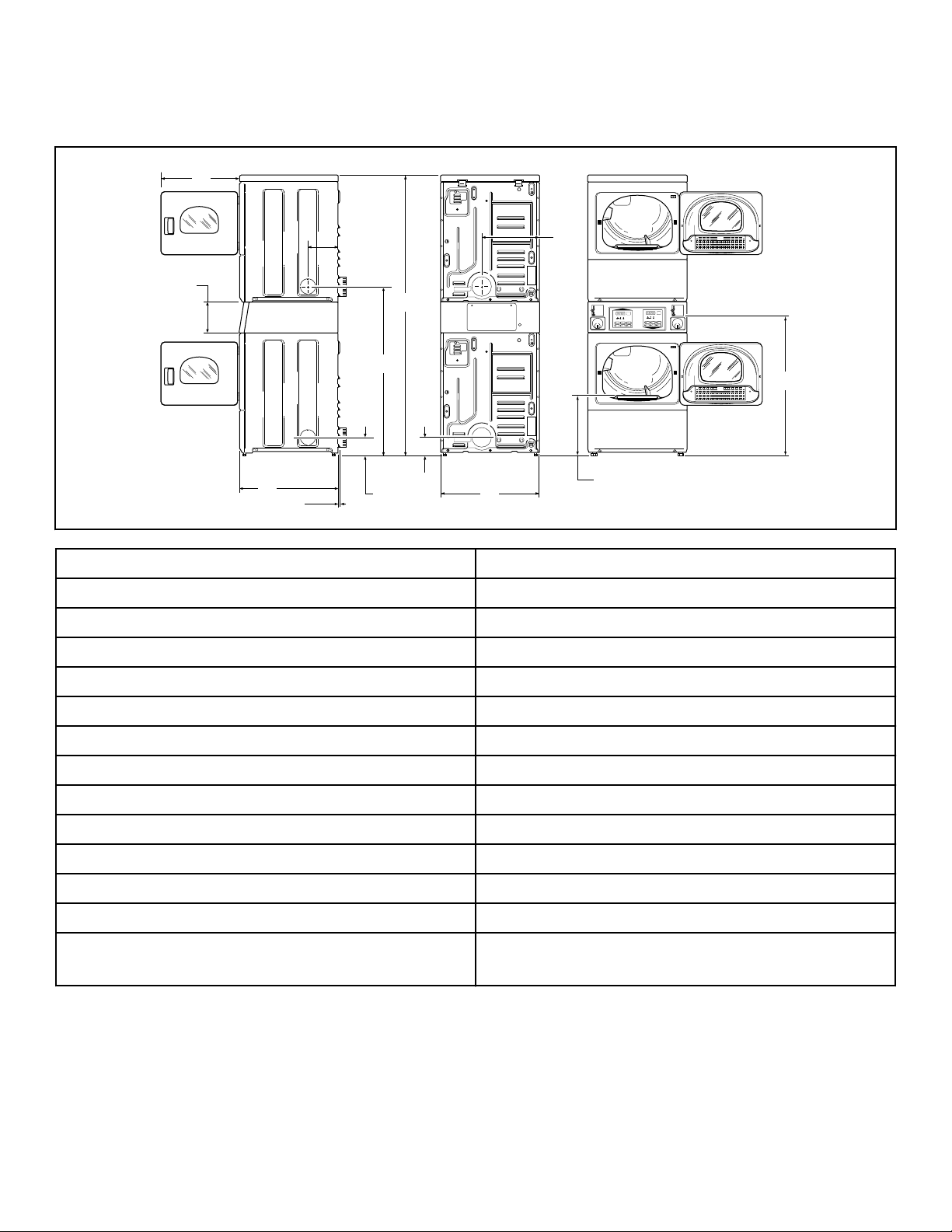
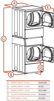
Dimensions
Electric Dryers
DRY2672N_SVG
M
L
K
J
I
H
G
F
E
D
C
B
A
A 23.5 in. [597 mm]
B 8.375 in. [213 mm]
C 28 in. [711 mm]
D 0.4 in. [11 mm]
E 8 in. [203 mm]
F 46.62 in. [1184 mm]
G *78.17 in. [1986 mm]
H *4 in. [102 mm]
I *4.5 in. [114 mm]
J 26.875 in. [683 mm]
K 15.4 in. [391 mm]
L *15.44 in. [392 mm]
M *39.13 in. [994 mm]
NOTE: Exhaust openings are 4 inch [102 mm] metal
ducting.
* With leveling legs turned into base.
Dimensions
©
Copyright, Alliance Laundry Systems LLC -
DO NOT COPY or TRANSMIT
9
Part No. D516906ENR1
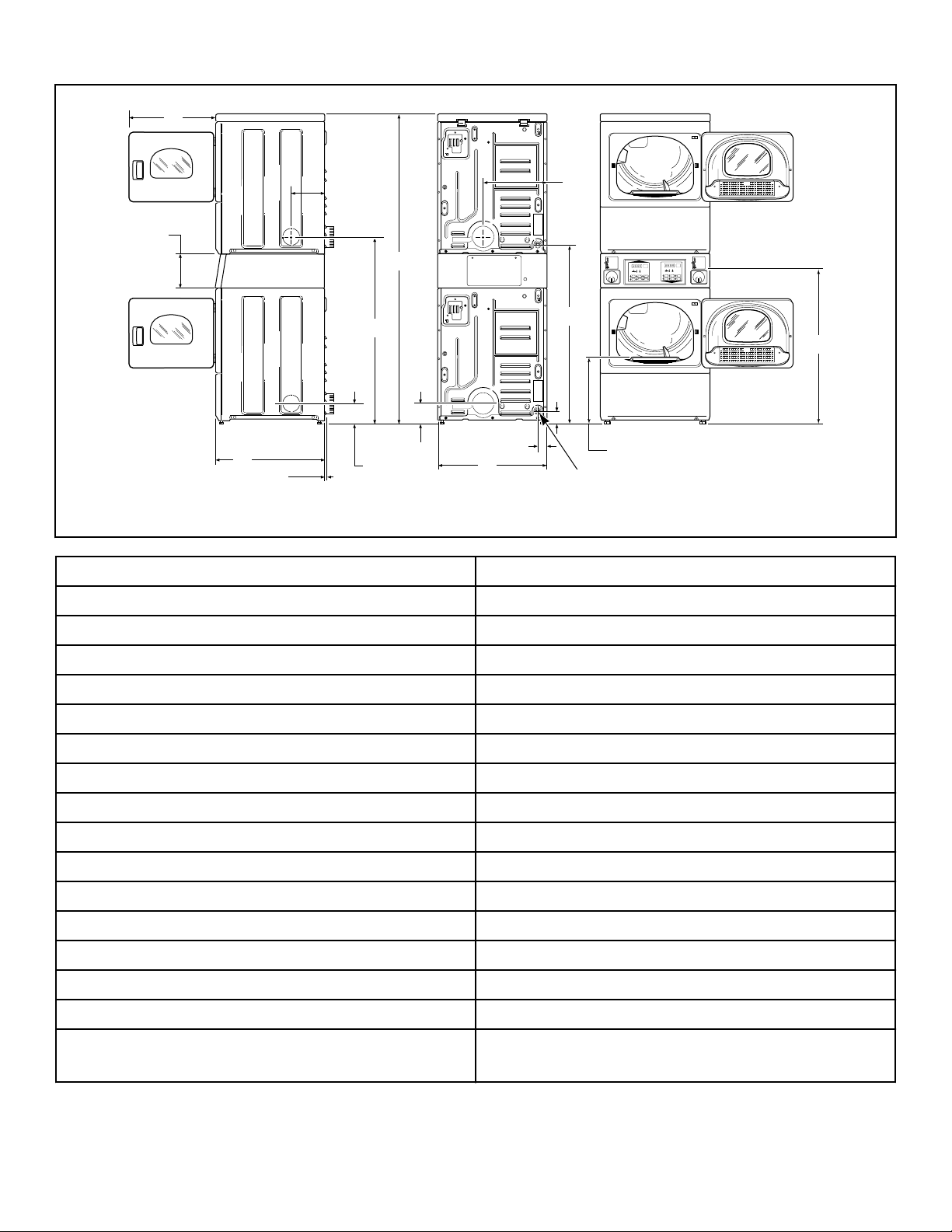
Gas Dryers
DRY2673N_SVG
P
O
N
M
L
K
J
I
H
G
F
E
D
C
B
A
1
1. 3/8 in. N.P.T. Gas Connection
A 23.5 in. [597 mm]
B 8.375 in. [213 mm]
C 28 in. [711 mm]
D 0.4 in. [11 mm]
E 8 in. [203 mm]
F 46.62 in. [1184 mm]
G *78.17 in. [1986 mm]
H *4 in. [102 mm]
I *4.5 in. [114 mm]
J 26.875 in. [683 mm]
K 2.3 in. [60 mm]
L 15.4 in. [391 mm]
M *44.87 in. [1140 mm]
N *2.8 in. [70 mm]
O *15.44 in. [392 mm]
P *39.13 in. [994 mm]
NOTE: Exhaust openings are 4 inch [102 mm] metal
ducting.
* With leveling legs turned into base.
NOTE: Gas models cannot be vented out left side of
cabinet because of burner housing.
Dimensions
©
Copyright, Alliance Laundry Systems LLC -
DO NOT COPY or TRANSMIT
10
Part No. D516906ENR1

IMPORTANT: The dryer should have sufficient clear-
ance around it for needed ventilation and for the ease
of installation and servicing. For maximum drying per-
formance, we recommend that more clearance be al-
lowed around the dryer than the clearances that are
listed throughout this manual.
Dimensions
©
Copyright, Alliance Laundry Systems LLC -
DO NOT COPY or TRANSMIT
11
Part No. D516906ENR1
Installation
Before You Start
Supplies
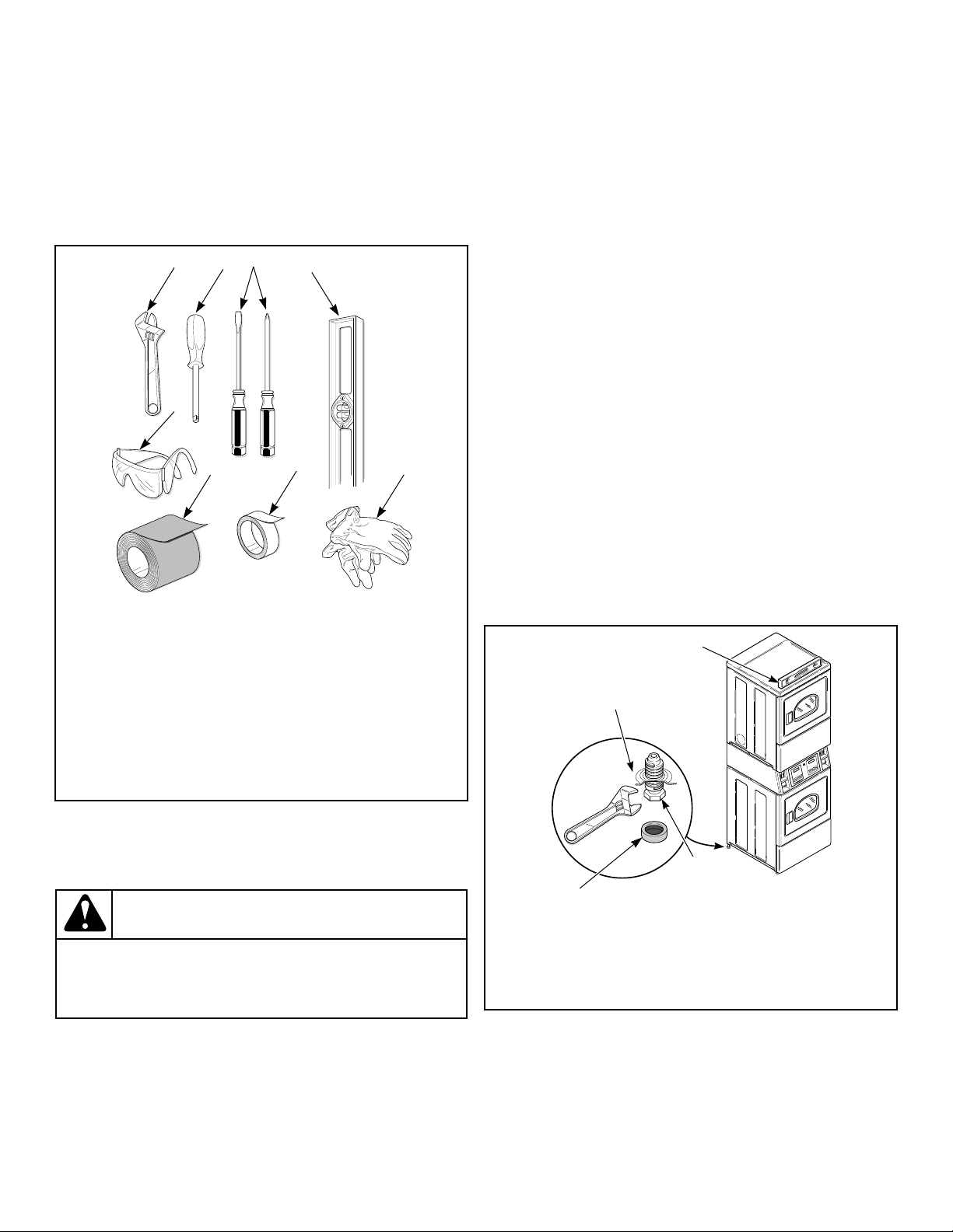
For most installations, the basic supplies you will need are:
DRY2586N_SVG
8
7
6
5
4
3
2
1
1. Wrench
2. 1/4 inch Driver
3. Screwdrivers
4. Level
5. Gloves
6. Teflon Tape
7. Duct Tape
8. Safety Glasses
Figure 1
NOTE: This appliance is suitable for use in countries
having a warm, damp climate.
WARNING
Any disassembly requiring the use of tools must be
performed by a suitably qualified service person.
W299
Additional Security
Torx security screws are available (as optional equipment at extra
cost) for securing lower access panel to each dryer base. Order
part number 62853.
A Torx bit, part number 282P4, is available (as optional equip-
ment at extra cost) for installing the Torx security screws.
A Torx bit holder, part number 24161, is available (as optional
equipment at extra cost) to be used with the Torx bit.
Position and Level the Dryer
1. Install the four rubber feet (in accessories bag).
2. Select a location with a solid floor. Dryers installed in resi-
dential garages must be elevated 18 inches [457 mm] above
the floor.
No other fuel burning appliance should be installed in the same
closet with the dryer.
The dryer must not be installed or stored in an area where it will
be exposed to water and/or weather.
The dryer needs suf
ficient clearance and an adequate air supply
for proper operation and ventilation, and for easier installation
and servicing. (Minimum clearances are shown in Figure 3 ).
3. Place the dryer in position, and adjust the legs until the dryer
is level from side to side and front to back. Leveling legs can
be adjusted from inside the dryer with a 1/4 in. driver.
4. All four legs must rest firmly on the floor so the weight of the
dryer is evenly distributed. The dryer must not rock.
DRY2539N_SVG
2
1
3
4
1. Dryer Base
2. Level
3. Leveling Leg
4. Rubber Foot
Figure 2
Installation
©
Copyright, Alliance Laundry Systems LLC -
DO NOT COPY or TRANSMIT
12
Part No. D516906ENR1
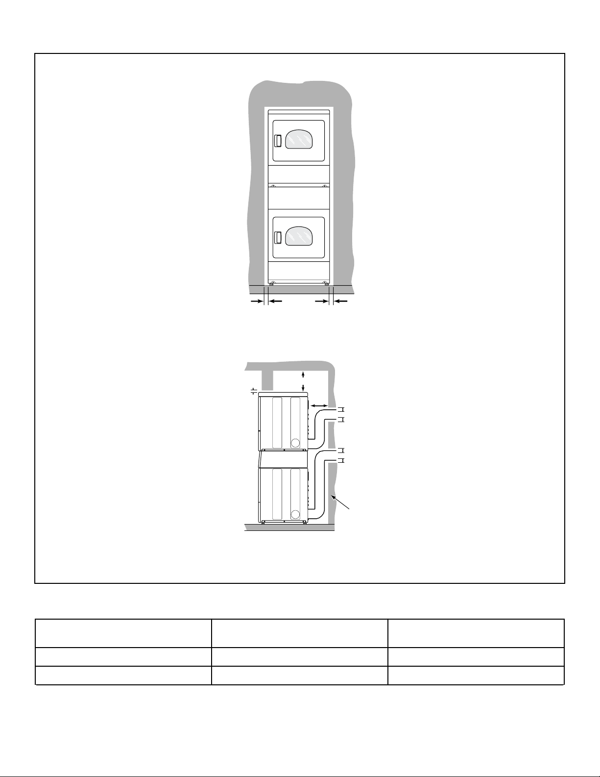
Front View
DRY2667N_SVG
A A
Side View
DRY2668N_SVG
B
E
E
D
C
1
1. Outer Wall of Enclosure
Figure 3
Area Description Free Standing/Alcove Installation
A Dryer sides 0 in. [0 mm]
B Dryer top (rear 24 in. [610 mm]) 12 in. [305 mm]
Table 1 continues...
Installation
©
Copyright, Alliance Laundry Systems LLC -
DO NOT COPY or TRANSMIT
13
Part No. D516906ENR1
Area Description Free Standing/Alcove Installation
C* Dryer rear 4 in. [102 mm]
D Dryer Top (front 4 in. [201 mm]) 0.5 in. [13 mm]
E Exhaust duct clearance to combustible ma-
terial
2 in. [51 mm]
* Rear clearance is minimum. 6 inches [152 mm] is recommended when venting through
rear of unit.
Table 1
NOTE: For new installations, it is suggested to locate
top of wall vent 42 inches (106.7 cm) above floor to
make venting easier to connect.
IMPORTANT: In mobile home installations, gas dryers
MUST be permanently attached to the floor at the time
of installation. Order No. 526P3 Hold Down Kit (availa-
ble at extra cost) for a manufactured (mobile) home in-
stallation. Follow the instructions supplied with the kit.
Installation of unit must conform to the Manufactured Home
Construction and Safety Standards, Title 24 CF4, Part 32-80 or
Standard CAN/CSA-Z240 MH.
IMPORTANT: Unless completely assembled, DO NOT
slide the dryer unit across the floor. DO NOT slide the
unit once the leveling legs have been extended, as the
legs and the base could become damaged.
Connect Dryer Exhaust System
WARNING
To reduce the risk of fire and combustion gas accu-
mulation the dryer MUST be exhausted to the out-
doors.
W604
WARNING
To reduce the risk of fire and the accumulation of
combustion gases, DO NOT exhaust dryer air into a
window well, gas vent, chimney or enclosed, unven-
tilated area, such as an attic, wall, ceiling, crawl
space under a building or concealed space of a
building.
W045
WARNING
This gas appliance contains or produces a chemical
or chemicals which can cause death or serious ill-
ness and which are known to the State of California
to cause cancer, birth defects, or other reproductive
harm. To reduce the risk from substances in the fuel
or from fuel combustion, make sure this appliance is
installed, operated, and maintained according to the
instructions in this manual.
W115
WARNING
To reduce the risk of fire, DO NOT use plastic or thin
foil ducting to exhaust the dryer
.
W354
WARNING
To reduce the risk of fire, the exhaust duct and
weather hood MUST be fabricated of a material that
will not support combustion. Rigid or flexible metal
pipe is recommended for a clothes dryer
.
W048
WARNING
To reduce the risk of fire due to increased static
pressure, we do not recommend installation of in-
line secondary lint filters or lint collectors. If secon-
dary systems are mandated, frequently clean the
system to assure safe operation.
W749
Installation
©
Copyright, Alliance Laundry Systems LLC -
DO NOT COPY or TRANSMIT
14
Part No. D516906ENR1
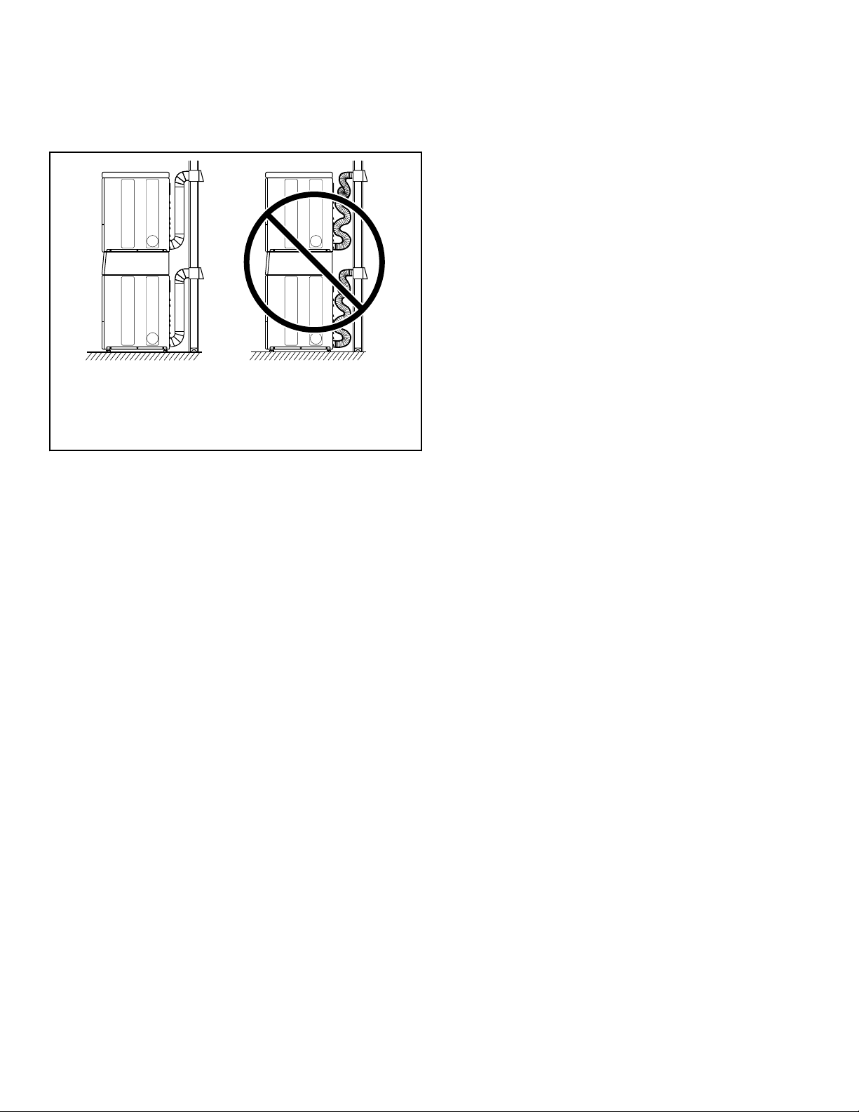
IMPORTANT: Installing in-line filters or lint collectors
will cause increased static pressure. Failure to main-
tain the secondary lint system will decrease dryer effi-
ciency and will void machine warranty.
DRY2540N_SVG
21
1. Correct
2. Incorrect
Figure 4
• DO NOT use plastic, thin foil or type B ducting. Rigid metal
duct is recommended.
• Locate dryer so exhaust duct is as short as possible.
• Be certain old exhaust ducts are cleaned before installing your
new dryer.
• Use 4 inch [102 mm] diameter rigid or flexible metal duct.
• The male end of each section of duct must point away from
the dryer.
• Use as few elbows as possible.
• Use of duct tape or pop-rivets on all seams and joints is rec-
ommended, if allowed by local codes. DO NOT use sheet
metal screws or fasteners on exhaust pipe joints which extend
into the duct and catch lint.
• Ductwork that runs through unheated areas must be insulated
to help reduce condensation and lint build-up on pipe walls.
• Install backdraft dampers in multi-dryer installations.
• In mobile home installations, dryer exhaust duct must be se-
cured to mobile home structure.
• Dryer exhaust duct MUST NOT terminate under mobile
home.
• Exhaust duct must not be connected to any other duct, vent, or
chimney.
• Dryer exhausts 220 cfm per unit (measured at back of dryer).
• DO NOT install flexible duct in concealed spaces, such as a
wall or ceiling.
• Static pressure in exhaust duct should not be greater than 0.6
inches water column [1.5 cm water column], measured with
manometer placed on exhaust duct 2 feet [610 mm] from dry-
er (check with dryer running and no load). In multi-dryer in-
stallations, all dryers connected to the main collector duct
should be operating when pressure is checked.
• Exhausting dryer in hard-to-reach locations can be done by
installing 521P3 Flexible Metal Vent Kit (available as option-
al equipment at extra cost).
• Sufficient make-up air must be supplied to replace the air ex-
hausted by the dryer. The free area of any opening for outside
air must be at least 40 in.
2
[25806 mm
2
] per unit.
•
Energy efficient buildings with low air infiltration rates
should be equipped with an air exchanger that can accommo-
date on demand make-up air needs in the laundry room. These
devices can be obtained through your building contractor or
building material suppliers.
• Do not draw make-up air from a room containing a gas fired
water heater, a dry cleaner or a hair salon.
• Failure to exhaust dryer properly will void warranty.
• A dryer will dissipate 60 Btu/ft
2
[681,392 J/m
2
] of surface
area exposed to the conditioned air.
NOTE: Venting materials are not supplied with the dry-
er (obtain locally).
IMPORTANT: DO NOT block the airflow at the bottom of
the dryer’s front panel with laundry, rugs, etc. Blockage
will decrease airflow through the dryer, thus reducing
the efficiency of the dryer.
Exhaust Direction
The dryer can be exhausted to the outdoors through the back, left,
right or bottom of the dryer. EXCEPTION: Gas dryers cannot be
vented out the left side because of the burner housing.
Dryer is shipped from factory ready for rear exhaust.
Exhausting the dryer through sides or bottom can be accomplish-
ed by installing a Directional Exhaust Kit, 528P3, available as
optional equipment at extra cost.
Exhaust System
For best drying results, recommended maximum length of ex-
haust system is shown in Table 2 .
To prevent backdraft when dryer is not in operation, outer end of
exhaust pipe must have a weather hood with hinged dampers (ob-
tain locally).
NOTE: Weather hood should be installed at least 12 in-
ches [305 mm] above the ground. Larger clearances
may be necessary for installations where heavy snow-
fall can occur.
Installation
©
Copyright, Alliance Laundry Systems LLC -
DO NOT COPY or TRANSMIT
15
Part No. D516906ENR1
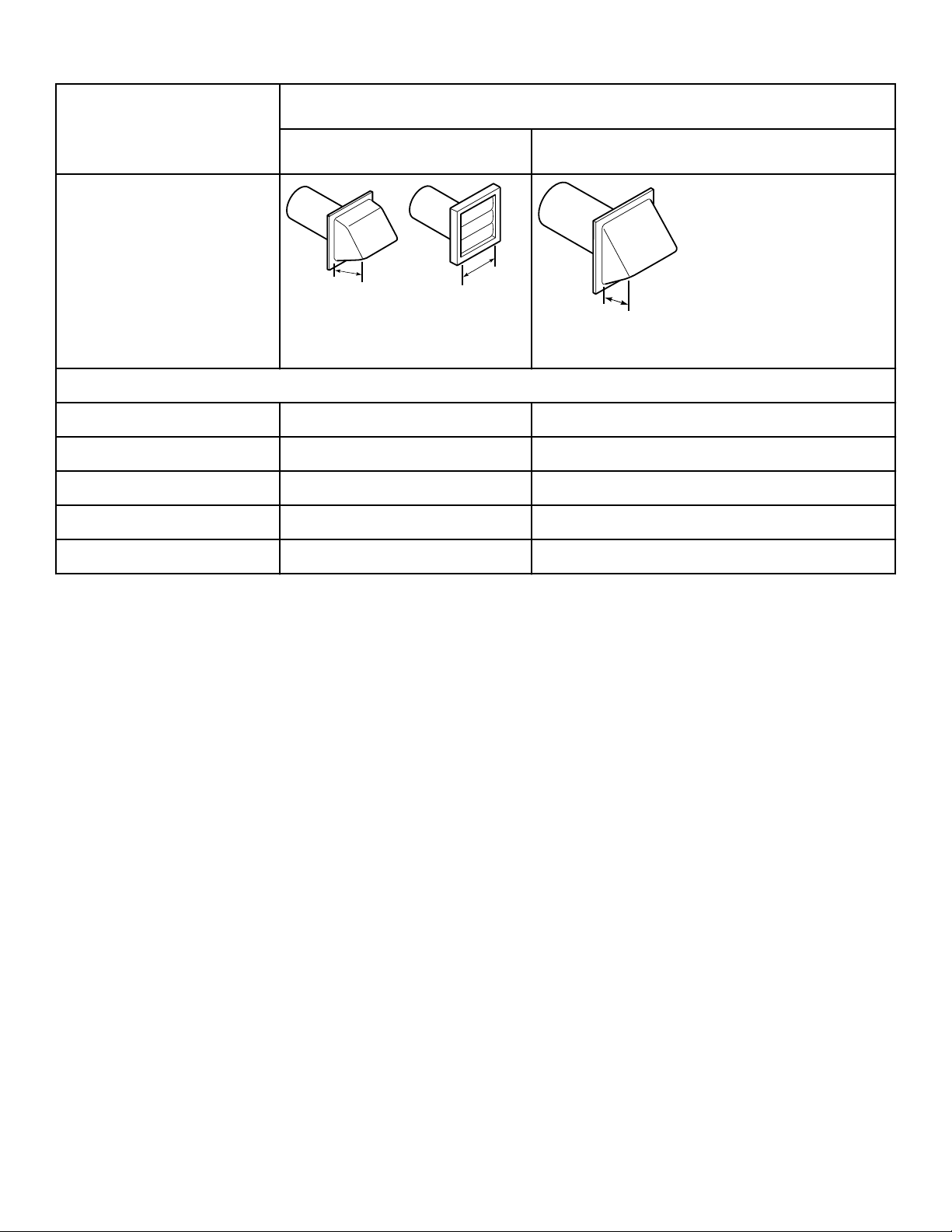
Number of 90° Elbows
Weather Hood Type
Recommended Use Only for Short Run Installations
D673I_SVG
1
1
1. 4 in. [102 mm]
D802I_SVG
1
1. 2.5 in. [64 mm]
Maximum length of 4 in. [102 mm] diameter rigid metal duct.
0 65 feet [19.8 m] 55 feet [16.8 m]
1 55 feet [16.8 m] 47 feet [14.3 m]
2 47 feet [14.3 m] 41 feet [12.5 m]
3 36 feet [11.0 m] 30 feet [9.1 m]
4 28 feet [8.5 m] 22 feet [6.7 m]
Table 2
NOTE: Deduct 6 feet [1.8 m] for each additional elbow.
NOTE: The maximum length of a 4 in. [102 mm] diame-
ter flexible metal duct must not exceed 7.87 ft. [2.4 m],
as required to meet UL2158, clause 7.3.2.A.
Multi-Dryer Installation Exhaust Requirements
Figure 5 shows a typical example of a multiple dryer installation.
Note how each dryer has its own exhaust system vented to the
central exhaust duct.
Installation
©
Copyright, Alliance Laundry Systems LLC -
DO NOT COPY or TRANSMIT
16
Part No. D516906ENR1
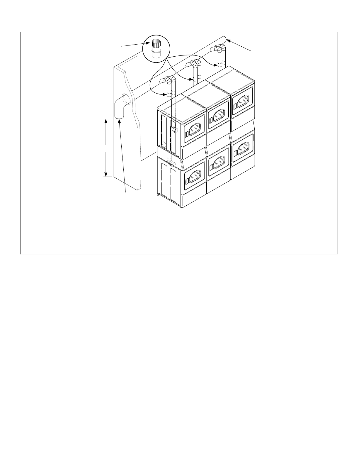
DRY2674N_SVG
3
2
1
4
1. 58786 Backdraft Damper (Available through your local authorized parts source)
2. Clean Out Cover (Must be provided). Inspect monthly.
3. Weather Hood or Sweep Elbow (No cap or screen)
4. 24 in. [610 mm] Minimum Clearance to Roof/Ground
Figure 5
Installation
©
Copyright, Alliance Laundry Systems LLC -
DO NOT COPY or TRANSMIT
17
Part No. D516906ENR1
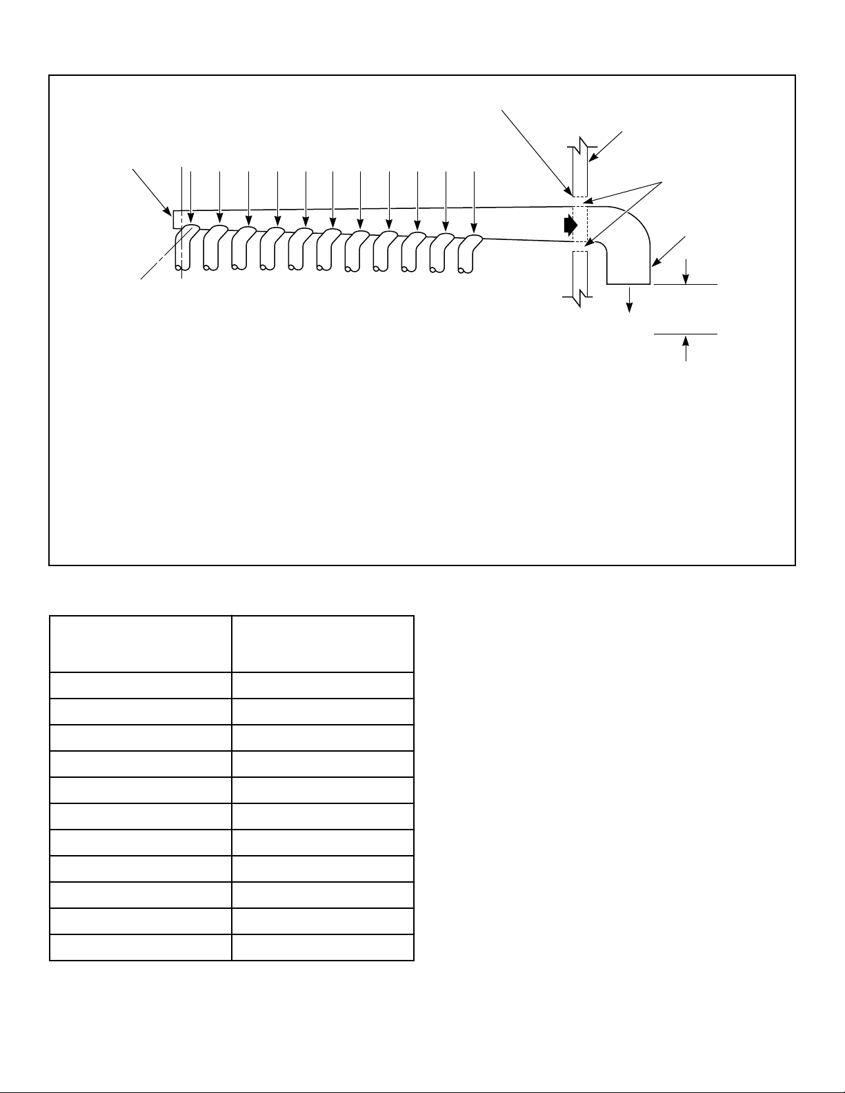
Horizontal Exhaust Installation: Exhaust Air Flow Maximum Length of Duct 30 feet [9.1 m]
D686I_SVG
8
6
5
7
A
B C D E F G H I J K
9
3
2
4
1
1. Where the exhaust duct pierces a combustible wall or ceiling, the opening must be sized per local codes.
2. Wall
3. 2 in. [50 mm] Minimum or Clearance per Local Codes
4. No Screen or Cap
5. 24 in. [610 mm] Minimum Clearance to Roof/Ground
6. Exhaust Outlet
7. Air Flow
8. 30 °
9. Clean Out Cover - Inspect Monthly
Figure 6
Duct Station
Minimum Diameter of
Collector Duct
A 4 inches [102 mm]
B 8 inches [203 mm]
C 9 inches [229 mm]
D 10 inches [254 mm]
E 11 inches [279 mm]
F 12 inches [305 mm]
G 13 inches [326 mm]
H 14 inches [356 mm]
I 15 inches [381 mm]
J 15 inches [381 mm]
K 16 inches [406 mm]
Table 3
Installation
©
Copyright, Alliance Laundry Systems LLC -
DO NOT COPY or TRANSMIT
18
Part No. D516906ENR1
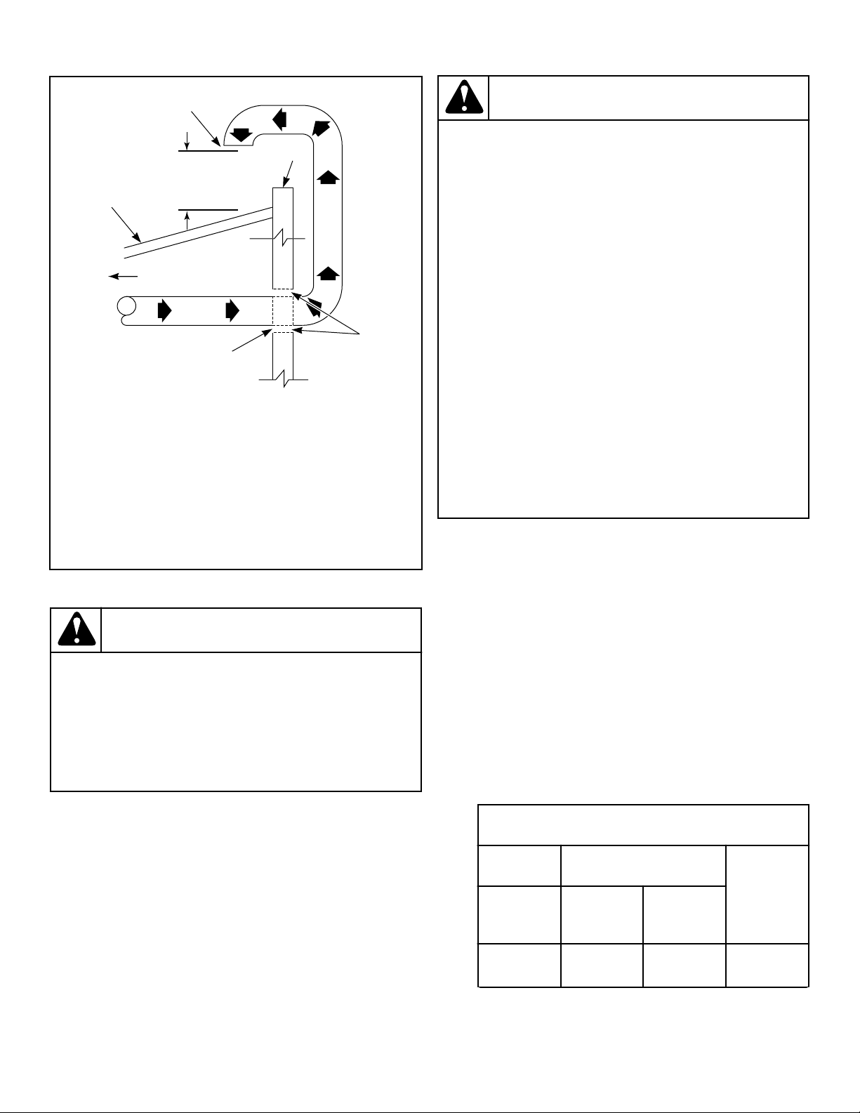
Vertical Exhaust Installation
D753I_SVG
7
2
6
5
4
3
1
1. Roof
2. 24 in. [610 mm] Minimum Clearance to Roof/Ground
3. No Screen or Cap
4. Wall
5. 2 in. [50 mm] Minimum
6. Where the exhaust duct pierces a combustible wall or ceil-
ing, an opening must be sized as shown or per local codes.
7. Connect to Dryer
Figure 7
WARNING
To reduce the risk of fire and the accumulation of
combustion gases, DO NOT exhaust dryer air into a
window well, gas vent, chimney or enclosed, unven-
tilated area, such as an attic, wall, ceiling, crawl
space under a building or concealed space of a
building.
W045
A Backdraft Damper, Part No. 58786 (obtain locally),should be
installed in a 4 inch [102 mm] diameter VERTICAL duct system.
This will prevent a backdraft when dryer is not in use, and will
keep the exhaust air in balance within the central exhaust system.
Gas Dryers - Connect Gas Supply Pipe
WARNING
To reduce the risk of gas leaks, fire or explosion:
• Each dryer must be connected to the type of gas
as shown on nameplate located in the door re-
cess.
• Use a new flexible stainless steel connector.
• Use pipe joint compound insoluble in L.P. (Lique-
fied Petroleum) Gas, or Teflon tape, on all pipe
threads.
• Purge air and sediment from gas supply line be-
fore connecting it to the dryer. Before tightening
the connection, purge remaining air from gas line
to each dryer until odor of gas is detected. This
step is required to prevent gas valve contamina-
tion.
• Do not use an open flame to check for gas leaks.
Use a non-corrosive leak detection fluid.
• Any disassembly requiring the use of tools must
be performed by a suitably qualified service per-
son.
W315
1. Make certain your dryer is equipped for use with the type of
gas in your laundry room. Dryer is equipped at the factory for
Natural Gas with a 3/8 inch NPT gas connection.
NOTE: The gas service to a gas dryer must conform
with the local codes and ordinances, or in the ab-
sence of local codes and ordinances, with the latest
edition of the National Fuel Gas Code ANSI Z223.1/
NFPA 54 or the CAN/CSA-B149.1 Natural Gas and
Propane Installation Code.
Natural Gas, 1000 Btu/ft
3
[37.3 MJ/m
3
], service must be supplied
at minimum 5.0 inch water column pressure to maximum 10.5
inch water column pressure.
For proper operation at altitudes above 2000 feet [610 m] the nat-
ural gas valve spud orifice size must be reduced to ensure com-
plete combustion. Refer to Table 4 .
Natural Gas Altitude Adjustments
Altitude Orifice Size
Part
Numberfeet [m] #
inches
[mm]
2,000 [610] 41 0.0960
[2.44]
D503776
Table 4 continues...
Installation
©
Copyright, Alliance Laundry Systems LLC -
DO NOT COPY or TRANSMIT
19
Part No. D516906ENR1
Natural Gas Altitude Adjustments
Altitude Orifice Size
Part
Numberfeet [m] #
inches
[mm]
3,000 [915] 42 0.0935
[2.37]
D503777
5,500
[1,680]
43 0.0890
[2.26]
D503778
7,000
[2,135]
44 0.0860
[2.18]
58719
9,000
[2,745]
45 0.0820
[2.08]
D503779
10,500
[3,200]
46 0.0810
[2.06]
D503780
Table 4
2. Remove the shipping cap from the gas connection at the rear
of the dryer. Make sure you do not damage the pipe threads
when removing the cap.
NOTE: If gas supply connection is British Standard
Pipe Tapered thread (BSPT), order 44178804 brass
female NPT (FPT) to male BSPT gas pipe thread
adapter, available at extra cost.
3. Connect to gas supply pipe using thread sealant or Teflon
tape. Torque 90 - 175 inch-pounds [10.2 - 19.7 Nm].
NOTE: The connection of gas supply to the appli-
ance shall be made with a flexible hose suitable for
the appliance category in accordance with national
installation regulations of the country of destina-
tion. If in doubt contact the dryer distributor or man-
ufacturer.
NOTE: When connecting to a gas line, an equipment
shut-off valve in accordance with the National Fuel
Gas Code, ANSI Z223.1/NFP
A 54 and the Natural
Gas and Propane Installation Code, CSA B149.1
must be installed within 6 feet [1.8 m] of the dryer.
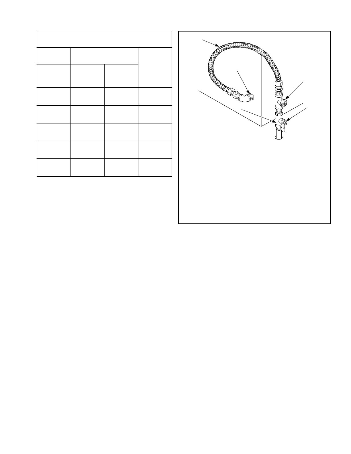
An 1/8 in. NPT pipe plug must be installed as shown
for checking inlet pressure. Refer to Figure 8 .
D233I_SVG
2
3
4
1
5
1. New Stainless Steel Flexible Connector – (Use design
CSA certified connector) Use only if allowed by local co-
des
2. 1/8 in. NPT Pipe Plug
3. Equipment Shut-Off Valve
4. Black Iron Pipe:
Shorter than 20 ft. [6.1 m] – Use 3/8 in. [9.5 mm] pipe.
Longer than 20 ft. [6.1 m] – Use 1/2 in. [12.7 mm] pipe.
5. 3/8 in. NPT Gas Connection
Figure 8
4. Tighten all connections securely but don't overtighten to avoid
breaking or bending the gas valve bracket. Turn on gas and
check all pipe connections (internal & external) for gas leaks
with a non-corrosive leak detection fluid.
NOTE: The dryer and its appliance main gas valve must
be disconnected from the gas supply piping system
during any pressure testing of that system at test pres-
sures in excess of 1/2 psi [3.45 kPa]. Refer to Check
Heat Source.
NOTE: DO NOT connect the dryer to L.P. Gas Service
without converting the gas valve. Install L.P. Gas Con-
version Kit 458P3, available at extra cost.
L.P. (Liquefied Petroleum) Gas, 2500 Btu/ft.
3
[93.1 MJ/m
3
], serv-
ice must be supplied at 10 ± 1.5 inch water column pressure.
For proper operation at altitudes above 3500 feet [1070 m] the
L.P. gas valve spud orifice size must be reduced to ensure com-
plete combustion. Refer to Table 5 .
Installation
©
Copyright, Alliance Laundry Systems LLC -
DO NOT COPY or TRANSMIT
20
Part No. D516906ENR1
L.P. Altitude Adjustments
Altitude Orifice Size
Part No.feet [m] No.
inches
[mm]
3500 [1070] 54 0.0550 [1.40] D503785
7500 [2290] 55 0.0520 [1.32] 58755
11000 [3355] 56 0.0465 [1.18] D503786
Table 5
Electric Dryer Only - Connect Electrical
Plug
Dryer requires 120/240 Volt or 120/208 Volt, 60 Hertz, 3 or 4
wire electrical supply. Refer to serial plate for specific electrical
requirements.
IMPORTANT: Use only a new U.L. listed No. 10 (copper
wire only) three or four conductor power supply cord
kit rated 240 Volts (minimum) 30 Amperes and labeled
as suitable for use in a clothes dryer.
NOTE: The wiring diagram is located behind the con-
trol panel, inside the control cabine
WARNING
To reduce the risk of fire, electric shock, serious in-
jury or death, all wiring and grounding MUST con-
form with the latest edition of the National Electrical
Code, ANSI/NFPA 70, or the Canadian Electrical
Code, CSA C22.1, and such local regulations as
might apply. It is the customer’s responsibility to
have the wiring and fuses installed by a qualified
electrician to make sure adequate electrical power is
available to the dryer.
W521
Earth/Ground Information
This appliance must be properly connected to protective earth/
ground. In the event of malfunction or breakdown, the earth/
ground will reduce the risk of electric shock by providing a path
of least resistance for electric current.
The cord-kit must be equipped with a cord having an equipment-
earth/ground conductor and an earth/ground plug. The plug must
be plugged into an appropriate outlet that is properly installed and
connected to a protective earth/ground in accordance with all lo-
cal codes and ordinances.
WARNING
Improper connection of the equipment earth/ground
conductor can result in a risk of electric shock.
Check with a qualified electrician or service person if
you are in doubt as to whether the dryer is properly
connected to a protective earth/ground.
W886
Do not modify the plug provided with the cord-kit - if it will not
fit the outlet, have a proper outlet installed by a qualified electri-
cian.
The dryer has its own terminal block that must be connected to a
separate branch, 60 Hertz, single phase circuit, AC (alternating
current) circuit, fused at 30 Amperes (the circuit must be fused on
both sides of the line). Electrical service for the dryer should be
of maximum rated voltage (208 or 240 Volt, depending on heat-
ing element) listed on the serial plate. Do not connect dryer to
110, 115, or 120 Volt circuit.
Heating elements are available for field installation in dryers
which are to be connected to electrical service of different volt-
age than that listed on serial plate, such as 208 Volt.
NOTE: Branch circuit wire size requirements to laundry
room outlet are shown in table below.
Wire Length Wire
Less than 15 ft. [4.5 m] Listed No. 10 AWG Copper
wire only
Longer than 15 ft. [4.5 m] Listed No. 8 AWG Copper
wire only
Table 6
The power cord connection between wall receptacle and dryer
terminal block IS NOT supplied with dryer. Type of power cord
and gauge of wire must conform to local codes.
IMPORTANT: Use only a new U.L. listed No. 10 (copper
wire only) three or four conductor power supply cord
kit rated 240 Volts (minimum) 30 Amperes and labeled
as suitable for use in a clothes dryer.
Installation
©
Copyright, Alliance Laundry Systems LLC -
DO NOT COPY or TRANSMIT
21
Part No. D516906ENR1
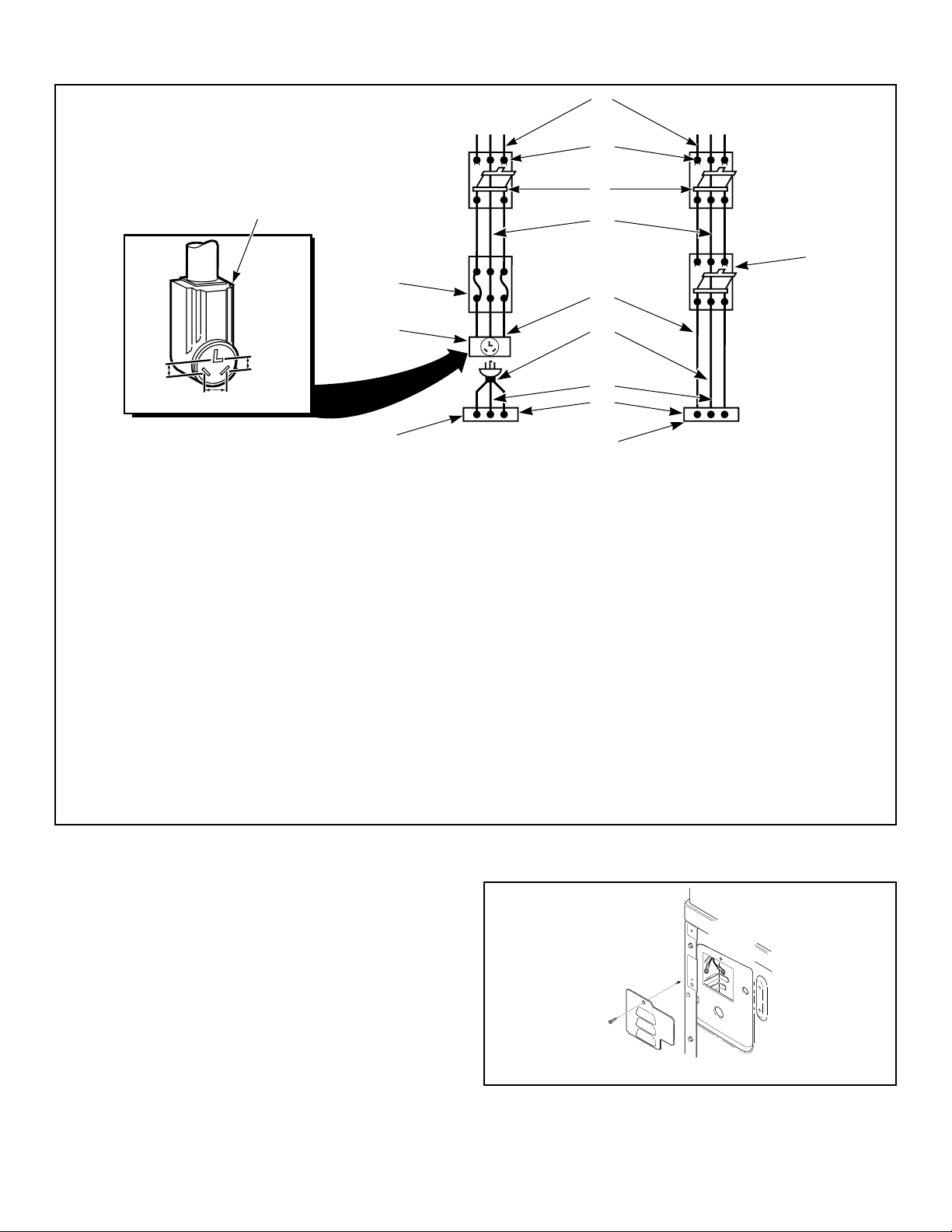
Three-Wire
D275I_SVG
3
2
1
4
Four-Wire
D006I_SVG
3
2
1
4
1. Typical Receptacle
2. Power Cord
3. Stain Relief Nut
4. Strain Relief
Figure 9
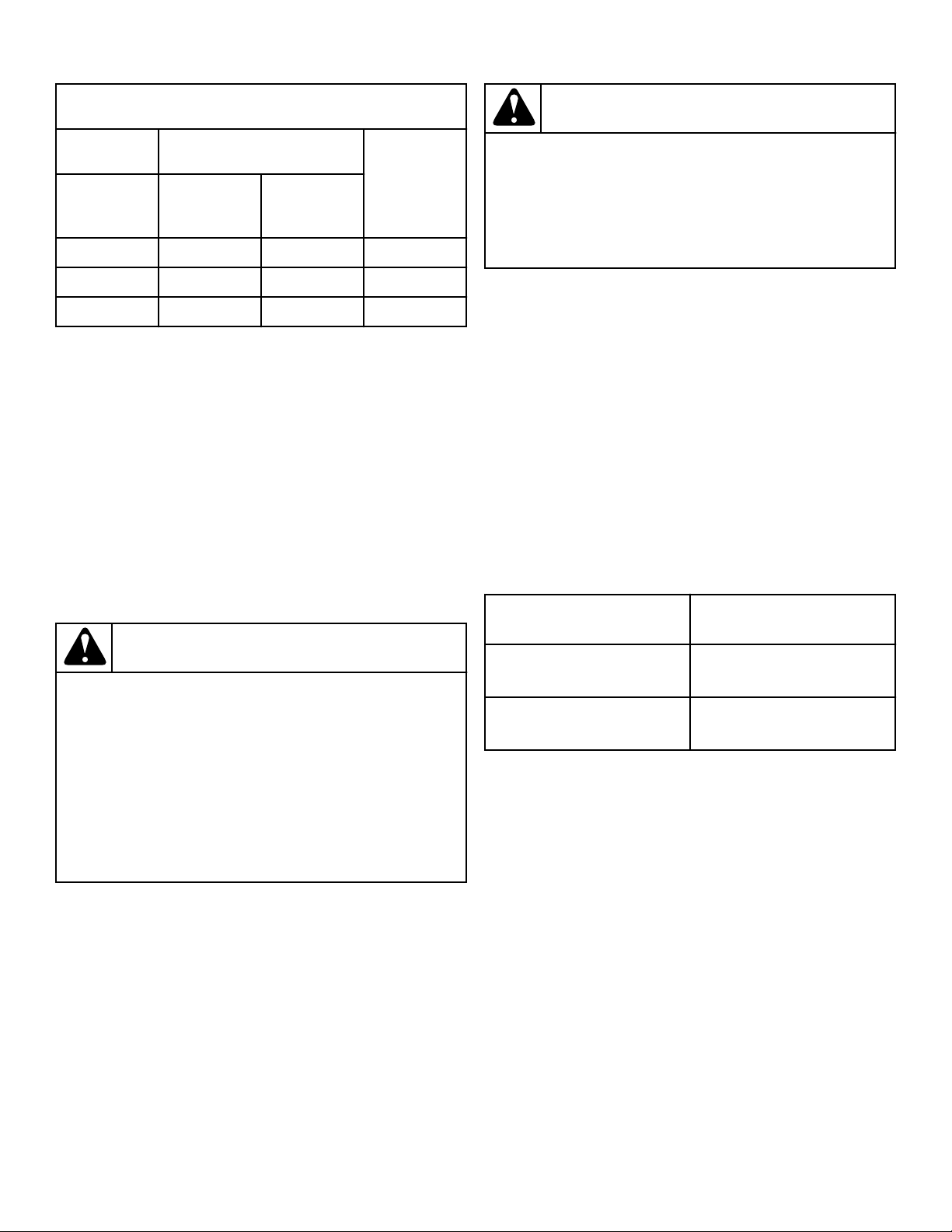
Three-Wire Connection
D679I_SVG
8
7
6
5
4
3
2
1
1. Ground Wire
2. Ground to Neutral Wire
3. Neutral Terminal
4. “L2” Terminal
5. Center Wire (Neutral)
6. Strain Relief (Not supplied with dryer)
7. Ground Screw
8. “L1” Terminal
Figure 10
Installation
©
Copyright, Alliance Laundry Systems LLC -
DO NOT COPY or TRANSMIT
22
Part No. D516906ENR1
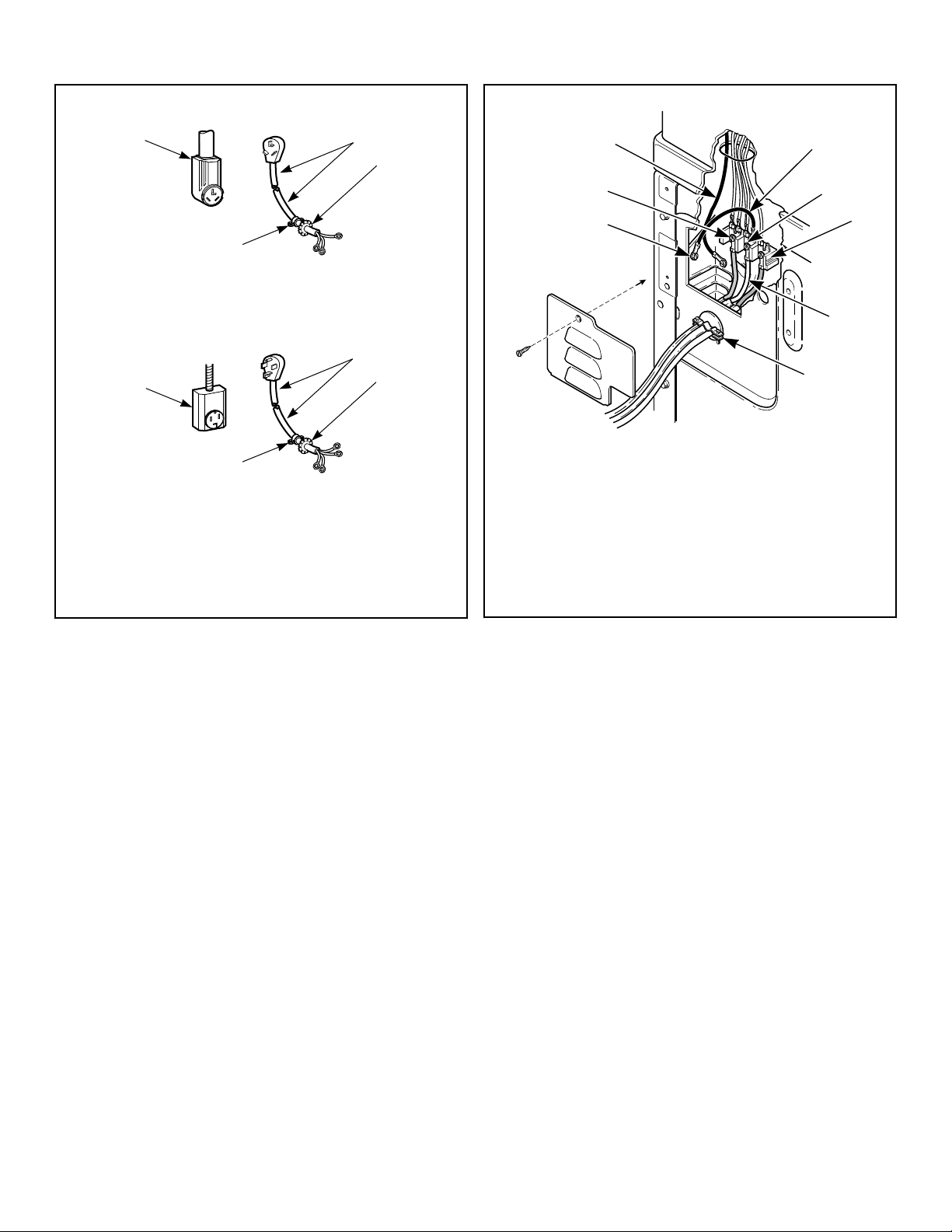
Four-Wire Connection
D680I_SVG
1
2
1
9
8
7
6
5
4
3
1. Ground Wire
2. Ground Screw
3. “L1” Terminal
4. Neutral Terminal
5. “L2” Terminal
6. Black Wire
7. White Wire (Neutral)
8. Strain Relief (Not supplied with dryer)
9. Red Wire
Figure 11
NOTE: Dryer is shown with access cover removed for
illustration purposes only. NEVER operate the dryer
with access cover removed.
Connecting Power Cord with Three-Wire Plug
NOTE: Four-wire cord is required for new branch-cir-
cuit installations, mobile homes or where codes do not
permit grounding through neutral.
NOTE: The power cord is NOT supplied with the elec-
tric dryer. Type of power cord and gauge of wire must
conform to local codes and instructions. The method
of wiring the dryer is optional and subject to local code
requirements.
NOTE: Connect the dryer to the power supply with the
MAXIMUM RATED VOLTAGE listed on the serial plate.
NOTE: Use COPPER WIRE only.
Shorter than 15 ft. (4.5 m) – use 10 AWG
Longer than 15 ft. (4.5 m) – use 8 A
WG
Installation
©
Copyright, Alliance Laundry Systems LLC -
DO NOT COPY or TRANSMIT
23
Part No. D516906ENR1
D816I_SVG
L1 L2 L1 L2
15
16
5
2
2
3
4
8
9
12
13
10
11
7
6
1
14
1. A typical 30-Amp Three-Wire Receptacle NEMA Type 10-30R
2. 120 ± 12 V.A.C.
3. 240 ± 12 V.A.C.
4. Intermediate Fuse Box (may be omitted if service entrance box is fused)
5. Wall Receptacle
6. Power Supply
7. 3-Wire Earth/Ground Neutral 120/240 Volt, 60 Hertz AC 1 Phase Service Entrance Switch Box (Refer to NOTE above)
8. 30 Ampere Fuses or Circuit Breaker
9. Neutral Wire
10. Metallic or Non-Metallic Sheathed Cable (Copper Wire Only)
11. Power Cord (Not supplied with dryer)
12. Neutral
13. Terminal Block in Dryer
14. Intermediate Shut-Off Box (may or may not be fused)
15. Direct Connection
16. Power Cord Connection
Figure 12
1. Disconnect power to dryer.
2. Remove access cover from rear of dryer.
D695I_SVG
Figure 13
Installation
©
Copyright, Alliance Laundry Systems LLC -
DO NOT COPY or TRANSMIT
24
Part No. D516906ENR1
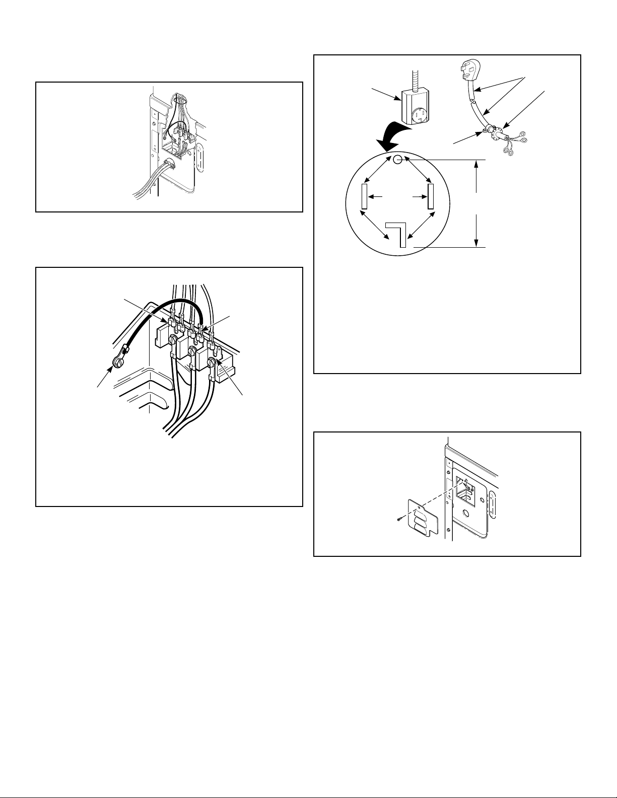
3. Use a strain relief and insert end of power cord through power
supply hole.
D696I_SVG
Figure 14
4. Use the three screws from the accessories bag to attach the
power cord wires to the terminal block. Refer to Figure 15 .
3-Wire Connection
DRY2508N_SVG
4
3
2
1
1. "L1" Terminal
2. Neutral Terminal
3. "L2" Terminal
4. Earth/Ground to Bulkhead
Figure 15
5. Using a screwdriver, tighten all screws firmly.
IMPORTANT: Failure to tighten these screws firmly
may result in wire failure at the terminal block.
6. Secure the strain relief to the power cord, or wires, where they
enter the dryer cabinet.
7. Check the continuity of the earth/ground connection before
plugging the cord into an outlet. Use an acceptable indicating
device connected to the center earth/ground pin of the plug
and the green screw on the back of the cabinet.
8. Reinstall access cover and screw.
Connecting Power Cord with Four-Wire Plug
NOTE: Four-wire cord is required for new branch-cir-
cuit installations, mobile homes or where codes do not
permit grounding through neutral.
DRY2016N_SVG
7
7
7
7
6
3
2
1
4
5
1. Typical Four-Wire Receptacle
2. Power Cord – Not Supplied with Dryer
3. Strain Relief Nut
4. Strain Relief
5. 0 V.A.C.
6. 240 ± 12 V.A.C.
7. 120 ± 12 V.A.C.
Figure 16
1. Disconnect power to dryer.
2. Remove access cover from rear of dryer.
DRY2467N_SVG
Figure 17
3. Remove earth/ground screw from earth/ground to neutral wire
and save for use in Step 5. Earth/ground to neutral wire will
be attached to the neutral terminal in Step 6.
Installation
©
Copyright, Alliance Laundry Systems LLC -
DO NOT COPY or TRANSMIT
25
Part No. D516906ENR1
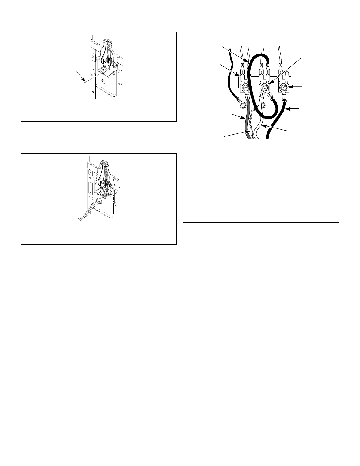
DRY2468N_SVG
1
1. Earth/Ground Screw
Figure 18
4. Use a strain relief and insert end of power cord through power
supply hole.
DRY2469N_SVG
1. Strain Relief
Figure 19
5. Attach power cord earth/ground (green) wire to rear bulkhead
using earth/ground screw removed in Step 3.
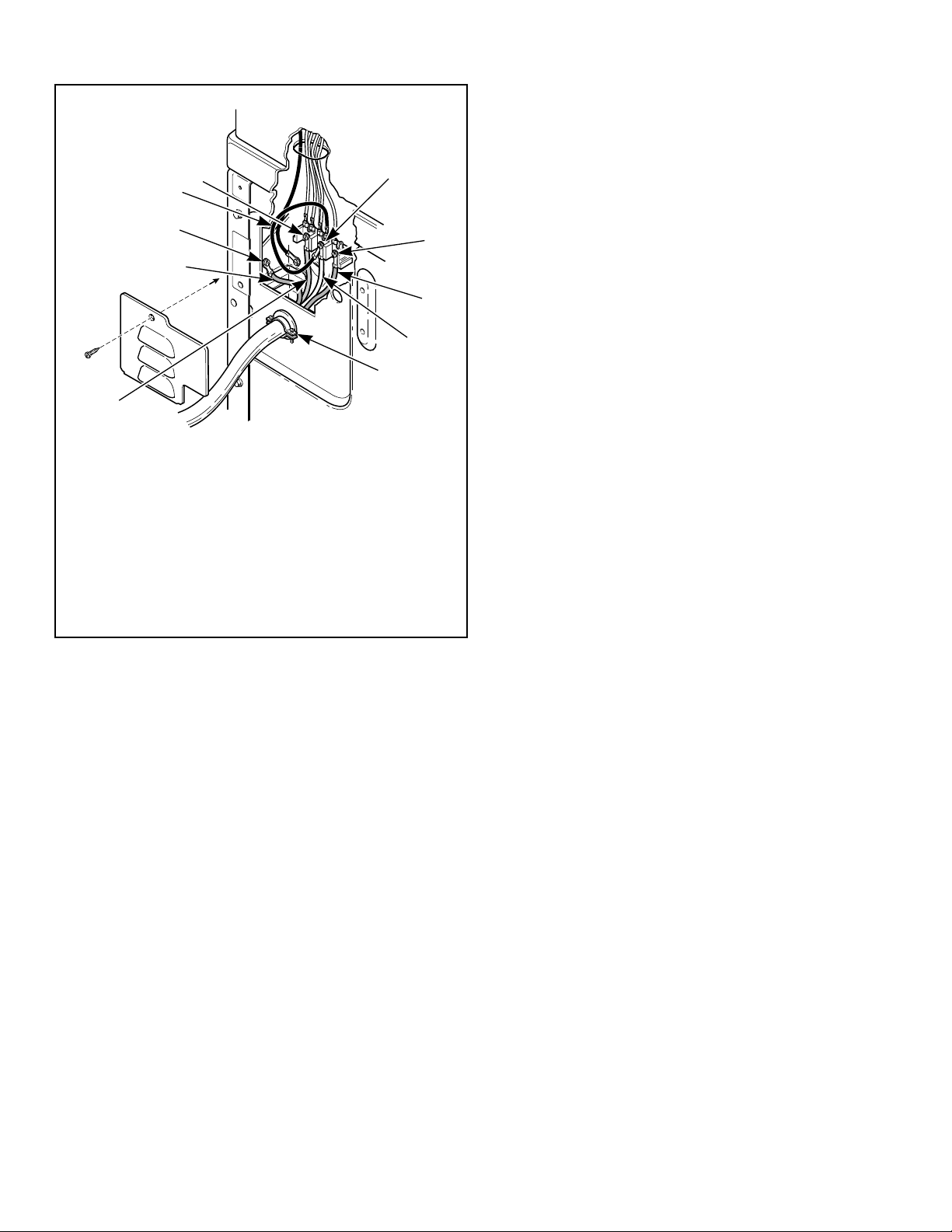
4-Wire Connection
DRY2482N_SVG
1
2
3
4
5
6
7
8
1. Neutral Terminal
2. “L2” Terminal
3. Black
4. White
5. Earth/Ground
6. Red
7. “L1” Terminal
8. Earth/Ground to Neutral Wire
Figure 20
6. Use the three screws from the accessories bag to attach the re-
maining power cord wires to the terminal block as follows:
a. Red wire to “L1” terminal.
b. Black wire to “L2” terminal.
c. White wire to Neutral terminal.
NOTE: When installing the white wire, loop the free
eyelet end of the earth/ground to neutral wire (re-
moved in Step 3) and attach along with the white
wire to the neutral (center) terminal on the terminal
block.
7. Using a screwdriver, tighten all screws firmly.
IMPORTANT: Failure to tighten these screws firmly
may result in wire failure at the terminal block.
8. Secure the strain relief to the power cord, or wires, where they
enter the dryer cabinet.
9. Check the continuity of the earth/ground connection before
plugging the cord into an outlet. Use an acceptable indicating
device connected to the center earth/ground pin of the plug
and the green screw on the back of the cabinet.
10. Reinstall access cover and screw.
Reverse Door, if Desired
NOTE: Doors with windows cannot be reversed.
Installation
©
Copyright, Alliance Laundry Systems LLC -
DO NOT COPY or TRANSMIT
26
Part No. D516906ENR1
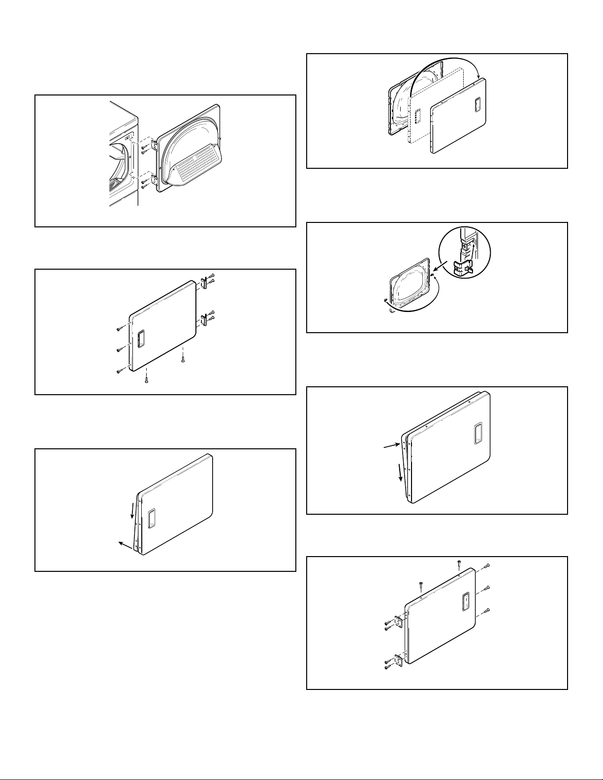
The door on this dryer is completely reversible. To reverse door
proceed as follows:
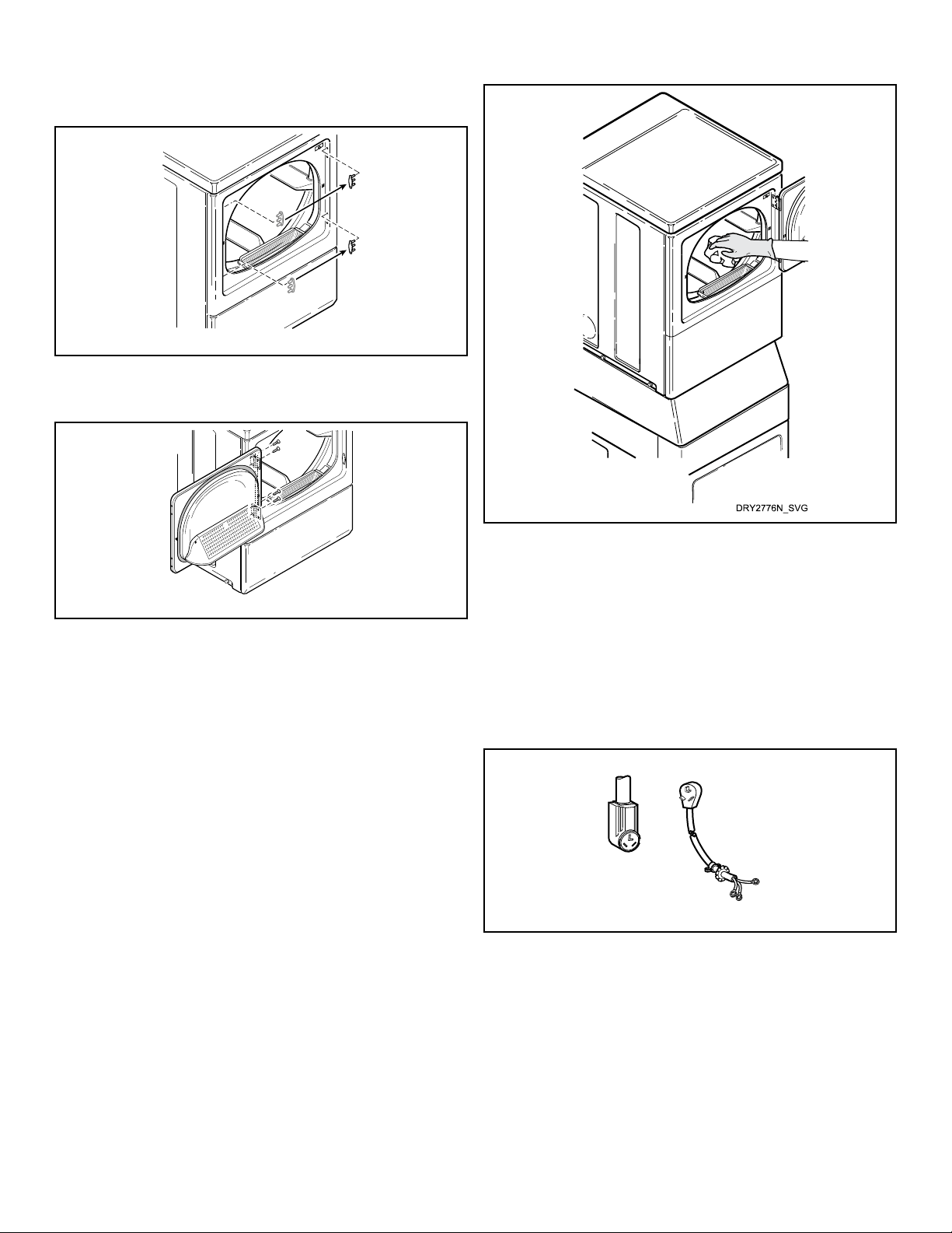
1. Remove four hinge attaching screws.
D675I_SVG
Figure 21
2. Remove all nine screws.
D272P_SVG
Figure 22
3. Pull bottom of door liner out, then pull down, removing door
liner from door panel.
DRY1916N_SVG
B
A
Figure 23
4. Rotate door panel 180 degrees as shown.
D273P_SVG
Figure 24
5. Remove door strike from door liner and reinstall on opposite
side.
DRY1917N_SVG
Figure 25
6. Insert liner under flange on bottom of door, then push top of
door liner into place.
DRY1918N_SVG
B
A
Figure 26
7. Reinstall nine screws removed in Step 2.
DRY1919N_SVG
Figure 27
Installation
©
Copyright, Alliance Laundry Systems LLC -
DO NOT COPY or TRANSMIT
27
Part No. D516906ENR1
8. Using screwdriver, remove two door plugs, and reinstall on
opposite side of door opening.
D317S_SVG
Figure 28
9. Reinstall four hinge attaching screws, removed in Step 1.
D606I_SVG
Figure 29
Wipe Out Inside of Dryer
Before using dryer for the first time, use an all-purpose clean-
er, or a detergent and water solution, and a damp cloth to re-
move shipping dust from inside dryer drum.
Figure 30
Plug In the Dryer
This appliance is to be supplied through a residual current device
(RCD) having a rated residual operating current not exceeding 30
mA.
Electric Dryer
Connect the dryer to an electrical power source. Refer to Connect
Electrical Plug section for information on connecting power cord.
Connect to 30 Amp Circuit
D275I_SVG2
Figure 31
Gas Dryer
Dryer requires 120 Volt, 60 Hertz electrical supply and comes
equipped with a 3-prong earth/ground plug. Refer to serial plate
for specific electrical requirements.
NOTE: The wiring diagram is located behind the con-
trol panel, inside the control cabinet.
Installation
©
Copyright, Alliance Laundry Systems LLC -
DO NOT COPY or TRANSMIT
28
Part No. D516906ENR1
WARNING
To reduce the risk of fire, electric shock, serious in-
jury or death, all wiring and grounding MUST con-
form with the latest edition of the National Electrical
Code, ANSI/NFPA 70, or the Canadian Electrical
Code, CSA C22.1, and such local regulations as
might apply. It is the customer’s responsibility to
have the wiring and fuses installed by a qualified
electrician to make sure adequate electrical power is
available to the dryer.
W521
When plugging in the dryer:
• DO NOT overload circuits.
• DO NOT use an extension cord.
• DO NOT use an adapter.
• DO NOT operate other appliances on the same circuit. Use
separately fused 15 Amp circuits.
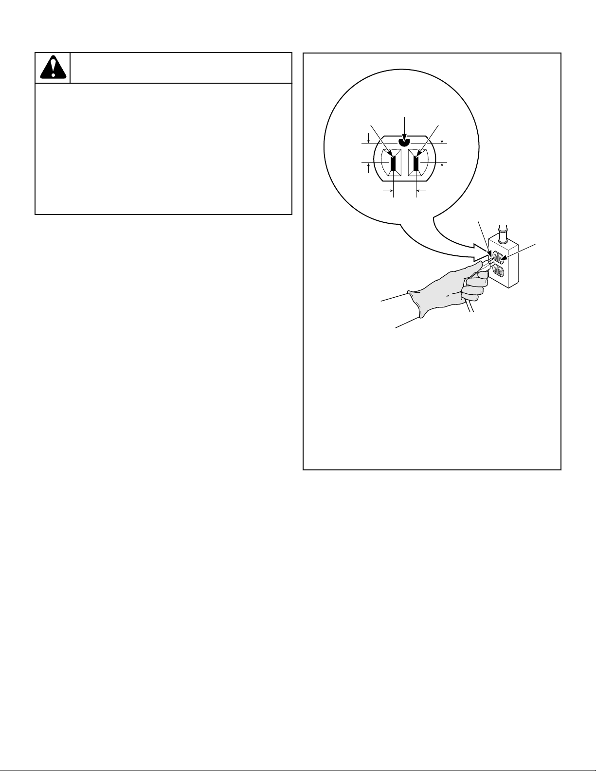
The dryer is designed to be operated on a separate branch, polar-
ized, three-wire, effective earth/ground, 120 Volt, 60 Hertz, AC
(alternating current) circuit protected by a 15 Ampere fuse,
equivalent fusetron or circuit breaker.
The three-prong earth/ground plug on the power cord should be
plugged directly into a polarized three-slot effective earth/ground
receptacle rated 120 Volts AC (alternating current) 15 Amps. Re-
fer to Figure 32 to determine correct polarity of the wall recepta-
cle.
Plug Cord Into Separately Fused 15 Amp Circuit
TLW2287N_SVG
6
8
7
2
1 3
5
4
1. L1
2. Earth/Ground
3. Neutral
4. Round Earth/Ground Plug
5. Neutral Side
6. 0 V.A.C.
7. 120 ± 12 V.A.C.
8. 120 ± 12 V.A.C.
Figure 32
Earth/Ground Information
This appliance must be properly connected to protective earth/
ground. In the event of malfunction or breakdown, the earth/
ground will reduce the risk of electric shock by providing a path
of least resistance for electric current.
The dryer is equipped with a cord having an equipment earth/
ground conductor and a three-prong earth/ground plug. The
three-prong earth/ground plug on the power cord should be plug-
ged directly into a polarized three-slot effective earth/ground re-
ceptacle rated 110/120 Volts AC (alternating current) 15 Amps.
Installation
©
Copyright, Alliance Laundry Systems LLC -
DO NOT COPY or TRANSMIT
29
Part No. D516906ENR1
WARNING
This unit is equipped with a three-prong (earth/
ground) plug for your protection against shock haz-
ard and should be plugged directly into a protective
earth/ ground three-prong receptacle. Do not cut or
remove the earth/ground prong from this plug.
W823
WARNING
Improper connection of the equipment earth/ground
conductor can result in a risk of electric shock.
Check with a qualified electrician or service person if
you are in doubt as to whether the dryer is properly
connected to a protective earth/ground.
W886
Do not modify the plug provided with the dryer – if it will not fit
the outlet, have a proper outlet installed by a qualified electrician.
NOTE: Have a qualified electrician check the polarity of
the wall receptacle. If a voltage reading is measured
other than that illustrated, the qualified electrician
should correct the problem.
Do not operate other appliances on the same circuit.
WARNING
To reduce the risk of an electric shock or fire, DO
NOT use an extension cord or an adapter to connect
the dryer to the electrical power source.
W037
Recheck Steps
Refer to Installer Checklist on the back cover of this manual and
make sure that dryer is installed correctly.
Check Heat Source
Electric Dryers
1. Close the loading door and start the dryer in a heat setting (re-
fer to the operation instructions).
2. After the dryer has operated for three minutes, the exhaust air
or exhaust pipe should be warm.
Gas Dryers
IMPORTANT: This operation is to be conducted by
qualified personnel only.
1. To view the burner flame, remove the lower front panel of the
dryer.
2. Close the loading door and start the dryer in a heat setting (re-
fer to the operation instructions). The dryer will start, the ig-
niter will glow red and the main burner will ignite.
IMPORTANT: If all air is not purged out of gas line,
gas igniter may go off before gas is ignited. If this
happens, after approximately two minutes igniter
will again attempt gas ignition.
IMPORTANT: If igniter does not light, make sure gas
is turned on.
3.
After either dryer has operated for approximately five mi-
nutes, observe burner flame through lower front panel.
4. Adjust the air shutter to obtain a soft, uniform blue flame. (A
lazy, yellow-tipped flame indicates lack of air. A harsh, roar-
ing, very blue flame indicates too much air
.) Adjust the air
shutter as follows:
a. Loosen the air shutter lockscrew.
b. Turn the air shutter to the left to get a luminous yellow-
tipped flame, then turn it back slowly to the right to obtain
a steady, soft blue flame.
c. After the air shutter is adjusted for proper flame, tighten
the air shutter lockscrew securely.
5. Reinstall the lower front panel.
WARNING
To reduce the risk of serious injury or death, low-
er front panel must be in place during normal op-
eration.
W158
6. After either dryer has operated for approximately three mi-
nutes, exhaust air or exhaust pipe should be warm.
Installation
©
Copyright, Alliance Laundry Systems LLC -
DO NOT COPY or TRANSMIT
30
Part No. D516906ENR1
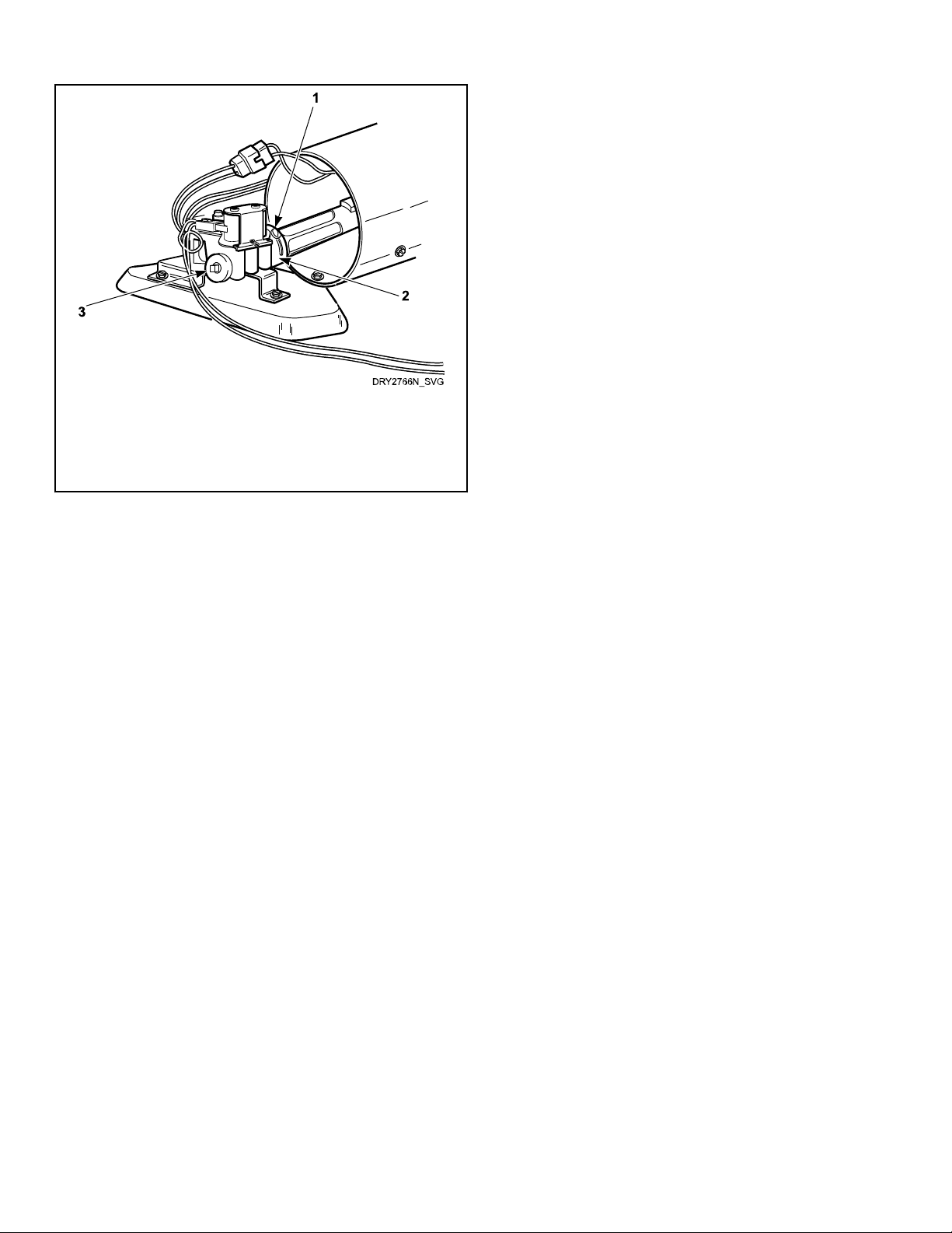
1. Air Shutter Lockscrew
2. Air Shutter
3. 1/8 in. [3.1 mm] Pipe Plug (For checking manifold pres-
sure)
Figure 33
Installation
©
Copyright, Alliance Laundry Systems LLC -
DO NOT COPY or TRANSMIT
31
Part No. D516906ENR1
Vending
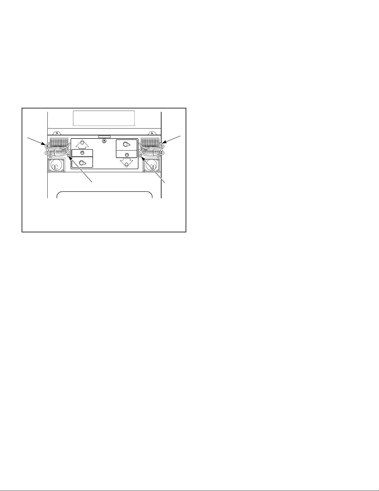
Coin Slide Guards
Using sheet metal screws from accessories bag (located in lower
cylinder), install coin slide guards (located in accessories bag in
lower cylinder) to front of dryer’s control cabinet. Refer to Fig-
ure 34 .
PUSH TO START
IN USE
IN USE
PUSH TO START
FABRIC SELECTOR
FABRIC SELECTOR
PERM PRESS
NORMAL
DELICATE
FLUFF
(NO HEAT)
PERM PRESS
NORMAL
DELICATE
FLUFF
(NO HEAT)
D784I_SVG
1
1
2
2
1. Coin Slide Guard
2. Sheet Metal Screws
Figure 34
NOTE: Coin slides and coin drawers are shown for il-
lustration only. You must obtain them locally.
Coin Slide Control
Power-Up Mode
Shortly after power is applied to the dryer, the control will flash
once to indicate the machine is ready to be used. If a cycle was
running previously, the control will blink and then stay lit, indi-
cating there is still time remaining from the previous cycle. If the
control was not previously running a cycle, the control will be in
Ready Mode.
Ready Mode
In Ready Mode, the control waits for the vend to be satisfied be-
fore entering Start Mode.
Start Mode
In Start Mode, the vend has been satisfied, but the Start button
has not been pressed. The IN USE LED will be lit. The timer will
not count down until the Start button is pressed.
Run Mode
In Run Mode, the control is running a cycle. The IN USE LED is
lit.
Door Open Mode
In Door Open Mode, the control turns off the heater and motor
when the door is opened during a run cycle. The timer will con-
tinue to count down time and the IN USE LED is lit.
End of Cycle Mode
In End of Cycle Mode, a cycle is complete and the IN USE LED
is off. The control remains in this mode until the door is opened
or additional vend has been satisfied.
Top-Offs
Any time the control receives a coin slide pulse during a cycle it
will add the programmed dry time to the time currently remaining
in the cycle. The IN USE LED will flash briefly to indicate the
coin input. The maximum cycle time is 99 minutes. The control
will not add time beyond 99 minutes. The cool down time will
not change. If the control receives a coin slide pulse during cool
down it will exit cool down and start heating with the cycle time
equal to the programmed time.
Temperature Selector Switch
Drying temperature is selected using the Temperature Selector
Switch. Temperature options for cycles are NO HEAT
, LOW,
MEDIUM and HIGH.
Error Display Mode
The control enters Error Display Mode to display thermistor er-
rors. The heater is turned off, the IN USE LED flashes to indicate
the error (refer to paragraphs below), and the timer will continue
to count down time. The control remains in Error Display Mode
until the control senses the thermistor has returned to an accepta-
ble heating range, the cycle ends or machine is powered down.
Open Thermistor
If the control senses a temperature less than 0°F when the heat
has been on for at least three minutes it will set an open thermis-
tor error. The control will flash the IN USE LED twice separated
by a one and a half second pause. This sequence is repeated as
long as the Open Thermistor error is sensed.
Shorted Thermistor
If the control senses a temperature greater than 210 ± 4°F during
an active cycle it will set a Shorted Thermistor error. The control
will flash the IN USE LED three times separated by a one and a
half second pause. This sequence is repeated as long as the Short-
ed Thermistor error is sensed.
Setting Dry Time Dipswitches
There are two banks of dipswitches on the dryer control: Dips-
witch1 and Dipswitch2. Each bank has eight switches: Dips-
witch1, Switch 1-8 and Dipswitch2, Switch 1-8. Bank Dips-
witch1 configures machine definition. Bank Dipswitch2 config-
ures vended cycle definition. Refer to Table 7 and Table 8 for
dipswitch options.
Vending
©
Copyright, Alliance Laundry Systems LLC -
DO NOT COPY or TRANSMIT
32
Part No. D516906ENR1
NOTE: The control reads the dipswitch settings at pow-
er-up. The control must be powered down to change
the dipswitch settings.
NOTE: The control must be powered down for 10 sec-
onds before the dipswitch can be changed.
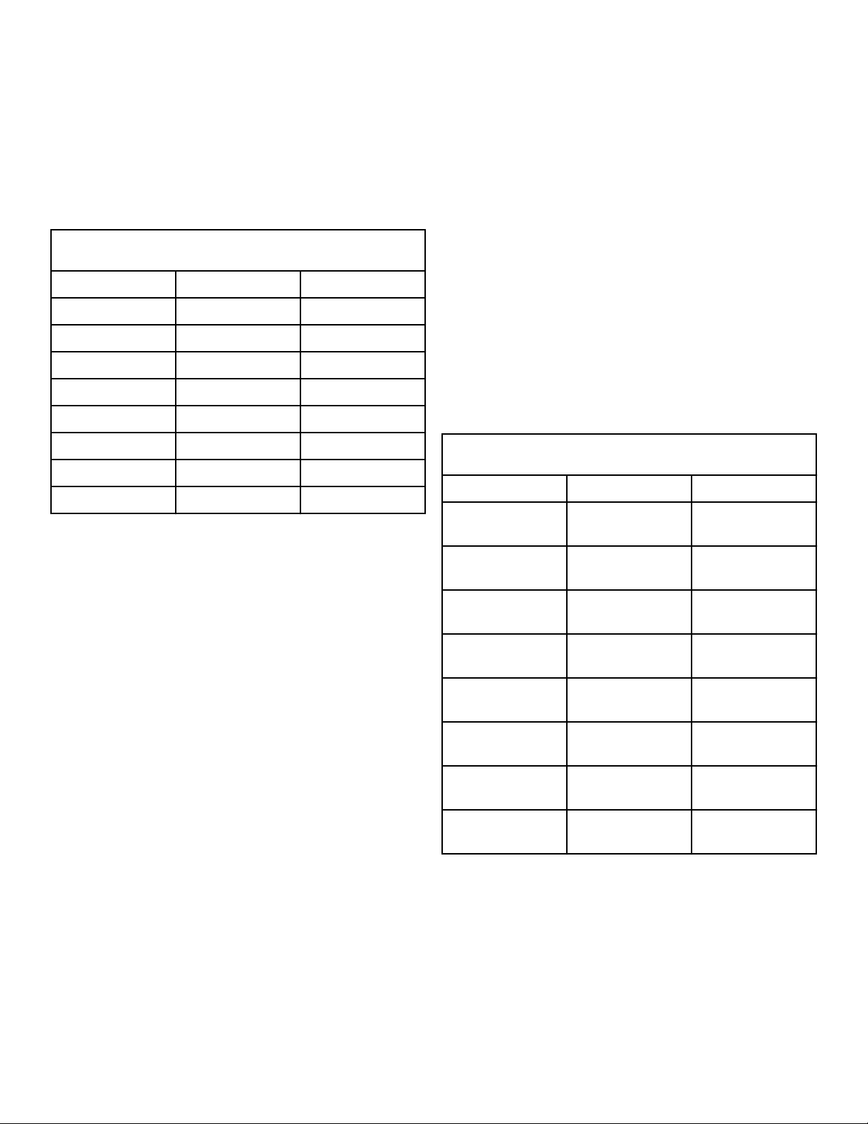
Dipswitch1 Bank
Refer to Table 7 .
Dipswitch1 Bank
Switch OFF ON
1 120 VAC supply 240 VAC supply
2 Unused Unused
3 Unused Unused
4 Unused Unused
5 Unused Unused
6 Unused Unused
7 Unused Unused
8 Unused Unused
Table 7
Dipswitch2 Bank
In Dipswitch2 bank, dipswitches 1 - 6 can be used to add addi-
tional dry time per coin pulse. This extends the total Dry Time
Per Vend amount. For each of these switches that are ON, time is
added in minutes. The maximum cycle length is 99 minutes. Heat
and cooldown time combined can never be longer than 99 mi-
nutes. Refer to Table 8 .
Dipswitch 7 specifies Cool-Down time for vended machines. The
Cool-Down time is three minutes when this switch is OFF, and
ten minutes when the switch is ON. For non-vended machines,
Cool-Down time is determined by the position of the Tempera-
ture Selector Switch.
Dipswitch 8 is used for the cycle reset on vended machines. If the
switch is OFF (default), the control will save the time left on a
cycle in case of a power failure. If the switch is ON, the control
will clear the cycle and return to Ready Mode if there is a power
failure. On non-vended machines, the control will clear any cycle
time and reset to Start Mode, regardless of the positions of these
dipswitches.
Dipswitch2 Bank
Switch OFF ON
1 Dry time per vend
[1]
Plus 1 minute dry
time per vend
2 Dry time per vend
[2]
Plus 2 minute dry
time per vend
3 Dry time per vend
[3]
Plus 4 minute dry
time per vend
4 Dry time per vend
[4]
Plus 8 minute dry
time per vend
5 Dry time per vend
[5]
Plus 16 minute dry
time per vend
6 Dry time per vend
[6]
Plus 32 minute dry
time per vend
7 Short Cool-Down
time
Long Cool-Down
time
8 Save cycle time on
long powerfail
Clear cycle time on
long powerfail
Table 8
Resetting Cycle Time to Zero
To remove any cycle time that may have accumulated on the con-
trol during setup, the cycle time on the control can be reset to
zero.
To reset the time, unplug the dryer and set dipswitch 8 to ON po-
sition. Restore power to the dryer for 10 seconds and once again
unplug dryer. Set dipswitch 8 to OFF position and restore power
to the dryer.
Vending
©
Copyright, Alliance Laundry Systems LLC -
DO NOT COPY or TRANSMIT
33
Part No. D516906ENR1

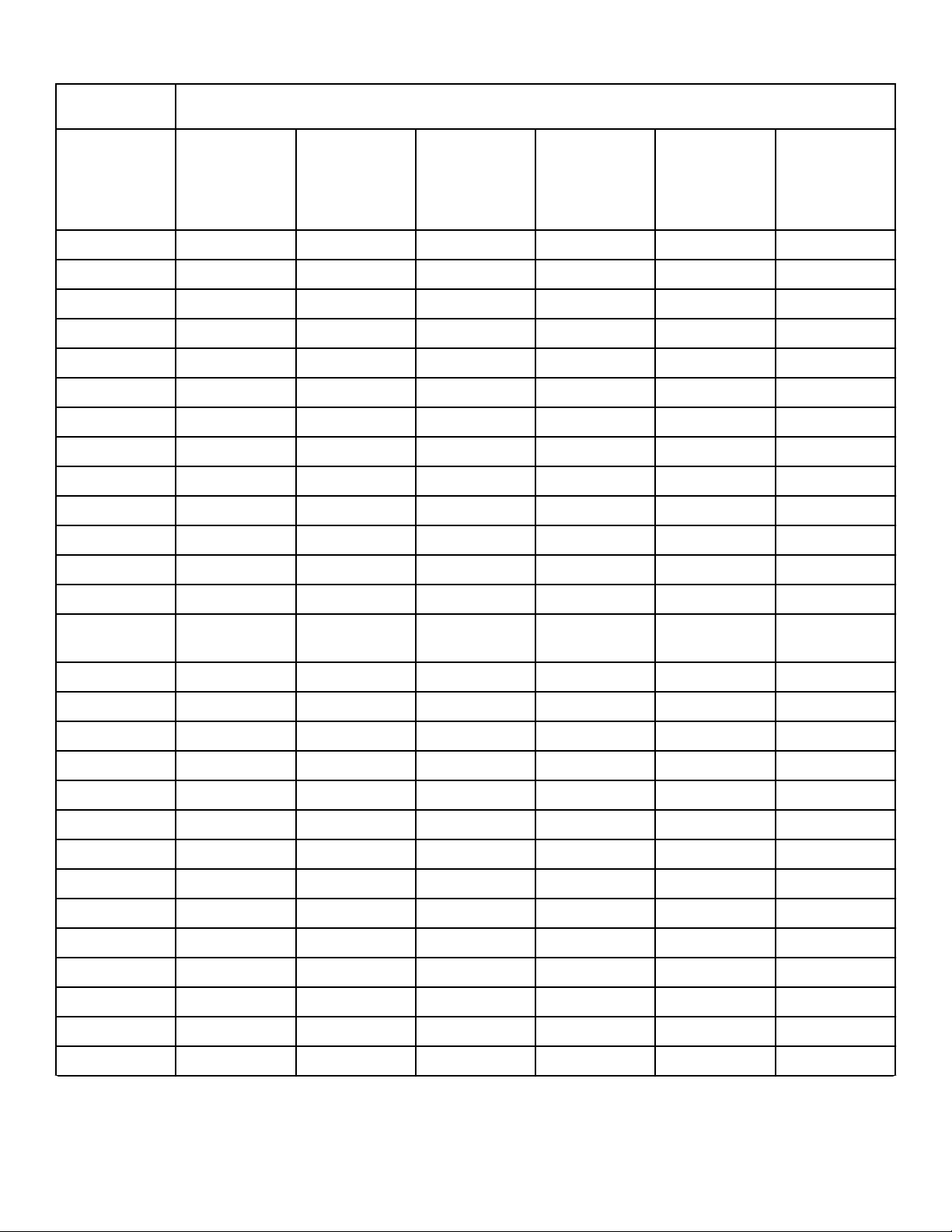
Dipswitch Settings
Heat Switch Number
Heat Time
Per Coin
Pulse (in mi-
nutes) 1 2 3 4 5 6
1 OFF OFF OFF OFF OFF OFF
2 ON OFF OFF OFF OFF OFF
3 OFF ON OFF OFF OFF OFF
4 ON ON OFF OFF OFF OFF
5 OFF OFF ON OFF OFF OFF
6 ON OFF ON OFF OFF OFF
7 OFF ON ON OFF OFF OFF
8 ON ON ON OFF OFF OFF
9 OFF OFF OFF ON OFF OFF
10 ON OFF OFF ON OFF OFF
11 OFF ON OFF ON OFF OFF
12 ON ON OFF ON OFF OFF
13 OFF OFF ON ON OFF OFF
14 ON OFF ON ON OFF OFF
15 OFF ON ON ON OFF OFF
16 ON ON ON ON OFF OFF
17 OFF OFF OFF OFF ON OFF
18 ON OFF OFF OFF ON OFF
19 OFF ON OFF OFF ON OFF
20 ON ON OFF OFF ON OFF
21 OFF OFF ON OFF ON OFF
22 ON OFF ON OFF ON OFF
23 OFF ON ON OFF ON OFF
24 ON ON ON OFF ON OFF
25 OFF OFF OFF ON ON OFF
26 ON OFF OFF ON ON OFF
27 OFF ON OFF ON ON OFF
28 ON ON OFF ON ON OFF
Table 9 continues...
Vending
©
Copyright, Alliance Laundry Systems LLC -
DO NOT COPY or TRANSMIT
34
Part No. D516906ENR1
Heat Switch Number
Heat Time
Per Coin
Pulse (in mi-
nutes) 1 2 3 4 5 6
29 OFF OFF ON ON ON OFF
30 ON OFF ON ON ON OFF
31 OFF ON ON ON ON OFF
32 ON ON ON ON ON OFF
33 OFF OFF OFF OFF OFF ON
34 ON OFF OFF OFF OFF ON
35 OFF ON OFF OFF OFF ON
36 ON ON OFF OFF OFF ON
37 OFF OFF ON OFF OFF ON
38 ON OFF ON OFF OFF ON
39 OFF ON ON OFF OFF ON
40 ON ON ON OFF OFF ON
41 OFF OFF OFF ON OFF ON
42 (preset at fac-
tory)
ON OFF OFF ON OFF ON
43 OFF ON OFF ON OFF ON
44 ON ON OFF ON OFF ON
45 OFF OFF ON ON OFF ON
46 ON OFF ON ON OFF ON
47 OFF ON ON ON OFF ON
48 ON ON ON ON OFF ON
49 OFF OFF OFF OFF ON ON
50 ON OFF OFF OFF ON ON
51 OFF ON OFF OFF ON ON
52 ON ON OFF OFF ON ON
53 OFF OFF ON OFF ON ON
54 ON OFF ON OFF ON ON
55 OFF ON ON OFF ON ON
56 ON ON ON OFF ON ON
Table 9 continues...
Vending
©
Copyright, Alliance Laundry Systems LLC -
DO NOT COPY or TRANSMIT
35
Part No. D516906ENR1
Heat Switch Number
Heat Time
Per Coin
Pulse (in mi-
nutes) 1 2 3 4 5 6
57 OFF OFF OFF ON ON ON
58 ON OFF OFF ON ON ON
59 OFF ON OFF ON ON ON
60 ON ON OFF ON ON ON
61 OFF OFF ON ON ON ON
62 ON OFF ON ON ON ON
63 OFF ON ON ON ON ON
64 ON ON ON ON ON ON
Table 9
Test Setting
When testing coin slide operation or other troubleshooting, set
dipswitch with this shorter cycle:
1. Unplug the machine power cord.
2. Record the machine control dipswitch settings. Then set them
all to the off position. Refer to Figure 1.
3. Plug in the machine and initiate a cycle.
NOTE: With all the control dipswitches off, the total
cycle time will be four minutes long.
4. Once all the testing is complete, unplug the machine and re-
set the dipswitches to their original settings.
5.
Plug in the machine.
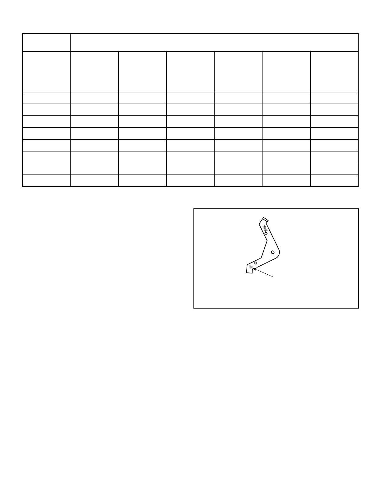
Slide Extension Assembly
1. Remove slide extension parts from parts accessories bag in-
cluded in unit.
2. Install extension lever with arm that has one star facing down.
Refer to Figure 35 .
TLW2160N_SVG
1
1. One Star
Figure 35
3. Install extension lever with rounded corner facing away from
extension bracket using shoulder bolt, flat washer and nut.
Refer to Figure 36 .
4. Install spring to extension bracket with hook facing down. In-
stall other end of spring to extension lever with hook facing
left while standing in front of unit. Refer to Figure 36 .
Vending
©
Copyright, Alliance Laundry Systems LLC -
DO NOT COPY or TRANSMIT
36
Part No. D516906ENR1
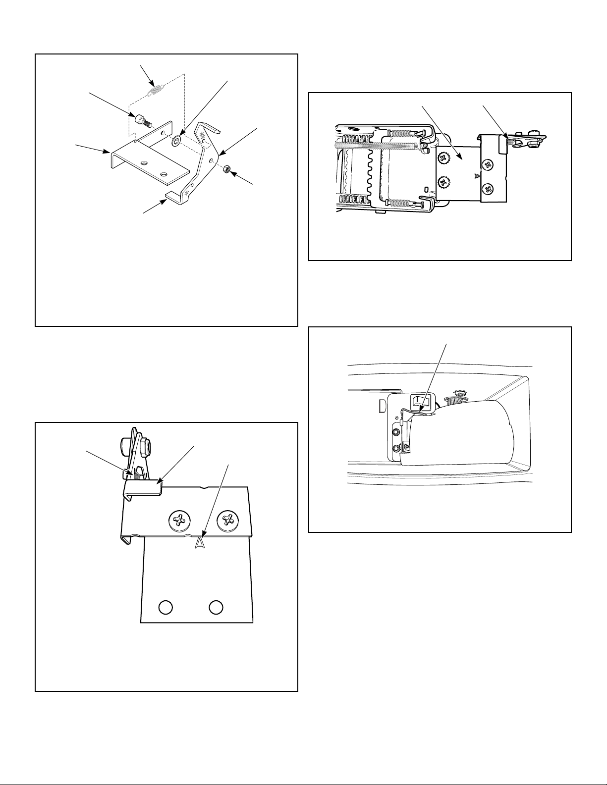
TLW1610K_SVG
7
6
5
4
3
2
1
1. Shoulder Bolt
2. Spring
3. Flat Washer
4. Rounded Corner
5. Nut
6. Extension Lever
7. Extension Bracket
Figure 36
5. Install extension bracket and lever assembly onto coin slide
bracket using two screws and locknuts. Refer to Figure 37 .
IMPORTANT: Install coin slide bracket with side
marked “A” facing up and toward extension bracket
and lever assembly. Refer to Figure 37 .
TLW2163N_SVG
3
2
1
1. Spring Installed
2. Extension Bracket and Lever Assembly
3. Coin Slide Bracket - Letter "A"
Figure 37
6. Install coin slide extension assembly onto top of coin slide us-
ing two remaining screws and lockwashers. Place lockwasher
under head of screws, above bracket “A”. Refer to Figure 38 .
TLW2164N_SVG
2
1
1. Coin Slide Extension Assembly
2. Spring Installed
Figure 38
7. Before installing coin slide and extension, make sure ground
wire is tucked under control shield to provide clearance for
coin slide. Refer to Figure 39 .
TLW2157N_SVG
1
1. Ground Wire Placement
Figure 39
Installing Coin Slide Assembly Into Meter Case:
Option One
1. Insert coins and partially extend coin slide.
2. Insert coin slide on its side through meter case opening. Then
rotate 90 degrees to its proper orientation.
3. Return coin slide and hook slide pins onto meter case.
4. Continue coin slide installation according to manufacturer’s
instructions.
5. Check to make sure coin slide is operating properly by insert-
ing coins and starting a cycle. The IN USE light will turn on,
or flash if it is already on, to indicate proper operation.
Vending
©
Copyright, Alliance Laundry Systems LLC -
DO NOT COPY or TRANSMIT
37
Part No. D516906ENR1

NOTE: To avoid long run-down time (45 minutes fac-
tory default) when testing operation, refer to Test
Setting section.
Installing Coin Slide Assembly Into Meter Case:
Option Two
1. Install coin slide according to manufacturer’s instructions.
2. Insert coins into coin slide and slowly push slide in. Stop be-
fore coins fall into coin box. This will allow installing exten-
sion through meter case service door opening.
3. Install slide extension onto top of coin slide using two screws.
Refer to Figure 38 .
4. Check to make sure coin slide is operating properly by insert-
ing coins and starting a cycle. The IN USE light will turn on,
or flash if it is already on, to indicate proper operation.
NOTE: To avoid long run-down time (45 minutes fac-
tory default) when testing operation, refer to Test
Setting section.
V
ending
©
Copyright, Alliance Laundry Systems LLC -
DO NOT COPY or TRANSMIT
38
Part No. D516906ENR1
Operation
Operation Instructions for Nonmetered
and Coin Slide Dryers
WARNING
To reduce the risk of fire, electric shock, or injury to
persons, read the IMPORTANT SAFETY INSTRUC-
TIONS before operating this appliance.
W727
IMPORTANT: Remove all objects from pockets such as
lighters and matches.
This appliance shall not be used to dry off solvents or dry clean-
ing fluids.
IMPORTANT: Before using dryer for the first time, use
an all-purpose cleaner, or a detergent and water solu-
tion, and a damp cloth to remove shipping dust from
inside of dryer drum.
IMPORTANT: Remove all sharp objects from laundry to
avoid tears and rips to items during normal machine
operation.
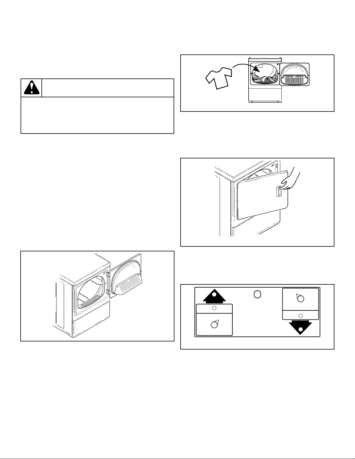
Clean Lint Filter
Clean lint filter before each use.
D608I_SVG
Figure 40
Load Laundry
1. Load clothes loosely into dryer drum (18.0 lbs. [8.2 Kg] max-
imum dry clothes load).
2. Add fabric softener sheet if desired.
IMPORTANT: To avoid damage to dryer, do not use
more than one fabric softener sheet per load.
D717I_SVG
Figure 41
Close Loading Door
1. Close loading door.
2. Dryer will not operate with the door open.
D688I_SVG
Figure 42
Determine Proper Dryer
The direction of the arrow indicates which dryer is being used.
DRY2224N_SVG
Figure 43
Set Fabric Selector
Select NORMAL for cottons, PERM PRESS for permanent
press, DELICATE for sensitive items or NO HEAT for items that
require no heat.
NOTE: Always follow manufacturer's care labels.
Operation
©
Copyright, Alliance Laundry Systems LLC -
DO NOT COPY or TRANSMIT
39
Part No. D516906ENR1
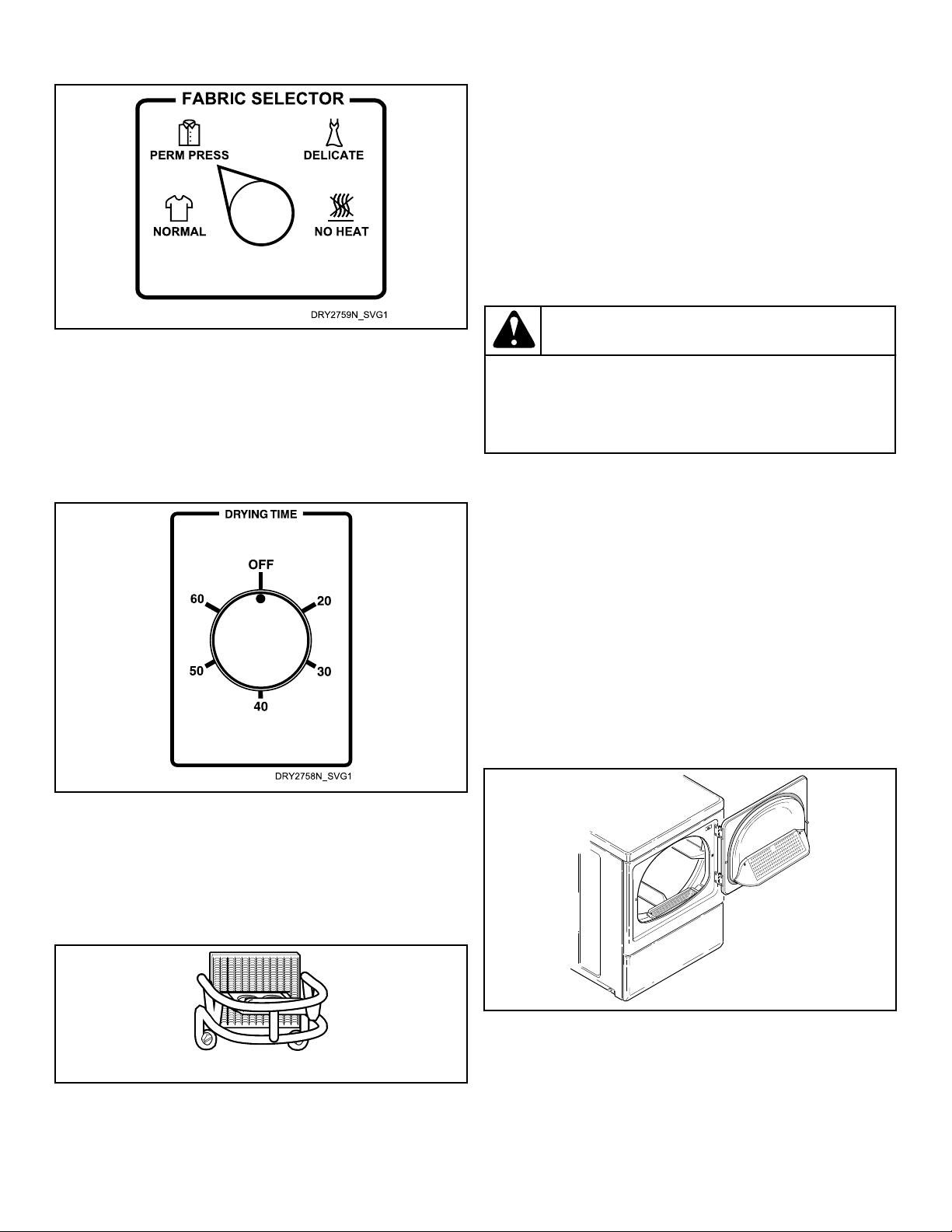
Figure 44
Start Dryer
Nonmetered Models
1. Rotate timer knob to desired time setting (up to 60 minutes).
2. Press the PUSH-TO-START button. IN USE light will come
on (indicating start of cycle).
Figure 45
Coin Slide Models
1. Place coin(s) in slide and carefully push in as far as possible
and then pull slide out as far as possible.
2. After IN USE light comes on (indicating start of cycle), press
the PUSH-TO-START button.
D363I_SVG
Figure 46
3. Remove knits when slightly damp because overdyring may
cause shrinkage. Do not tumble dry knit woolens.
Should dryer stop before cycle is completed, the motor overload
protector may have cycled. Refer to Maintenance section.
NOTE: This machine includes an extended tumble fea-
ture. Starting 20 minutes after a cycle ends, the cylin-
der will tumble for two minutes every hour without
heat, up to 18 hours or until door is opened.
Operation Instructions for MDC Dryers
WARNING
To reduce the risk of fire, electric shock, or injury to
persons, read the IMPORTANT SAFETY INSTRUC-
TIONS before operating this appliance.
W727
IMPORTANT: Remove all objects from pockets such as
lighters and matches.
This appliance shall not be used to dry off solvents or dry clean-
ing fluids.
IMPORTANT: Before using dryer for the first time, use
an all-purpose cleaner, or a detergent and water solu-
tion, and a damp cloth to remove shipping dust from
inside of dryer drum.
IMPORTANT: Remove all sharp objects from laundry to
avoid tears and rips to items during normal machine
operation.
Clean Lint Filter
Clean lint filter before each use.
D608I_SVG
Figure 47
Load Laundry
1. Load clothes loosely into dryer drum (18.0 lbs. [8.2 Kg] max-
imum dry clothes load).
2. Add fabric softener sheet if desired.
Operation
©
Copyright, Alliance Laundry Systems LLC -
DO NOT COPY or TRANSMIT
40
Part No. D516906ENR1
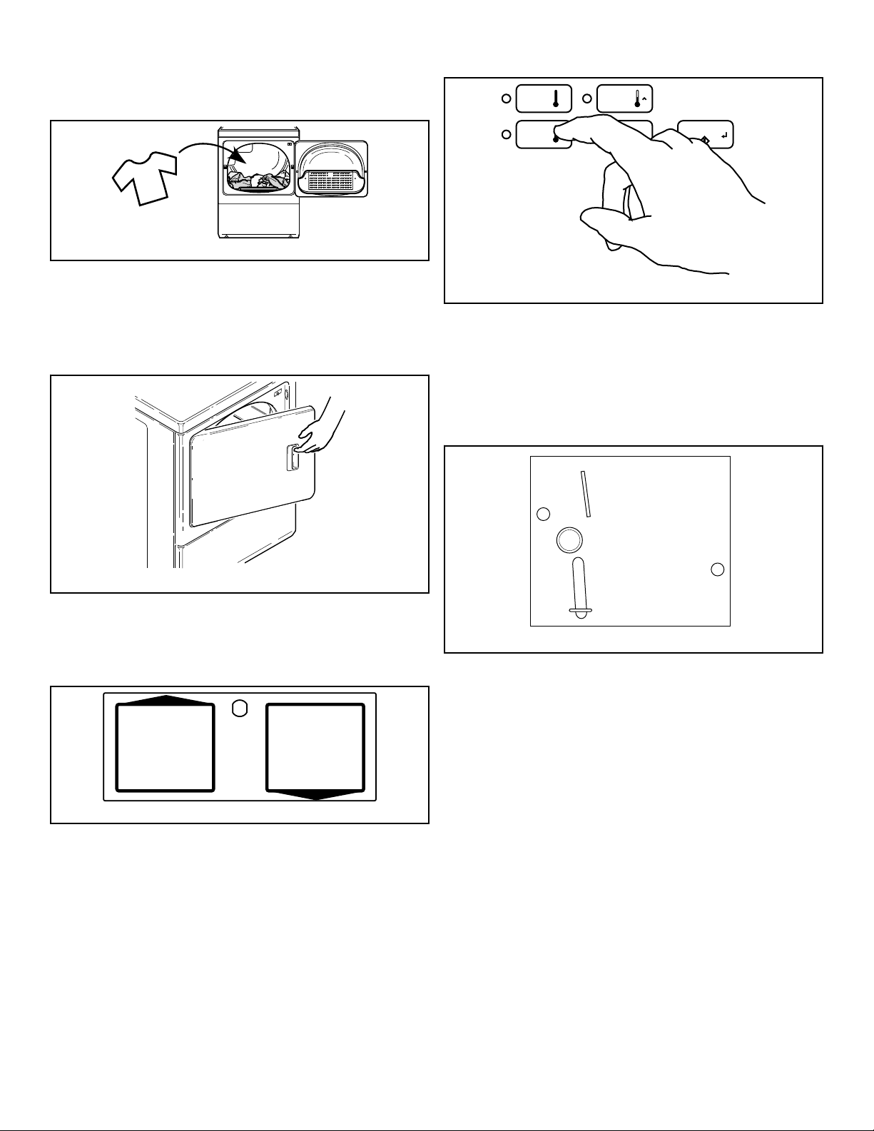
IMPORTANT: To avoid damage to dryer, do not use
more than one fabric softener sheet per load.
D717I_SVG
Figure 48
Close Loading Door
1. Close loading door.
2. Dryer will not operate with the door open.
D688I_SVG
Figure 49
Determine Proper Dryer
The direction of the arrow indicates which dryer is being used.
DRY2315N_SVG
Figure 50
Set Fabric Selector
Select HIGH TEMP, MED TEMP, LOW TEMP or DELICATES
by pushing touchpad.
NOTE: Always follow manufacturer's care labels.
DRY2688N_SVG
DELICATES
START
MED
TEMP
HIGH
TEMP
LOW
TEMP
Figure 51
Insert Coins or Card
To Insert Coins
1. Insert coin(s) in coin slot.
2. Check pricing as seen on digital display.
W387I_SVG
Figure 52
To Insert Card
Insert card into opening.
Operation
©
Copyright, Alliance Laundry Systems LLC -
DO NOT COPY or TRANSMIT
41
Part No. D516906ENR1
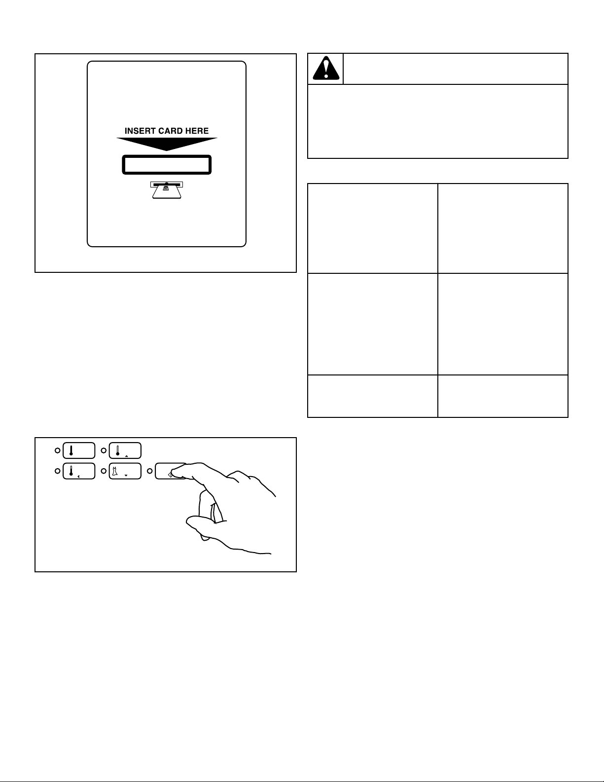
DRY2633N_SVG
Figure 53
Start Dryer
1. To start dryer, push START pad.
2. To stop dryer at any time, open the door.
3. To restart the dryer, close door and push START pad. Cycle is
completed when time remaining reaches 00 minutes.
If Additional Time Feature is turned on, additional dryer time
may be purchased at cycle start or while dryer is running.
Remove knits when slightly damp because overdrying may cause
shrinkage. Do not tumble dry knit woolens.
DRY2765N_SVG
DELICATES
START
MED
TEMP
HIGH
TEMP
LOW
TEMP
Figure 54
IMPORTANT: The final part of dryer cycle occurs with-
out heat (cool down cycle) to ensure that items in dryer
are left at a temperature that ensures that the items will
not be damaged.
WARNING
To prevent the risk of fire, never stop a dryer before
the end of the drying cycle unless all items are
quickly removed and spread out so that the heat is
dissipated.
W756
Indicator Lights
START START is lit whenever the
dryer is not in a cycle, the full
vend price has been satisfied
and the dryer door is closed.
When the START pad is press-
ed, the cycle will begin or re-
sume.
DRYING DRYING is lit to indicate that
one of the heated cycles
(HIGH TEMP, MED TEMP,
LOW TEMP or DELICATES)
is currently in operation. DRY-
ING will turn off at the end of
a heated cycle or when the
COOL DOWN cycle begins.
COOL DOWN COOL DOWN is lit whenever
the COOL DOWN portion of a
heated cycle is active.
Operation
©
Copyright, Alliance Laundry Systems LLC -
DO NOT COPY or TRANSMIT
42
Part No. D516906ENR1
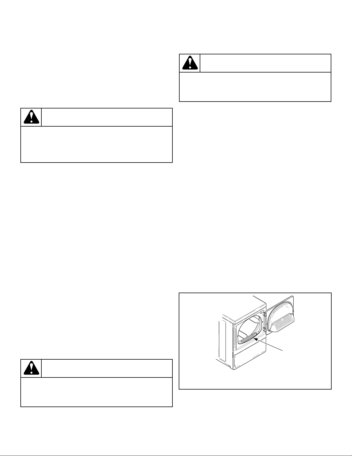
Maintenance
Lubrication
All moving parts are sealed in a permanent supply of lubricant or
are equipped with oilless bearings. Additional lubrication will not
be necessary.
Care of Your Dryer
WARNING
To reduce the risk of an electric shock, serious injury
or death, disconnect the electrical service to the dry-
er before cleaning the interior.
W132
Dryer Interior
Wipe the surfaces using a soft cloth and household cleaner or a
non-abrasive paste of powdered laundry detergent and hot water,
followed by a short heat cycle with a load of rags.
To remove crayon or ball point ink off the dryer drum, put the
heat on high and use old rags in the dryer to absorb the crayon or
ink. If unsuccessful, contact the appliance dealer. DO NOT use
any chemicals in the dryer.
IMPORTANT: The use of chlorine bleach for removing
any discolorations should be avoided because bleach
could damage the finish.
Cabinet
Wipe the dryer cabinet as needed. If detergent, bleach or other
washing products have been spilled on the dryer, wipe immedi-
ately. Some products will cause permanent damage if spilled on
the cabinet.
Control Panel
Use only a damp or sudsy cloth for cleaning the control panel.
Some spray pretreat products may harm the finish on the control
panel. DO NOT use products that contain alcohol on the control
panel.
Exhaust System
WARNING
To reduce the risk of electric shock, disconnect the
electrical service to the dryer before cleaning.
W043
WARNING
Any disassembly requiring the use of tools must be
performed by a suitably qualified service person.
W299
The exhaust duct should be inspected after one year of use and
cleaned if necessary by a qualified service person to remove any
lint build-up. Inspect and clean exhaust duct every one to two
years as required thereafter.
NOTE: This recommended maintenance is not covered
under the terms of the warranty.
The weather hood should be checked frequently to make sure the
dampers move freely, dampers are not pushed in and that nothing
has been set against them.
Keep dryer area clear and free from combustible materials, gaso-
line and other flammable vapors and liquids.
Do not obstruct the flow of combustion and ventilation air.
NOTE: Verify proper operation after servicing.
Lint Filter
CLEAN THE LINT FILTER BEFORE DRYING EACH LOAD.
(Refer to Figure 55 for lint filter location.) Cleaning the lint filter
is important because a layer or pad of lint on the filter will block
the flow of air through the dryer, thus reducing the efficiency of
the dryer. The clothes will take longer to dry and energy will be
wasted.
The lint filter may be washed if needed. Annually remove lint fil-
ter and screw to vacuum the duct under it.
D608I_SVG1
1
1. Lint Filter
Figure 55
Maintenance
©
Copyright, Alliance Laundry Systems LLC -
DO NOT COPY or TRANSMIT
43
Part No. D516906ENR1

Motor Overload Protector
The dryer’s motor overload protector stops the motor automati-
cally in the event of an overload. After cooling, the overload pro-
tector will reset itself. Dryer can be restarted by pressing the
START pad. If overload protector cycles again, remove the dryer
from use and call the service person to correct the problem.
For Energy Conservation
• Make sure the lint filter is always clean.
• Do not overload dryer.
• Do not overdry clothes.
• Remove items to be ironed while still damp.
• Large loads of similar fabrics dry the most efficiently
. How-
ever, dry permanent press in smaller loads to prevent wrin-
kling.
• Use the correct temperature FABRIC SELECTOR setting for
the type of fabric being dried.
• Locate your dryer so the exhaust duct is as short and straight
as possible.
• Do not open the door during the drying cycle.
• Plan to do your laundry on low humidity days; your clothes
will dry faster.
• Should you plan to dry several loads, do them one after anoth-
er, then you do not have to reheat the dryer unit’s interior
parts each time.
Maintenance
©
Copyright, Alliance Laundry Systems LLC -
DO NOT COPY or TRANSMIT
44
Part No. D516906ENR1

Troubleshooting
Try these troubleshooting tips before making a service call. They
may save you time and money.
Dryer Symptom Possible Cause/Solution
Dryer won’t start • Insert coin(s) or card, if required.
• For dryers equipped with a power cord, make sure the power
cord is plugged all the way into the electrical outlet.
• Make sure loading door is closed.
• Press START pad.
• Make sure the laundry room fuse(s) isn’t blown or loose, or
circuit breakers aren’
t open.
• The dryer itself does not have an electrical fuse. An electric
dryer has an electrical circuit with two fuses.
• Check if motor overload protector has cycled. Wait 10 mi-
nutes and try again.
Dryer won’t heat • Make sure the laundry room fuse(s) isn’t blown or loose, or
circuit breakers aren’t open.
• The dryer itself does not have an electrical fuse. An electric
dryer has an electrical circuit with two fuses.
• Make sure controls are in a HEAT setting.
• Gas dryer only – Make sure equipment and main gas line
valve is turned on.
• Check exhaust duct to outside to see if it is kinked, blocked or
needs cleaning.
• Check weather hood to make sure flapper moves freely, has
not been pushed in or has not been blocked.
Dryer doesn’t dry clothes satisfactorily • Check exhaust duct to outside to see if it is kinked, blocked or
needs cleaning.
• Check weather hood to make sure flapper moves freely, has
not been pushed in or has not been blocked.
• Clean the lint filter.
• Make sure the load isn’t too small. Small loads may not tum-
ble properly or dry evenly.
• Check load being dried. Heavy items dried with lightweight
items will not dry as quickly as the rest of the load.
Dryer is noisy • Check dryer for foreign objects (nails, coins, bobby pins, met-
al, plastic toys, etc.). Remove items from dryer.
• Make sure dryer is level. Uneven leveling can cause vibra-
tion.
• Normal operating sounds include the heat source going on
and off and the humming of air moving through the dryer and
exhaust system.
Table continues...
Troubleshooting
©
Copyright, Alliance Laundry Systems LLC -
DO NOT COPY or TRANSMIT
45
Part No. D516906ENR1

Dryer Symptom Possible Cause/Solution
Clothes are too wrinkled • Check heat setting. Overdrying can cause wrinkling.
• Check load size. Large loads may not tumble properly and
may cause wrinkling.
Clothes have odor • Check room for odors before drying clothes. Any odor (fried
foods, paint, varnish, cleaners, burning wood, etc.) will trans-
fer to clothing as the dryer draws air from the room.
• Ventilate room before drying clothes.
Troubleshooting
©
Copyright, Alliance Laundry Systems LLC -
DO NOT COPY or TRANSMIT
46
Part No. D516906ENR1
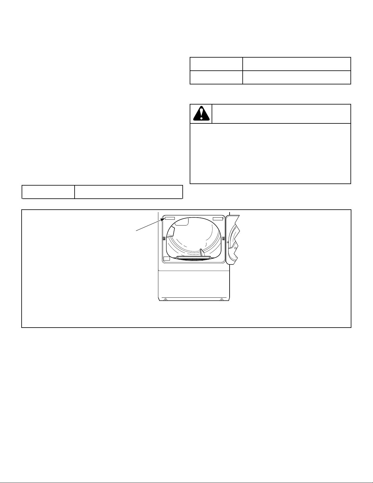
Contact Information
If service is required, contact the nearest Factory Authorized
Service Center.
If you are unable to locate an authorized service center or are un-
satisfied with the service performed on your unit, contact:
Alliance Laundry Systems
Shepard Street
P.O. Box 990
Ripon, WI 54971-0990
U.S.A.
www.alliancelaundry.com
Phone: +1 (920) 748-3121
When calling or writing about your unit, PLEASE GIVE THE
MODEL AND SERIAL NUMBERS. The model and serial num-
bers are located on the serial plate. The serial plate will be in the
location shown in Figure 56 .
Date Purchased
T
able continues...
Model Number
Serial Number
Please include a copy of your bill of sale and any service receipts
you have.
WARNING
To reduce the risk of serious injury or death, DO NOT
repair or replace any part of the unit or attempt any
servicing unless specifically recommended in the
user-maintenance instructions or in published user-
repair instructions that you understand and have the
skills to carry out.
W329
If replacement parts are required, contact the source from where
you purchased your unit or call +1 (920) 748-3950 for the name
and address of the nearest authorized parts distributor.
DRY2527N_SVG
1
1. Serial Plate
Figure 56
Contact Information
©
Copyright, Alliance Laundry Systems LLC -
DO NOT COPY or TRANSMIT
47
Part No. D516906ENR1
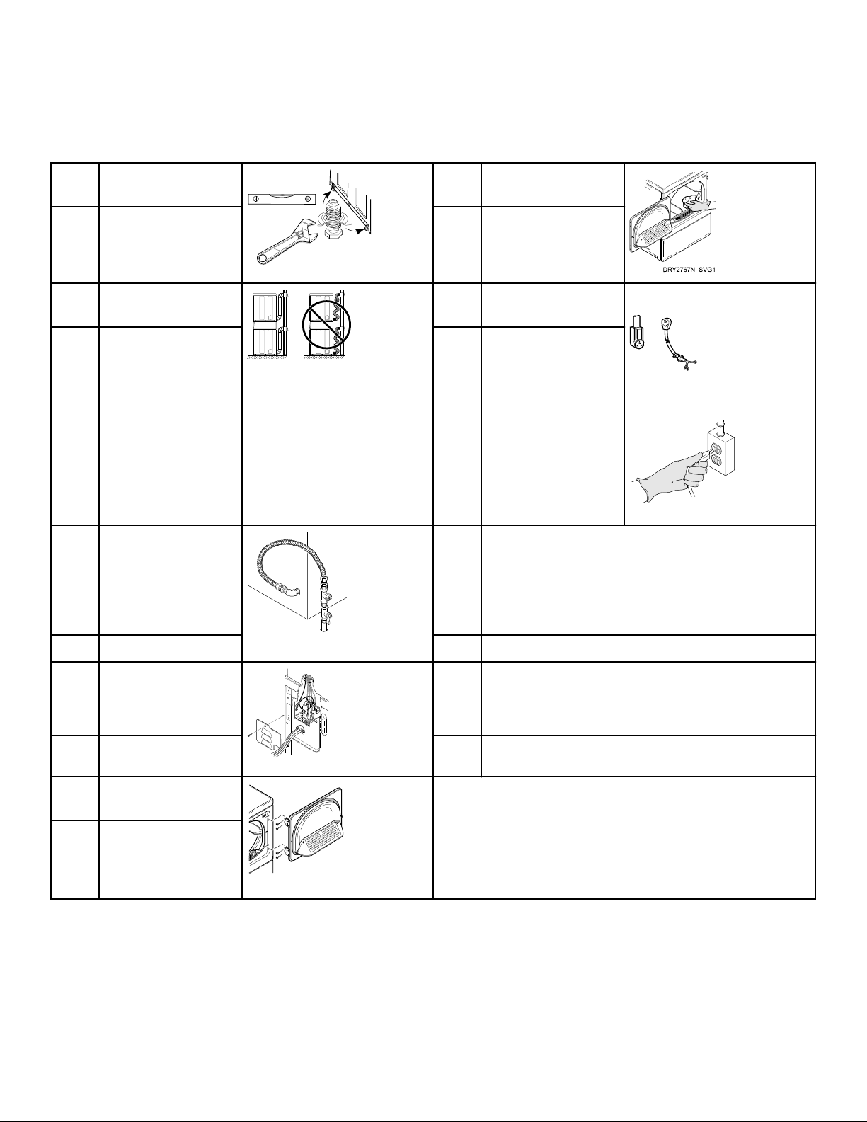
Installer Checklist
Fast Track for Installing the Dryer
1 Position and Level the
Dryer.
DRY2634N_SVG
6 Wipe Out Inside of
Dryer.
CHECK CHECK
2 Connect Dryer Exhaust
System.
DRY2540N_SVG1
7 Plug In the Dryer. Electric
D275I_SVG1
Gas
TLW2289N_SVG
CHECK CHECK
3 GAS ONLY
• Connect Gas Sup-
ply Pipe.
• Check for Gas
Leaks.
D233I_SVG1
8 Recheck Steps.
CHECK CHECK
4 ELECTRIC ONLY
• Connect Electrical
Cord.
D699I_SVG1
9 Start and Run Dryer in Heat Setting to Verify Dryer is
Heating.
CHECK CHECK
5 Reverse Door, if De-
sired.
D675I_SVG1
CHECK
Refer to the manual for more detailed information
Installer Checklist
©
Copyright, Alliance Laundry Systems LLC -
DO NOT COPY or TRANSMIT
48
Part No. D516906ENR1