Loading ...
Loading ...
3
TABLE OF CONTENTS
1. I NSTALL DUCTWORK ................................................................................................................................................................3
2. PREPARE THE INSTALLATION .....................................................................................................................................................4
3. P
REPARE THE HOOD ............................................................................................................................................................4-5
4. INSTALL GLASS PANEL (WITHOUT GLASS MODELS ONLY) ..................................................................................................................5
5. INSTALL THE ADAPTER/DAMPER .................................................................................................................................................6
6. I
NSTALL THE HOOD .................................................................................................................................................................7
7. C
ONNECT WIRING ..................................................................................................................................................................7
8. REINSTALL BLOWER WHEEL AND BOTTOM PANEL ........................................................................................................................... 7
9. REINSTALL HYBRID FILTERS ......................................................................................................................................................8
10. LED LIGHTING ......................................................................................................................................................................8
11. CARE ..................................................................................................................................................................................8
12. OPERATION ..........................................................................................................................................................................9
13. WIRING DIAGRAM.................................................................................................................................................................10
14. SERVICE PA RT S ................................................................................................................................................................... 11
15. WARRANTY ........................................................................................................................................................................12
1. INSTALL DUCTWORK
Plan where and how the ductwork will be installed.
The ducting from this fan to the outside of the building has a strong effect on the air flow, noise and energy use of the fan. Use the shortest,
straightest duct routing possible for best performance, and avoid installing the fan with smaller ducts than recommended. Insulation around
the ducts can reduce energy loss and inhibit mold growth. Fans installed with existing ducts may not achieve their rated airflow. Refer to
the table at the botom of this page to help you plan the most efficient installation.
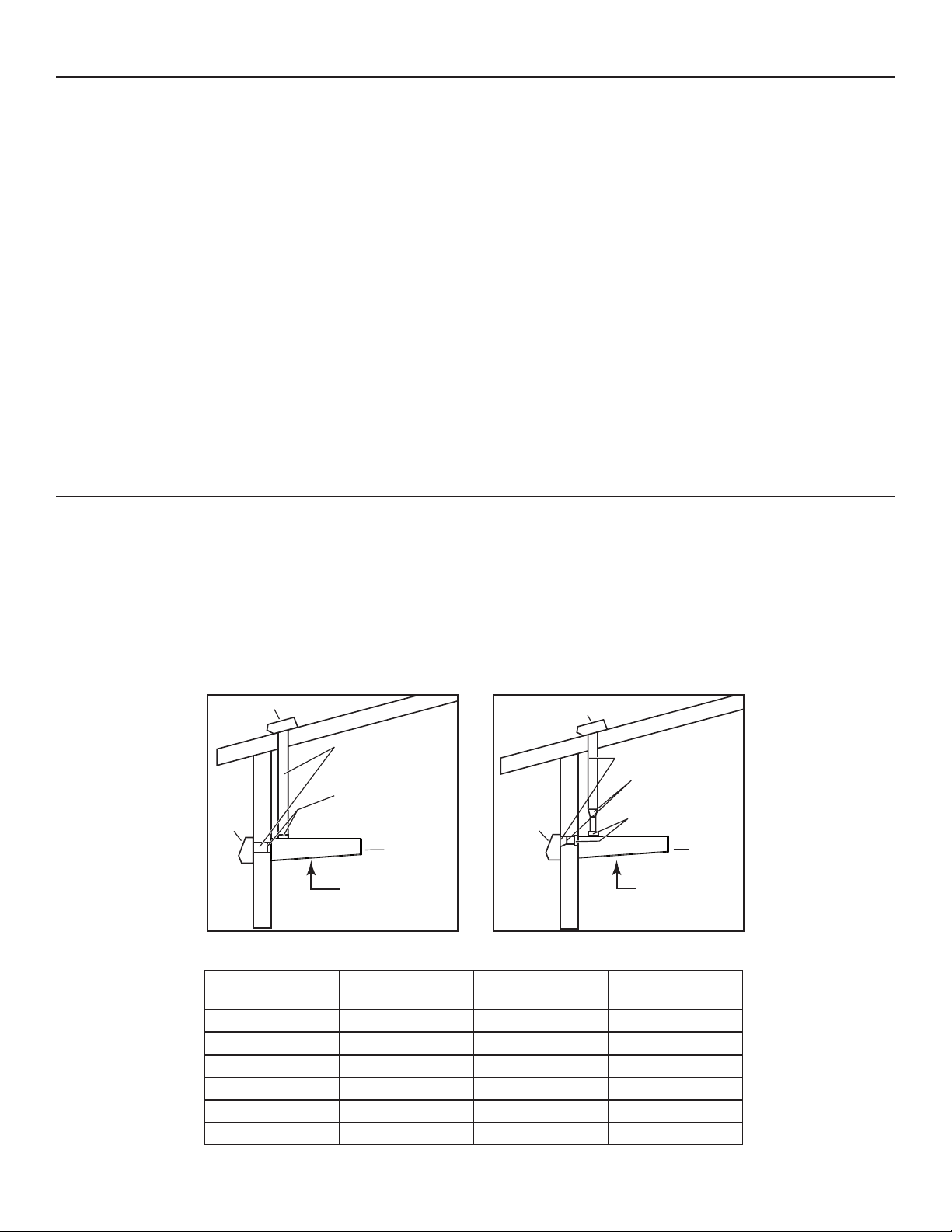
Install wall or roof cap; once done, ensure there is no leak in house insulation. Connect metal ductwork to cap and work back towards the
hood location. If 6” round ducts are installed, use a 3¼” x 10” to 6” transition positionned, if possible, 18” away from the adapter/damper.
Use 2” metal foil duct tape to seal the joints.
We recommend to install the hood at a minimum distance of 24” from an electric range and of 30” from a gas range.
Distances over 30” are at the installer and users discretion.
HOOD
3¼" X 10" DUCT
ROOF CAP
WALL
CAP
HH0142A
24" MINIMUM ABOVE
COOKING
SURFACE
(30" FOR GAS RANGE)
3¼" X 10"
A
DAPTER/DAMPER
HOOD
6" ROUND DUCT
ROOF CAP
WALL CAP
3¼" X 10" TO 6"
R
OUND TRANSITION
HH0222A
3¼" X 10"
A
DAPTER/DAMPER
24" MINIMUM ABOVE
COOKING
SURFACE
(30" FOR GAS RANGE)
3 ¼” X 10” MAXIMUM
DUCT LENGHT
6” ROUND MAXIMUM
DUCT LENGHT
ROOF OR WALL CAP
WITH DAMPER
ELBOW(S)*
(90° AND/OR 45°)
60
FT.- 1 0
50
FT.- 1 1
40
FT.- 1 2
- 50
FT.1 0
- 40
FT.1 1
- 30
FT.1 2
M
AXIMUM DUCT LENGHTS RECOMMENDED TO ACHIEVE 80% EXHAUST EFFICIENCY
*STANDARD ELBOWS
WITH 1” INTERNAL
RADIUS.
Loading ...
Loading ...
Loading ...