Loading ...
Loading ...
Loading ...
28
INSTALLATION
Check the appliance is electrically safe and gas sound when you have nished.
Installation of this range must conform with local codes or, in
the absence of local codes, with the National Fuel Gas Code,
ANSI Z223.1-latest edition.
In Canada
The range must be installed in accordance with the current
CGA Standard CAN/CGA-B149 – Installation Codes for Gas
Burning Appliances and Equipment and/or local codes.
In the Commonwealth of Massachusetts
This product must be installed by a licensed plumber or
gas tter when installed within the Commonwealth of
Massachusetts.
A “T” handle type manual gas valve must be installed in the
gas supply line to this appliance.
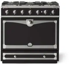
Gas supply requirements
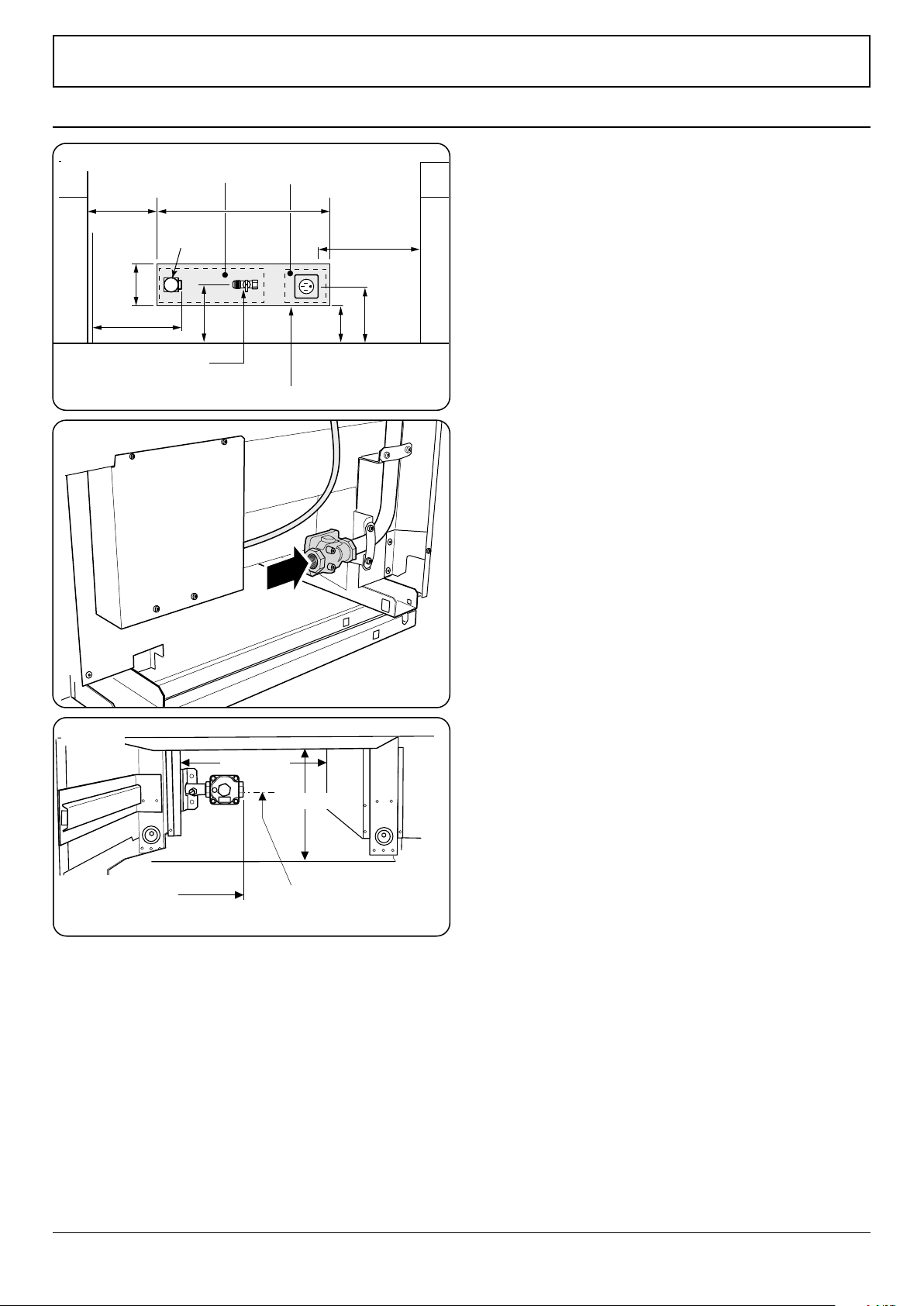
Recommended gas pipe outlet locations are shown in
Fig. 10.1, Fig. 10.2 and Fig. 10.3.
Provide adequate Gas Supply
Prior to installation, ensure that the local distribution
conditions (nature of the gas and gas pressure) and the
adjustment of the appliance are compatible.
A conversion kit for LP gas (Propane) is supplied with the
range. When converted to LP gas, a pressure of 10’’ of water
column (2.49 kPa) is required.
Make sure you are supplying your range with the correct type
of gas.
If the range is to be used on LP gas, a qualied LP installer
must convert it. We recommend that the range be converted
before installation. This must be done before the range can
be used on LP gas.
For proper operation, the pressure of natural gas supplied to
the regulator must be between 4½’’ and 13’’ of water column
(1.12–3.24 kPa).
For LP gas, the pressure supplied must be between 10’’ and
13’’ of water column (2.49–3.24 kPa).
When checking for proper operation of the regulator, the
inlet pressure must be at least 1’’ (0.25 kPa) greater than the
operating (manifold) pressure as given above.
The pressure regulator located at the inlet of the range
manifold must remain in the supply line regardless of
whether natural or LP gas is being used.
A exible metal appliance connector used to connect the
range to the gas supply line should have an I.D. of ½’’ and be
5 feet in length for ease of installation.
Area accessible through drawer
Gas shut-o valve
Gas supply
zone
Electrical
supply zone
Side of
range
Range gas
inlet
17”
6”
6”
7”
16”
6”
9”
4”
ArtNo280-0074 Connection fron Rear
8¾” (22.2 cm) from
the side of the range
6“ (15.2 cm) from the oor
with range at lowest point
10¼” (26 cm)
7¾” (19.7 cm)
Fig. 10.1
Fig. 10.2
Fig. 10.3
10. Gas connection
Loading ...
Loading ...
Loading ...