Loading ...
Loading ...
Loading ...
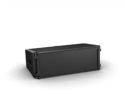
Installation Guide - ShowMatch
TM
DeltaQ
TM
Array Loudspeakers English 11
Technical Specifications
pro.Bose.com
Array Rigging
ShowMatch DeltaQ array loudspeakers are shipped with integrated link-bar rigging hardware. The rigging
system is designed to allow fast setup of typical concert-touring or fixed-installation arrays of up to 24
full-range or 18 subwoofer modules while maintaining a 10:1 Safety Factor when used with optional Bose®
ShowMatch Array Frame Rigging Accessories.
Note: Always confirm safe working load limits with exact array configurations, pitch angles, and connection
points using either Bose Modeler® or Bose Array Tool software.
For details on installing ShowMatch modules to array frames, please refer to the ShowMatch DeltaQ Array
Rigging Frames document, which is included in the package of array frames and is also available for
download at pro.Bose.com.
Note: Bose ShowMatch loudspeakers and rigging accessories are intended for installation by professional
installers only!
Note: All lifting operations require two individuals positioned on each side of the loudspeaker.
Painting the Enclosure
ShowMatch modules, with the end caps removed, can be painted using a solvent-based spray paint such
as KRYLON®. For best results, ensure the surface is dry and free of oils and debris. Always test a small
inconspicuous area before spraying the entire product. Remove grills and paint separately. Verify that paint
does not clog perforations in metal grill. Mask woofers, manifold slots, and rear input panel to ensure paint
does not cover these areas.
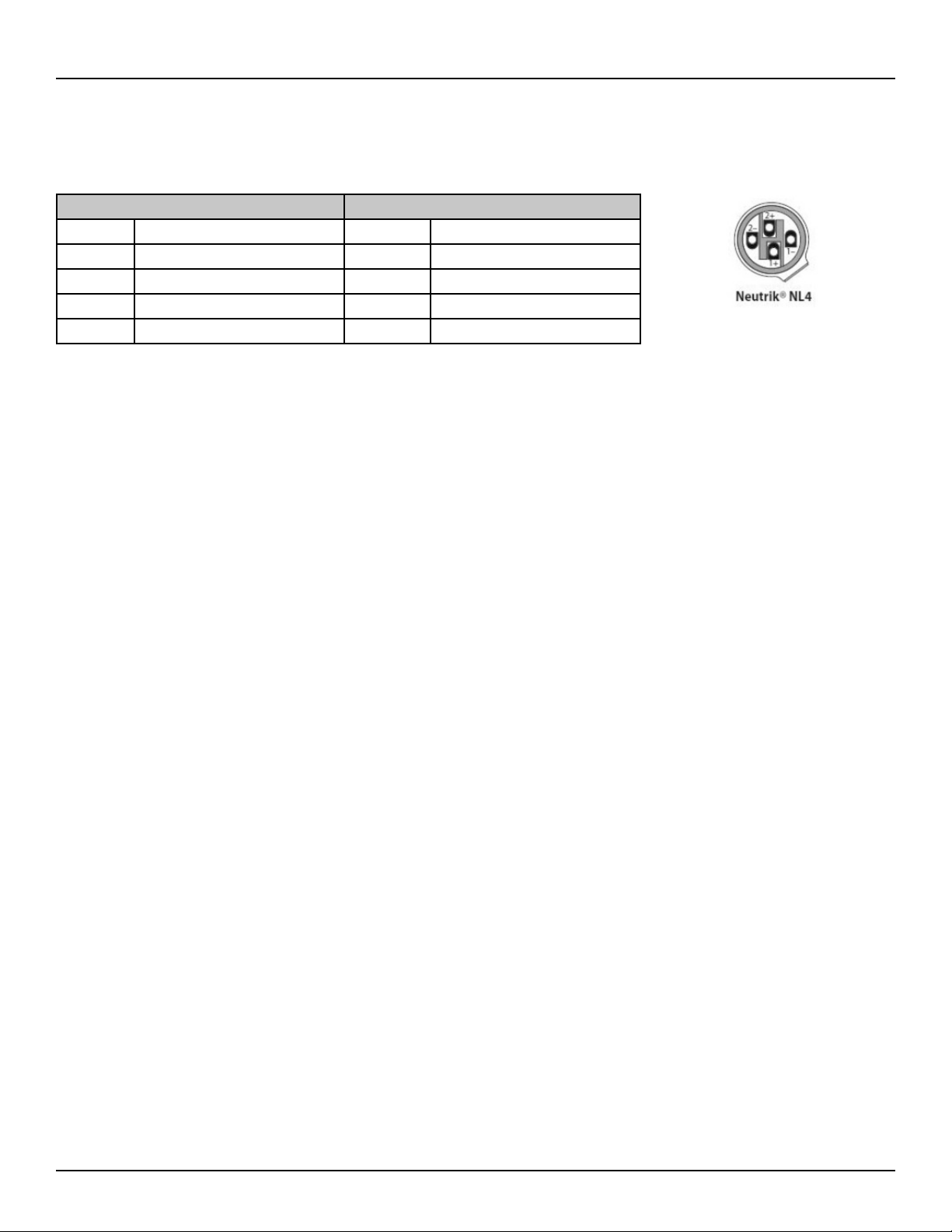
Connector Wiring
ShowMatch full-range and subwoofer modules are each equipped with two (2) Neutrik® NL4 connectors
wired in parallel to allow loop-through connections. Full-range module connectors are wired to provide
separate amplifier channels to the high-frequency (HF) and low-frequency (LF) transducers. See table below.
Full-Range Subwoofer
NL4 Pin Driver Section NL4 Pin Driver Section
1+ LF drivers - positive 1+ sub - positive
1- LF drivers - negative 1- sub - negative
2+ HF drivers - positive 2+ not used
2- HF drivers - negative 2- not used
Loading ...
Loading ...
Loading ...