
Loading ...
Loading ...
Loading ...
15
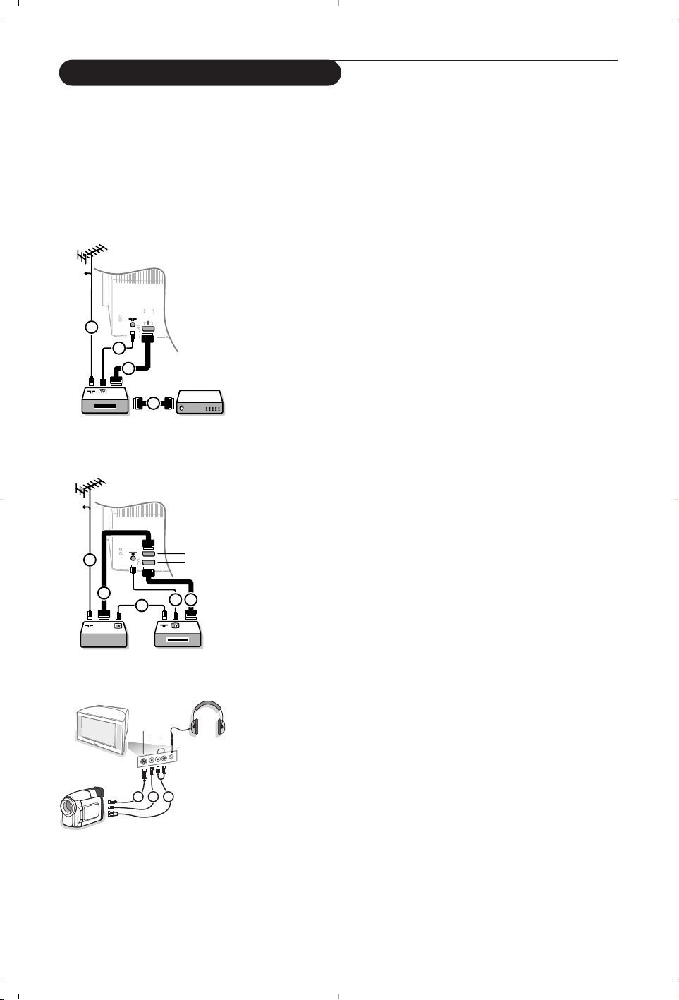
Recorder (VCR-DVD+RW)
Connect the aerial cables 1, 2 and, to obtain the optimum
picture quality, eurocable 3 as shown.
If your recorder does not have a euroconnector, the only
possible connection is via the aerial cable.You will therefore
need to tune in your recorder’s test signal and assign it
programme number 0 or store the test signal under a
programme number between 90 and 99, see Manual installation,
p. 6. See the handbook of your recorder.
Decoder and Recorder
Connect a eurocable 4 to your decoder and to the special
euroconnector of your recorder. See also the recorder
handbook. See Decoder, p. 8. You can also connect your
decoder directly to
EXT. 1 or 2 with a eurocable.
Other equipment (satellite receiver, decoder, DVD, games, etc.)
& Connect the aerial cables 1, 2 and 3 as shown (only if
your peripheral has TV aerial in-/output).
Connect your equipment with a eurocable 4 or 5 to one of
the euroconnectors
EXT.1, 2 or 3 to obtain a better picture
quality.
é Look for the test signal of your peripheral in the same way as
you do for a recorder.
“ Make a selection in the Setup, Source menu, p. 8.
Side connections
Camera or Camcorder
& Connect your camera or camcorder as shown.
é Connect to VIDEO 2 and AUDIO L 3 for mono
equipment. For stereo equipment also connect
AUDIO R 3.
S-VHS quality with an S-VHS camcorder is obtained by
connecting the S-VHS cables with the
S-VIDEO input 1 and
AUDIO inputs 3.
Do not connect cable 1 and 2 at the same time.This may cause
picture distortion !
Headphone
& Insert the plug into the headphone socket L as shown.
é Press ¬ on the remote control to switch off the internal
loudspeakers of the TV.
The headphone impedance must be between 8 and 4000 Ohm.The
headphone socket has a 3.5 mm jack.
In the Sound menu select
Headphone volume to adjust the
headphone volume.
CABLE
1
4
2
EXT.
2
3
CABLE
1
2
1
EXT.
2
4
5
3
Connect Peripheral Equipment
A
U
D
IO
VIDEO
S•VIDEO
1 2 3
There is a wide range of audio and video equipment that can be connected to your TV.
The following connection diagrams show you how to connect them.
Depending on the versions, the TV set is equipped with 2 or 3 SCART connectors EXT1, EXT2 and EXT3
located on the rear.
Note:
EXT. 1 can handle CVBS and RGB, EXT. 2 CVBS and Y/C, EXT. 3 CVBS and RGB. It is preferred to connect
peripherals with RGB output to
EXT. 1 or EXT. 3 as RGB provides a better picture quality.
If your recorder is provided with the Easylink function, it should be connected to
EXT. 2 to benefit from the EasyLink
functionality.
Loading ...
Loading ...
Loading ...