Loading ...
Installation and Operating Instructions
Dimplex Air Curtain - Single Phase Conversion Kit - CAB1PN
Suitable for use with the CAB10E, CAB15E & DAB10E (Surface & Recessed)
08/19538/0 Issue 4
THESE INSTRUCTIONS SHOULD BE READ CAREFULLY AND RETAINED FOR FUTURE REFERENCE
IMPORTANT SAFETY ADVICE
ENSURE THE APPLIANCE IS EARTHED.
This work should only be carried out by a competent
electrician.
Always disconnect the supply before working on the
product.
Ensure the supply cables are of adequate current
carrying capacity and are protected by a suitable
fuse.
Ensure all wiring is fi xed clear of all moving parts and
heat sources.
This kit is not designed for use with DAB15 models.
This conversion kit consists of:
8 x 100mm x 2.5mm tie wraps
4 x Moss Plastic tie wrap clips
2 x Neutral link cable
1 x Live link cable
The instructions for the conversion kit should be
read in conjunction with the ‘Dimplex Air Curtain’
Instructions. All ‘Safety Advice’ to be heeded before
fi tting this kit.
General
The CAB10E, CAB15E and DAB10E are primarlity
designed for 400V~ 3P&N 50Hz operation, however in
the instance where it is not possible to utilise a 3-phase
supply, the units can be de-rated to a ½ heat stiing for
operation via a 230V~ 1P&N 50Hz supply.
Procedure
1. remove the outlet grille assemblies and, where
necessary, the bottom panel and inlet grille to gain
access to the element banks and terminal blocks as
shown in Fig. 1 below.
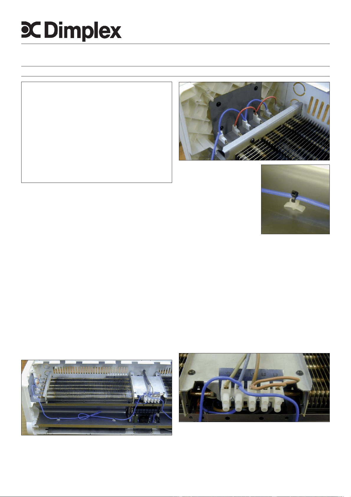
2. Remove the fi rst half heat (H1) star connection link
cable from both sides of each elmenet bank (Fig. 2 shows
the bottom red (H1)) star connection link cable replaced
with the supplied neutral star connection link cable.
3. Fix the push on clips (two on
either side) to the inside of the
pressure plate as shown in Fig.
1 (the supplied push on clips
are a press fi t into their fi xing
holes (ø3.5mm). Proceed
to attach the neutral star link
connection cable to the push
on clips using the tie wraps as
shown in Fig. 3 below.
Note: Due to extra cable length (for CAB15E) it is
necessary to loop the slack cable in the pressure plate and
secure it using a supplied tie wrap as shown in Fig. 1.
4. Connect the brass ferrule end of the neutral link cable
into the N of the terminal block (along with the Neutral of
the single phase supply) as shown in Fig. 4.
5. Also shown in Fig. 4 is the supplied (brown) Live link
cable, this should be linked from L1 (with connection of
Live from single phase supply) to L2 & L3.
The earth cable is connected as normal within the
terminal block (ensure the supply cable is fi xed
appropriately within the back panel using the correct
sized gland).
6. Check all switch settings operate, as stated within
the evaluation table (overleaf). Note: H2 should still be
connected (as per remote switch connection instruction
manual) even though it will not be utilised (this still allows
a ½ heat setting when switched to full heat rather than no
heat at all).
Figure 1.
Figure 2.
Figure 3.
Figure 4.
BLUE
RED
Loading ...