Loading ...
Loading ...
Loading ...
5
ENGLISH
2. Positioning
Speaker Installation
801 D4, 802 D4 and 803 D4 are intended to be oor
mounted only and are supplied on wheels to aid
with positioning. It is important to ensure that they
stand rmly on the oor using the spike feet supplied
whenever possible.
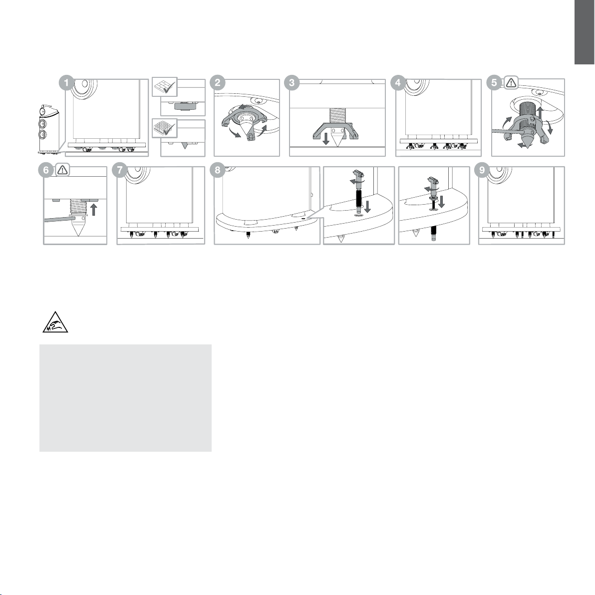
Important Safety Notice
Sharp spikes, do not touch.
Note:Ifyouareinstallingtheproductonverythick
carpetsuchthatthewheelspreventthespeaker
fromrestingsolelyonthespikes,youmaywish
toremovethewheelsfromthebottomoftheplinth,
usinga5mmhex(Allen)key.Duetotheweightof
thespeakers,removalofthewheelsshould
onlybeundertakenbytwopeople–onetotiltthe
speakersidewaysandholditwhiletheother
removesthewheels.Werecommendthatasuitable
wedgeorblockisusedtopreventtheloudspeaker
accidentallyfallingtotheoorwhilstremovingor
rettingthewheels.
Once the speakers are in the correct position the
spikes, inbuilt in the plinth, can be released. Placing
your ngers in the gap between the plinth and the oor
locate the four spike cups. If your speaker is positioned
on a hard oor leave the spike cups in place to protect
the ooring. If your speaker is on carpet remove the
four spike cups, which are held magnetically, and retain
them for future use. This will reveal the spike ready for
it to be lowered into position.
Directly above each spike/spike cup you will feel a
three pronged locking nut. Using your ngers, spin the
locking nut, as directed above in step 2, to lower the
spike/spike cup towards the oor. If the locking nut is
too tight to turn, insert the supplied metal bar into the
hole at the end of one of the prongs and turn; releasing
the locking nut (see above illustration).
As the spike/spike cup meets the oor continue to
turn the locking nut lifting the speaker off its wheels.
Repeat this process with all four spikes/spike cups
and adjust the height to ensure the speaker rests
rmly without rocking.
To lock the spikes/spike cups in place insert the metal
bar into one of the four holes in the spikes. Using the
metal bar to stop the spike turning, rotate the locking
nut, as directed above in step 5. Once the locking nut
is released, remove the metal bar and continue to spin
the locking nut returning it to its locked position in the
plinth. To ensure the locking nut is tightly locked in
place reinsert the metal bar into one of the four holes
on the spike. With the metal bar holding the spike in
position, use your ngers to turn the locking nut until it
can no longer rotate. Repeat this for each spike.
Once the spikes are locked in position, the stabilisers
should be tted to minimise the risk of the loudspeaker
being accidentally knocked over. The stabiliser should
be threaded through the plinth and lowered into
position by using the T45 tool to turn the stabiliser
clockwise until the rubber tip rests on the oor.
The stabiliser should not be excessively tightened in
order to avoid the spikes being unweighted, which
would reduce stability and impair performance. Once
the stabilisers are lowered into position the caps can
be threaded into the top of the stabiliser and gently
tightened with the T45 tool until they rest in the recess
in the plinth.
If the speaker needs to be repositioned the stabiliser
caps must be removed, the stabilisers raised and
the spikes returned back into the plinth before the
product is moved. To do this use the T45 tool to
remove the stabiliser caps by turning anticlockwise,
then use the T45 tool to raise the stabilisers by turning
anticlockwise. Once the stabilisers are raised, insert
the metal bar into one of the four holes in the spike,
with the metal bar holding the spike in position, use
your ngers to turn the locking nut, as directed above
in step 2, releasing it. Then continue to spin the locking
nut until it can no longer rotate; this will ensure the
locking nut and spike are engaged. Now turn the
locking nut, as directed above in step 3, and the spike
will start ascending back into the plinth. Once the spike
has been returned to the plinth replace the spike cup (if
removed) and the speaker can now be repositioned.
Loading ...
Loading ...
Loading ...