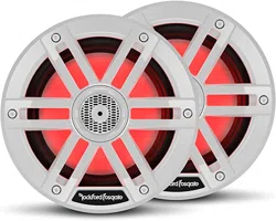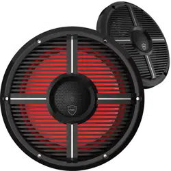
M1-6
M1-6B
M1-65
M1-65B
M1-8
M1-8B
Installation & Operation
ELEMENT READY™ SPEAKERS
2
Dear Customer,
Congratulations on your purchase of the world’s finest brand of audio
products. At Rockford Fosgate we are fanatics about musical reproduc-
tion at its best, and we are pleased you chose our product. Through
years of engineering expertise, hand crasmanship and critical testing
procedures, we have created a wide range of products that reproduce
music with all the clarity and richness you deserve.
For maximum performance we recommend you have your new Rock-
ford Fosgate product installed by an Authorized Rockford Fosgate
Dealer. Please read your warranty and retain your receipt and original
carton for possible future use.
Great product and competent installations are only a piece of the
puzzle when it comes to your system. Make sure that your installer is
using 100% authentic installation accessories from Rockford Fosgate in
your installation. Rockford Fosgate has everything from RCA cables and
speaker wire to power wire and battery connectors. Insist on it! Aer
all, your new system deserves nothing but the best.
To add the finishing touch to your new Rockford Fosgate image, order
your Rockford accessories, which include everything from T-shirts to
hats.
Visit our web site for the latest information on all Rockford products
;
www.rockfordfosgate.com
or, in the U.S. call 1-800-669-9899 or FAX 1-800-398-3985. For all
other countries, call +001-480-967-3565 or FAX +001-480-966-
3983.
Table of Content
If, aer reading your manual, you still have questions regarding
this product, we recommend that you see your Rockford Fosgate
dealer. If you need further assistance, you can call us direct at
1-800-669-9899. Be sure to have your serial number, model num-
ber and date of purchase available when you call.
Safety
This symbol with “WARNING” is intend-
ed to alert the user to the presence of
important instructions. Failure to heed
the instructions could result in severe
injury or death.
This symbol with “CAUTION” is intend-
ed to alert the user to the presence of
important instructions. Failure to heed
the instructions could result in injury
or unit damage.
• To prevent injury and damage to the unit, please read and
follow the instructions in this manual.
• If you feel unsure about installing this system yourself, have
it installed by a qualified Rockford Fosgate technician.
• Before installation, disconnect the battery negative (-)
terminal to prevent damage to the unit, fire and/or possible
injury.
Introduction
©2019 RockfordCorporation. All Rights Reserved. ROCKFORD FOSGATE, PUNCH
®
and associated logos where applicable are registered trademarks of
Rockford Corporation in the United States and/or other countries. All other trademarks are the property of their respective owners. Specifications sub-
ject to change without notice.
2 Introduction
3 Specifications
4 Diagrams
5 Wiring
6 Installation Considerations
Mounting
7-19 Additional Languages
French
Spanish
German
Italian
20 Limited Warranty Information
PRACTICE SAFE SOUND
Continuous exposure to sound pressure levels over 100dB may
cause permanent hearing loss. High powered auto sound systems
may produce sound pressure levels well over 130dB. Use common
sense and practice safe sound.
PRATIQUEZ UNE ÉCOUTE SANS RISQUES
Une exposition continue à des niveaux de pression acoustique
upérieurs à 100 dB peut causer une perte d’acuité auditive
permanente. Les systèmes audio de forte puissance pour auto
peuvent produire des niveaux de pression acoustique bien au-delà
de 130 dB. Faites preuve de bon sens et pratiquez une écoute sans
risques
PRACTIQUE EL SONIDO SEGURO
El contacto continuo con niveles de presión de sonido superiores
a 100 dB puede causar la pérdida permanente de la audición. Los
sistemas de sonido de alta potencia para automóviles pueden
producir niveles de presión de sonido superiores a los 130 dB. Aplique
el sentido común y practique el sonido seguro.
PRAKTIZIEREN SIE SICHEREN SOUND
Fortgesetzte Geräuschdruckpegel von über 100 dB können beim
Menschen zu permanentem Hörverlust führen. Leistungsstarke
Autosoundsysteme können Geräuschdruckpegel erzeugen, die weit
über 130 dB liegen. Bitte wenden Sie gesunden Menschenverstand an
und praktizieren Sie sicheren Sound.
OSSERVATE LE REGOLE DEL SUONO SENZA PERICOLI
La costante esposizione a livelli di pressione acustica al di sopra dei
100dB possono causare la perdita permanente dell’udito. I sistemi
audio ad alta potenza possono produrre livelli di pressione acustica
ben superiori ai 130dB. Si consiglia il buon senso e l’osservanza delle
regole del suono senza pericoli
3
Specifications
Model
M1-6
M1-6B
M1-65
M1-65B
M1-8
M1-8B
Nominal Size
6”
(152.4mm)
6.5”
(165mm)
8”
(203.2mm)
Description
2-Way 2-Way 2-Way
Nominal Impedance (Ohms)
4Ω 4Ω 4Ω
Frequency Response (Hz)*
42-22kHz 38-22kHz 35-22kHz
Power Handling - Watts (RMS/Peak) 75/300 75/300 150/600
Sensitivity
89dB 90dB 92dB
Grille/Trim Ring
YES YES YES
LED Current Draw 0.25 Amps 0.25 Amps 0.25 Amps
Recommended Fused Rating For
LED’s (not included)
1 Amp 1 Amp 1 Amp
LED Voltage Range 9-16 Volts 9-16 Volts 9-16 Volts
VERIFIED WITH KLIPPEL
To adorn the ‘Verified with Klippel’ mark, the qualifying company’s loudspeaker engineering personnel must be trained
and certified by Klippel prior to using the three separate Klippel systems to design, develop and test. Rockford Fosgate
has made the investment in Klippel to deliver the best possible speakers and subwoofers to their customers.
*
Rockford Fosgate determines its rated frequency response range at -6 dB below its nominal sensitivity
at upper and lower extents of a speaker’s output.

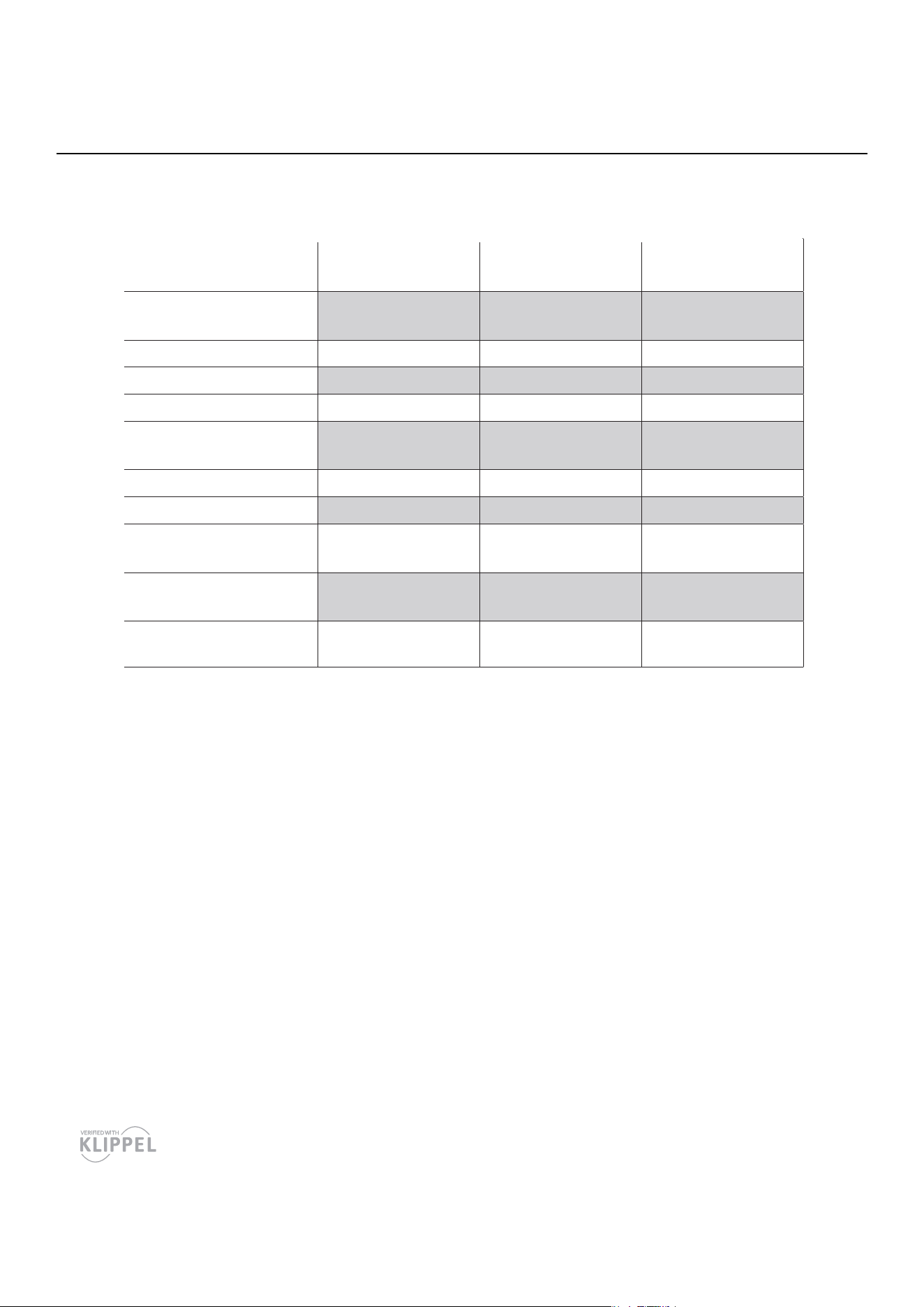
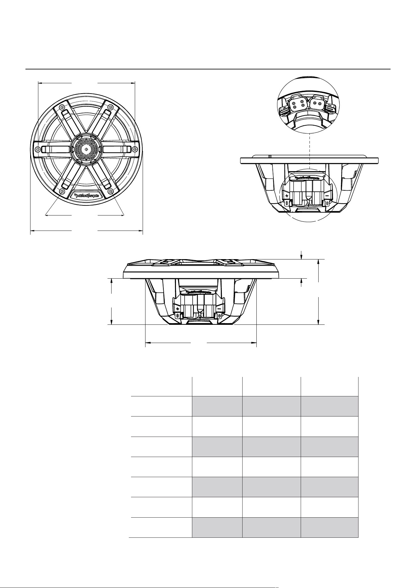
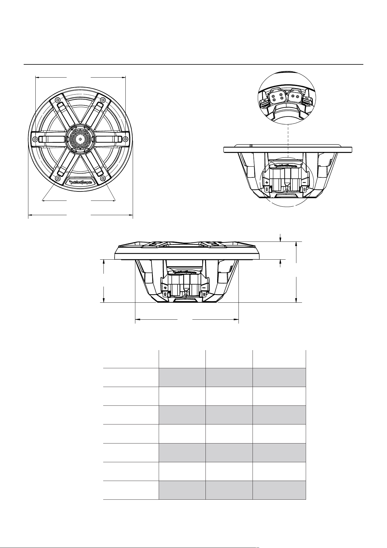
4
Model M1-6
M1-6B
M1-65
M1-65B
M1-8
M1-8B
Overall Diameter
(A)
7.09”
(108.1mm)
7.09”
(108.1mm)
8.23”
(209.1MM)
Screw Mounting
Diameter (B)
6.12”
(155.5mm)
6.12”
(155.5mm)
7.76”
(197.1mm)
Mounting Screw
Angle (C)
6@60° 6@60° 6@60°
Overall Height
(D)
3.54”
(90mm)
3.54”
(90mm)
4.63”
(117.6mm)
Mounting Depth
(E)
2.52”
(63.9mm)
2.52”
(63.9mm)
3.3”
(83.9mm)
Cut-out Diameter
(F)
5.07”
(128.7mm)
5.36”
(136.15mm)
7.1”
(180.2mm)
Grill Height
(G)
1.06”
(26.1mm)
1.06”
(26.1mm)
1.33”
(33.7mm)
DiagramsDiagrams
illus.-1.1
D
E
F
G
B
C
A
illus.-2.1
5
WiringWiring
COLOR OPTIX™ Wiring Precautions
• Do not connect to 24 Volt electrical systems
• We recommend only using the COLOR OPTIX™ wiring chart
or connecting to the PMX-RGB. Connecting any other way
could cause damge to the speakers or the device you have
connected to.
• We recommend installing a fuse (not included) on the
Yellow 12 Volt wire whenever you are NOT using the PMX-
RGB. See COLOR OPTIX™ wiring chart for wiring options.
• Rockford recommends a minimum of 20 gauge wire when
hardwiring your COLOR OPTIX™ speakers.
• Never wire the COLOR OPTIX™ lights directly to 12 volts.
Utilize either the PMX-RGB or a toggle switch (not included)
connected to a fused 12 volt power supply. Refer to the
specifications to determine the size of fuse (not included)
needed
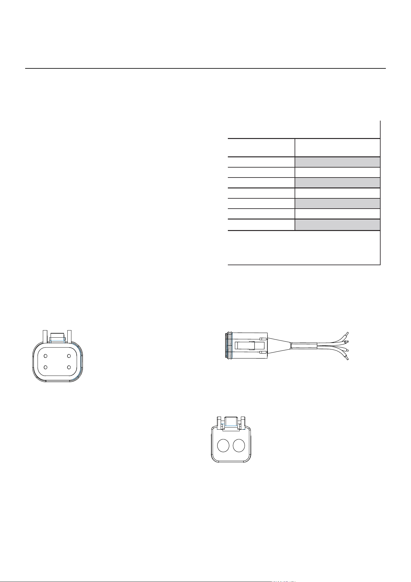
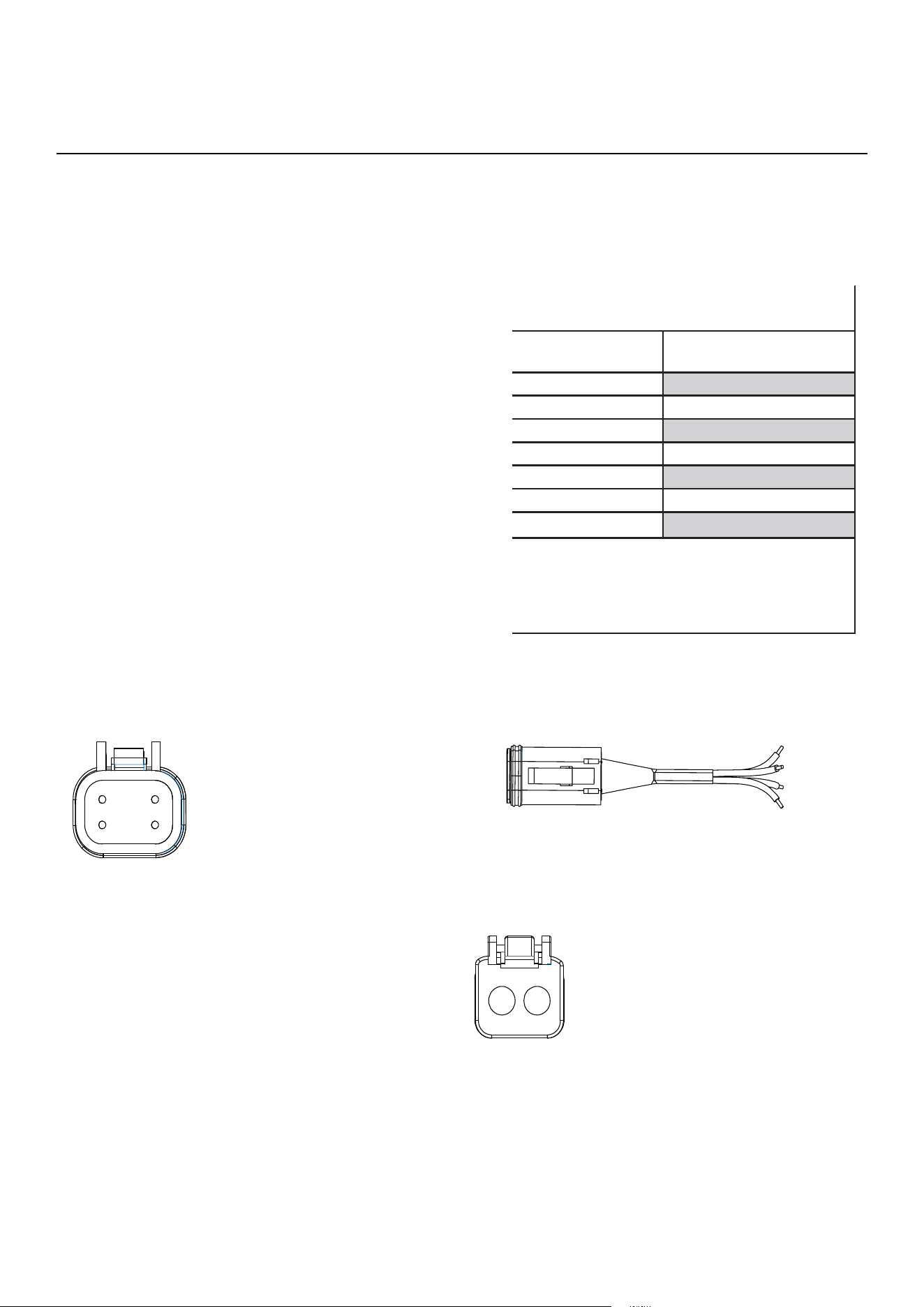
COLOR OPTIX™ WIRING OPTIONS
LED OUTPUT COLOR CONNECT THIS COLOR WIRE
TO GROUND
RED RED
GREEN GREEN
BLUE BLUE
YELLOW RED & GREEN
PINK RED & BLUE
AQUA GREEN & BLUE
WHITE RED, GREEN & BLUE
Connect colored wires on right to make output color
on le.
Connect all Yellow wires together to switched 12
Volts. See Wiring Precautions.
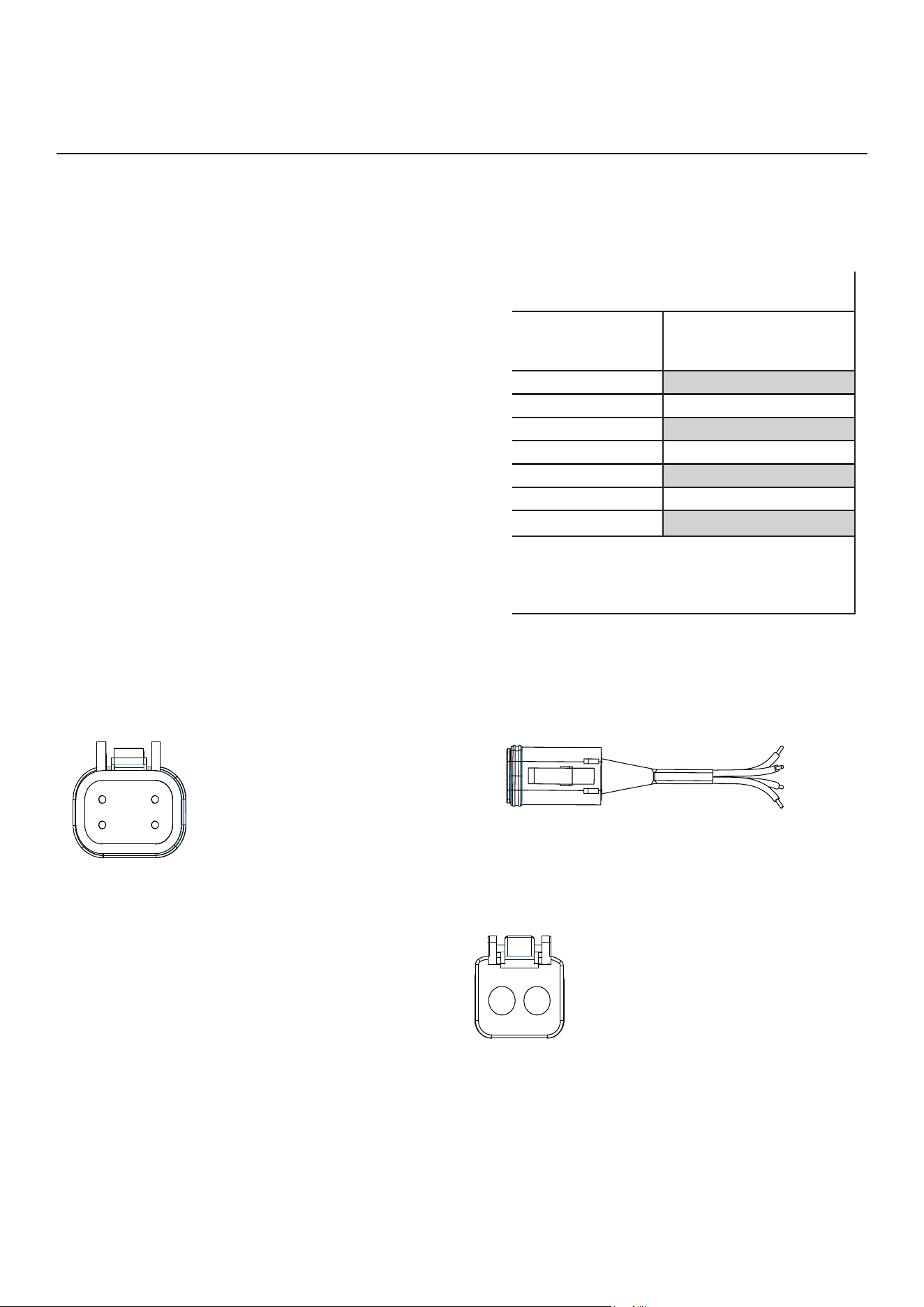
COLOR OPTIX™ Wiring
1 - RED
2 - Yellow
3 - Blue
4 - Green
Included with speakers
Connector is DEUTSC™ style DT06-4S
illus.-4.1
1 2
3 4
Speaker Pin Out (wire side)
1 - RED - Positive Speaker Input
2 - BLACK - Negative Speaker Input
NOT included with speakers
Connector is DEUTSCH™ style DT06-2S
illus.-4.3
1 2
illus.-4.2
Included
SPEAKER Wiring
COLOR OPTIX™ Pin Out (wire side)
COLOR OPTIX™ Connector
If not using the PMX-RGB, follow the diagrams below for proper
pin out and hardwiring instructions.
There are (2) dierent options for wiring your speakers.
Use the included spade connectors (included) as seen in illustra-
tion 3.1
You can also utilize the DEUTSCH™/Ampaenol connector (not
included) input next to the COLOR OPTIX™ connector.

6
Contents
• (1) Pair Marine Grade Speakers
• (13) Socket head stainless screws
• (2) Allen/Hex key drill bit adaptor
• (1) 1/8” Drill Bit
• (2) COLOR OPTIX™ Harness
Installation Considerations
Before beginning any installation, follow these simple rules:
1. Be sure to carefully read and understand the instructions
before attempting to install these speakers.
2. For easier assembly, we suggest you run all wires prior to
mounting your speakers in place.
3. Use high quality connectors for a reliable installation and
to minimize signal or power loss.
4. Think before you drill! Be careful not to cut or drill into gas
tanks, fuel lines, brake or hydraulic lines, vacuum lines or
electrical wiring when working on any vehicle. If installation
in a boat, take care not to cut or drill through the main hull.
5. Never run wires underneath the vehicle. Running the wires
inside the vehicle or hull area provides the best protection.
6. Avoid running wires over or through sharp edges. Use
rubber or plastic grommets to protect any wires routed
through metal, especially the firewall.
Mounting
1. Determine where the speakers will be mounted. Ensure an
area large enough for the speaker to mount evenly. Be sure
that the mounting location is deep enough for the speaker
to fit; if mounting in a door, operate all functions (windows,
locks, etc.) through their entire operating range to ensure
there is no obstruction.
2. Refer to the specification chart to determine the proper
diameter hole to cut for your speaker model. Cutting and
mounting templates can be found at www.rockfordfosgate.
com.
3. Mark the locations for the mounting screws. Drill the holes
with the included 1/8” bit.
4. Feed the speaker wires through the cutout and connect to
the speaker terminals. Be sure to observe proper polarity
when connecting the wires. The speaker’s positive terminal
is indicated with a “+”.
5. Fit the trim ring over the speaker and mount into place
using the four (4) screws that are provided.
6. Tighten the screws until the speaker is snug in place to
prevent rattling. Do not over tighten the screws.
Installation

7
Modèle M1-6
M1-6B
M1-65
M1-65B
M1-8
M1-8B
Diamètre total
(A)
108,1 mm (7,09") 108,1 mm (7,09") 209,1 mm (8,23’)
Montage de vis
Diamètre (B)
155,5 mm (6,12") 155,5 mm (6,12") 197,1 mm (7,76")
Angle de la vis de
montage (C)
6@60° 6@60° 6@60°
Hauteur totale
(D)
90 mm (3,54") 90 mm (3,54") 117,6 mm (4,63")
Profondeur de
montage (E)
63,9 mm (2,52") 63,9 mm (2,52") 83,9 mm (3,3")
Diamètre de
découpe (F)
128,7 mm (5,07") 136,15 mm (5,36") 180,2 mm (7,1")
Hauteur de grille
(G)
26,1 mm (1,06") 26,1 mm (1,06") 33,7 mm (1,33")
SchémasSchémas
illus.-1.1
D
E
F
G
B
C
A
illus.-2.1

8
Câblage
Câblage COLOR OPTIX™ - Précautions
• Ne pas connecter à des systèmes électriques de 24 volts
• Nous recommandons de n'utiliser que le diagramme de
câblage COLOR OPTIX™ ou de se connecter au PMX-RGB. Se
connecter de toute autre façon pourrait endommager les
haut-parleurs ou l'appareil auquel on s'est connecté.
• Nous recommandons d'installer un fusible (non fourni)
sur le fil jaune de 12 volts quand on N'utilise PAS le PMX-
RGB. Voir le diagramme de câblage COLOR OPTIX™ pour les
options de câblage.
• Rockford recommande un fil d'un calibre minimum de 20
lors du raccordement électrique des haut-parleurs COLOR
OPTIX™.
• Ne jamais câbler les lumières COLOR OPTIX™ directement
à du 12 volts. Utiliser soit le PMX-RGB soit un commutateur
à bascule (non fourni) connecté à une alimentation de
12 volts fusionnés. Se référer aux spécifications pour
déterminer la taille du fusible (non fourni) nécessaire
OPTIONS DE CÂBLAGE COLOR OPTIX™
COULEUR DE DEL DE
SORTIE
CONNECTER CE FIL DE COU-
LEUR À LA TERRE
ROUGE ROUGE
VERT VERT
BLEU BLEU
JAUNE ROUGE ET VERT
ROSE ROUGE ET BLEU
AQUA VERT ET BLEU
BLANC ROUGE, VERT ET BLEU
Connecter les fils colorés sur la droite pour créer la
couleur de sortie sur la gauche.
Connecter tous les fils jaunes ensemble à un courant
de 12 volts commutés. Voir les précautions sur le
câblage
Câblage COLOR OPTIX™
1 - ROUGE
2 - Jaune
3 - Bleu
4 - Vert
Fourni avec les haut-parleurs
Le connecteur est DEUTSCH™ style DT06-4S
illus.-4.1
1 2
3 4
Broche de sortie de haut-parleur (côté fils)
1 - ROUGE - Entrée positive de haut-parleur
2 - NOIR - Entrée négative de haut-parleur
NON fourni avec les haut-parleurs
Le connecteur est DEUTSCH™ style DT06-2S
illus.-4.3
1 2
illus.-4.2
Inclus
Câblage de HAUT-PARLEUR
Broche de sortie COLOR OPTIX™ (côté fils)
Connecteur COLOR OPTIX™
Si on n'utilise pas le PMX-RGB, suivre les diagrammes ci-dessous
pour les instructions appropriées de broche de sortie et de
raccordement électrique.
Il y a deux (2) options diérentes pour câbler les haut-parleurs.
Utiliser les connecteurs de rechange fournis comme vu dans
l'illustration 3.1
On peut également utiliser l'entrée du connecteur DEUTSCH™/
Ampaenol (non fourni) à côté du connecteur COLOR OPTIX™.
illus.-2.1

9
Contenu
• (1) Paire de haut-parleurs de qualité marine
• (13) Vis inoxydable à tête creuse
• (2) Mèche à tête creuse
• Mèche 1/8"
• (2) Faisceau COLOR OPTIX™
Considérations d'installation
Avant de commencer toute installation, suivre ces simples
règles :
1. Faire attention de lire attentivement et de comprendre les
instructions avant de tenter d'installer ces haut-parleurs.
2. Pour faciliter l'assemblage, il est conseillé d'acheminer
tous les fils avant de monter les haut-parleurs en place.
3. Utiliser des connecteurs de haute qualité pour une
installation fiable et pour minimiser la perte de signal ou
d'alimentation.
4. Penser avant de percer ! Faire attention de ne pas couper
ni percer dans les réservoirs à essence, les canalisations
de carburant, les conduites de freins ou conduites
hydrauliques, les lignes de vide ou le câblage électrique
lors de toute opération sur un véhicule. En cas d'installation
dans un bateau, faire attention de pas couper ni percer la
coque principale.
5. Ne jamais acheminer les fils sous le véhicule. Acheminer
les fils à l'intérieur du véhicule ou de la surface de la coque
fournit la meilleure protection.
6. Éviter d'acheminer les fils sur ou à travers des bords
coupants. Utiliser des œillets en caoutchouc ou en
plastique pour protéger les fils acheminés dans du métal,
en particulier le pare-feu.
Montage
1. Déterminer où les haut-parleurs seront montés. S'assurer
d'avoir une surface suisamment large pour monter le
haut-parleur uniformément. S'assurer que l'emplacement
de montage est suisamment profond pour que rentre
le haut-parleur ; en cas de montage dans une porte, faire
marcher toutes les fonctions (fenêtres, verrous, etc.) dans
tout leur champ de fonctionnement pour assurer qu'il n'y a
pas d'obstruction.
2. Se référer au diagramme de spécifications pour déterminer
les trous de diamètre appropriés à découper pour le modèle
de haut-parleur. Des gabarits de coupe et de montage se
trouvent à www.rockfordfosgate.com.
3. Marquer les emplacements des vis de montage. Percer les
trous avec la mèche de 1/8” fournie.
4. Acheminer les fils de haut-parleur à travers la découpe et
connecter aux bornes de haut-parleur. S'assurer d'observer
la polarité appropriée lors de la connexion des fils. La borne
positive du haut-parleur est indiquée par un « + ».
5. Fixer la bague de garniture sur le haut-parleur et monter en
place à l'aide des quatre (4) vis fournies.
6. Serrer les vis jusqu'à que le haut-parleur soit bien serré en
place pour éviter tout cliquetis. Ne pas serrer excessivement
les vis.
Installation
10
Diagramas
Modelo M1-6
M1-6B
M1-65
M1-65B
M1-8
M1-8B
Diámetro general
(A)
108.1mm (7.09 pulg.) 108.1mm (7.09 pulg.) 209.1 mm (8.23 pulg.)
Instalación del tornillo
Diámetro (B)
155.5mm (6.12 pulg.) 155.5mm (6.12 pulg.) 197.1mm (7.76 pulg.)
Ángulo de tornillo de
montaje (C)
6@60° 6@60° 6@60°
Altura general
(D)
90mm (3.54 pulg.) 90mm (3.54 pulg.) 117.6mm (4.63 pulg.)
Profundidad de montaje
(E)
63.9mm (2.52 pulg.) 63.9mm (2.52 pulg.) 83.9mm (3.3 pulg.)
Diámetro del recorte
(F)
128.7mm (5.07 pulg.) 136.15mm (5.36 pulg.) 180.2mm (7.1 pulg.)
Altura de la parrilla
(G)
26.1mm (1.06 pulg.) 26.1mm (1.06 pulg.) 33.7mm (1.33 pulg.)
illus.-1.1
D
E
F
G
B
C
A
illus.-2.1

11
Cableado
Precauciones para el cableado de OPTIX COLOR
• No lo conecte a sistemas eléctricos de 24 voltios
• Recomendamos usar solamente la tabla de cableado
COLOR OPTIX™ o conectarse a PMX-RGB. Conectarse de
cualquier otra manera podría dañar los altavoces o el
dispositivo al que se ha conectado.
• Recomendamos instalar un fusible (no incluido) en el cable
amarillo de 12 voltios siempre que NO esté utilizando el
PMX-RGB. Consulte la tabla de cableado de COLOR OPTIX™
para ver las opciones de cableado.
• Rockford recomienda un cable de calibre 20 mínimo al
cablear sus altavoces COLOR OPTIX™.
• Nunca conecte las luces COLOR OPTIX™ directamente a
12 voltios. Utilice el PMX-RGB o un interruptor oscilante
(no incluido) conectado a una fuente de alimentación
con fusible de 12 voltios. Consulte las especificaciones
para determinar el tamaño de fusible (no incluido) que se
necesita
OPCIONES DE CABLEADO COLOR OPTIX™
COLOR DE SALIDA DE
LED
CONECTE ESTE CABLE DE
COLOR A TIERRA
ROJO ROJO
VERDE VERDE
AZUL AZUL
AMARILLO ROJO y VERDE
ROSADO ROJO Y AZUL
AQUA VERDE Y AZUL
BLANCO RED, VERDE Y AZUL
Conecte los cables de colores a la derecha para crear
el color de salida a la izquierda.
Conecte todos los cables amarillos juntos a 12 voltios
conmutados. Consulte las precauciones para el
cableado.
Cableado del COLOR OPTIX™
1 ROJO,
2 - Amarillo
3 - Azul
4 - Verde
Incluido junto con los altavoces
El conector es DEUTSCH™ estilo DT06-4S
ilus.-4.1
1 2
3 4
Disposición de contactos del altavoz
(lado de los cables)
1 - ROJO - Entrada positiva al altavoz
2 - NEGRO - Entrada negativa del altavoz
NO se incluye con los altavoces
El conector es DEUTSCH™ estilo DT06-2S
ilus.-4.3
1 2
ilus.-4.2
Incluye
Cable del ALTAVOZ
Disposición de contactos COLOR OPTIX™
(lado del alambre)
COLOR OPTIX™ Conector
Si no usa el PMX-RGB, siga los diagramas a continuación para
obtener las instrucciones de disposición de contactos y cableado
correctas.
Hay (2) diferentes opciones para cablear sus altavoces.
Utilice los conectores de pala incluidos (incluidos) como se ve en
la ilustración 3.1
También puede utilizar la entrada del conector DEUTSCH™/Am-
paenol (no incluida) junto al conector COLOR OPTIX™.

12
Índice
• (1) Par de altavoces de grado marino
• (13) Tornillos de acero inoxidable de cabeza hueca
• (2) Broca para atornillar tornillos de cabeza hueca
• (1) Broca de taladro de 1/8 pulg.
• (2) Arnés COLOR OPTIX™
Consideraciones para la instalación
Antes de comenzar cualquier instalación, siga estas simples
normas:
1. Asegúrese de leer cuidadosamente y de entender las
instrucciones antes de tratar de instalar estos altavoces.
2. Para facilitar el montaje, sugerimos que tienda todos los
cables antes de montar sus altavoces en su sitio.
3. Utilice conectores de alta calidad para tener una instalación
confiable y para reducir al mínimo las pérdidas de señal o
de potencia.
4. ¡Piense siempre antes de perforar! Tenga cuidado de no
cortar ni perforar tanques de combustible, tuberías de
combustible, de frenos o hidráulicas, tuberías de vacío o
cableado eléctrico al trabajar en cualquier vehículo. Si la
instalación se hace en una embarcación, tenga cuidado de
no cortar ni perforar a través del casco principal.
5. Nunca tienda cables abajo del vehículo. Tender los
cables adentro del vehículo o casco proporciona la mejor
protección.
6. Evite tender cables arriba o a través de bordes filosos. Use
arandelas aislantes de caucho para proteger los cables
tendidos a través de metal, especialmente en la mampara
cortafuegos.
Montaje
1. Determine adónde se montarán los altavoces. Asegúrese
de que haya un área suficientemente grande para montar
de manera plana el altavoz. Asegúrese de que el lugar de
montaje sea suficientemente profundo para que quepa
el altavoz, si se monta en una puerta, accione todas las
funciones (ventanas, cerradura, etc.) en toda su gama
de funcionamiento para asegurarse de que no haya
obstrucciones.
2. Consulte la tabla de especificaciones para determinar
cuales son los diámetros correctos para el agujero a cortar
para su modelo de altavoz. Se puede encontrar las plantillas
para el corte y el montaje en www.rockfordfosgate.com.
3. Marque las localidades para los tornillos de montaje.
Perfore los agujeros usando una broca de 1/8 pulg.
4. Tienda los cables del altavoz a través del recorte y conecte
a los terminales del altavoz. Asegúrese de usar la polaridad
correcta al conectar los cables. El terminal positivo del
altavoz está identificado con un símbolo "+".
5. Coloque el anillo de acabado sobre el altavoz y móntelo en
su sitio usando los cuatro (4) tornillos proporcionados.
6. Apriete los tornillos hasta que el altavoz esté ajustado en
su sitio para evitar vibraciones. No apriete demasiado los
tornillos.
Instalación
13
Modell M1-6
M1-6B
M1-65
M1-65B
M1-8
M1-8B
Gesamtdurchmesser
(A)
108,1 mm 108,1 mm 209,1 mm
Schraubbefestigung
Durchmesser (B)
155,5 mm 155,5 mm 197,1 mm
Montageschraubenwin-
kel (C)
6@60° 6@60° 6@60°
Gesamthöhe
(D)
90 mm 90 mm 117,6 mm
Einbautiefe
(E)
63,9 mm 63,9 mm 83,9 mm
Ausschnittdurchmesser
(F)
128,7 mm 136,15 mm 180,2 mm
Gitterhöhe
(G)
26,1 mm 26,1 mm 33,7 mm
Diagramme
illus.-1.1
D
E
F
G
B
C
A
illus.-2.1
14
Vorsichtsmaßnahmen für die COLOR OPTIX™
Verkabelung
• Nicht an 24-Volt-Spannung anschließen
• Wir empfehlen nur die Verwendung der COLOR OPTIX™
Verkabelungstabelle oder den Anschluss an PMX-RGB
Andere Arten von Anschlüssen können die Lautsprecher
oder das angeschlossene Gerät beschädigen.
• Wir empfehlen, eine Sicherung (nicht im Lieferumfang)
am gelben 12-Volt-Kabel zu installieren, wenn Sie das
PMX-RGB NICHT verwenden. Siehe COLOR OPTIX™
Verkabelungstabelle für Verkabelungsoptionen.
• Rockford empfiehlt eine Kabelstärke von mindestens
20 Gauge für die Festverdrahtung Ihrer COLOR OPTIX™
Lautsprecher.
• COLOR OPTIX™ Lichter nie direkt an 12 Volt anschließen.
Verwenden Sie entweder PMX-RGB oder einen Kippschalter
(nicht im Lieferumfang), der an ein gesichertes 12-Volt-
Netzteil angeschlossen ist. Weitere Informationen zur
erforderlichen Sicherungsgröße (nicht im Lieferumfang)
finden Sie in den technischen Daten.
VERKABELUNGSOPTIONEN FÜR COLOR
OPTIX™
LED-AUSGANGSFARBE DIESES FARBIGE KABEL AN
DIE ERDUNG ANSCHLIESSEN
ROT ROT
GRÜN GRÜN
BLAU BLAU
GELB ROT U. GRÜN
PINK ROT U. BLAU
AQUA GRÜN U. BLAU
WEISS ROT, GRÜN U. BLAU
Schließen Sie die farbigen Kabel rechts für die
Ausgangsfarbe links an.
Schließen Sie alle gelben Kabel zusammen an einem
12-Volt-Schaltkreis an. Siehe Vorsichtsmaßnahmen
für die Verkabelung.
COLOR OPTIX™ Verkabelung
1 - ROT
2 - Gelb
3 - Blau
4 - Grün
Mit den Lautsprechern
mitgeliefert
Konnektor ist DEUTSCH™ Stil DT06-4S
Abb. - 2.1
1 2
3 4
Lautsprecher-Stikontakte (Drahtseite)
1 - ROT - Positiver Lautsprechereingang
2 - SCHWARZ - Negativer
Lautsprechereingang
NICHT im Lieferumfang mit den
Lautsprechern
Konnektor ist DEUTSCH™ Stil DT06-2S
Abb. - 4.3
1 2
Abb. - 1.1
Mitgeliefert
LAUTSPRECHER-Verkabelung
COLOR OPTIX™ Stikontakte (Drahtseite)
COLOR OPTIX™ Konnektor
Wenn Sie PMX-RGB nicht verwenden, folgen Sie den Diagrammen
unten für die Anleitungen für die korrekten Stikontakte und
Festverdrahtung.
Es gibt (2) verschiedene Optionen für die Verkabelung Ihrer
Lautsprecher.
Verwenden Sie die mitgelieferte Flachsteckhülse wie in
Abbildung 3.1. Sie können auch den DEUTSCH™-Konnektor-
Eingang (DEUTSCH™/Ampaenol-Konnektor nicht im
Lieferumfang) neben dem COLOR OPTIX™ Konnektor verwenden.
Verkabelung

15
Inhalt
• (1) Paar wasserbeständige Lautsprecher
• (13) Edelstahl-Sechskantschrauben
• (2) Sechskant-Schraubendreher
• (1) 1/8-Zoll-Bohrerspitze
• (2) COLOR OPTIX™ Kabelband
Informationen zum Einbau
Vor dem Einbau diese einfachen Regeln befolgen:
1. Vor dem Einbau dieser Lautsprecher die Anleitungen
sorgfältig durchlesen und verstehen.
2. Um die Montage zu erleichtern, empfehlen wir, alle Kabel
vor der Befestigung Ihrer Lautsprecher zu verlegen.
3. Nur Qualitätsstecker verwenden, um einen zuverlässigen
Einbau zu gewährleisten und Signal- und Stromverlust zu
minimieren.
4. Vorsicht vor dem Bohren! Bei Arbeiten am Fahrzeug
darauf achten, nicht in den Benzintank, in die Benzin-,
Brems- oder hydraulischen Leitungen, Vakuumleitungen
oder Elektrokabel zu schneiden oder zu bohren. Bei der
Installation auf einem Boot sicherstellen, dass nicht durch
den Rumpf gebohrt oder geschnitten wird.
5. Kabel nie unter dem Fahrzeug verlegen. Verlegen der Kabel
im Fahrzeug oder im Rumpf bietet den besten Schutz.
6. Verlegen der Kabel über oder durch scharfe Kanten
vermeiden. Gummi- oder Plastik-Dichtungshülsen
verwenden, um Kabel zu schützen, die durch Metall verlegt
werden, insbesondere durch die Feuerwand.
Einbau
1. Legen Sie fest, wo die Lautsprecher eingebaut werden sollen.
Stellen Sie sicher, dass genügend Platz für die Lautsprecher
vorhanden ist, damit diese gleichmäßig installiert werden.
Stellen Sie sicher, dass die Befestigungsstelle für die
Lautsprecher tief genug ist; bei Befestigung an einer Tür
alle Funktionen (Fenster, Schlösser, usw.) für den gesamten
Bewegungsablauf prüfen, um sicherzustellen, dass es keine
Behinderung gibt.
2. Weitere Informationen zum korrekten Durchmesser des
Lochs für Ihr Lautsprechermodell finden Sie in der Tabelle mit
den technischen Daten. Schneide- und Einbauschablonen
finden Sie unter www.rockfordfosgate.com.
3. Markieren Sie die Stellen für die Befestigungsschrauben.
Bohren Sie die Löcher mit der mitgelieferten 1/8-Zoll-
Bohrspitze.
4. Führen Sie die Lautsprecherkabel durch den Ausschnitt
und schließen Sie diese an die Lautsprecheranschlüsse
an. Beachten Sie die richtige Polarität beim Anschließen
der Kabel. Der positive Anschluss des Lautsprechers ist mit
einem „+“ gekennzeichnet.
5. Ziehen Sie den Klemmflansch über den Lautsprecher und
befestigen Sie diesen mit Hilfe der vier (4) mitgelieferten
Schrauben.
6. Ziehen Sie die Schrauben fest, bis der Lautsprecher sicher
befestigt ist und nicht klappert. Die Schrauben nicht
überdrehen.
Einbau

16
Modello M1-6
M1-6B
M1-65
M1-65B
M1-8
M1-8B
Diametro totale
(A)
108,1 mm 108,1 mm 209,1 mm
Montaggio viti
diametro (B)
155,5 mm 155,5 mm 197,1 mm
Angolo della vite
di montaggio (C)
6@60° 6@60° 6@60°
Altezza totale
(D)
90 mm 90 mm 117,6 mm
Profondità di
montaggio (E)
63,9 mm 63,9 mm 83,9 mm
Diametro del foro
ritagliato (F)
128,7 mm 136,15 mm 180,2 mm
Altezza della
griglia (G)
26,1 mm 26,1 mm 33,7 mm
Diagrammi
illus.-1.1
D
E
F
G
B
C
A
illus.-2.1
17
Precauzioni Cablaggio COLOR OPTIX™
• Non collegare a sistemi elettrici a 24 Volt
• Consigliamo di usare solo la tabella di cablaggio COLOR
OPTIX™ o di collegare PMX-RGB. Qualsiasi altro tipo di
collegamento potrà danneggiare gli altoparlanti o il
dispositivo che avete collegato.
• Consigliamo di installare un fusibile (non incluso) sul
cavo giallo da 12 Volt quando NON si usa il PMX-RGB. Vedi
la tabella di cablaggio COLOR OPTIX™ per le opzioni di
cablaggio.
• Rockford consiglia un filo di minimo 20 gauge per il
cablaggio degli altoparlanti COLOR OPTIX™.
• Mai cablare le luci COLOR OPTIX™ direttamente in 12 Volt.
Usare PMX-RGB o un interruttore (non incluso) collegato
a un’alimentazione munita di fusibile a 12 Volt. Fare
riferimento ai dati tecnici per determinare le dimensioni
del fusibile.
OPZIONI DI CABLAGGIO COLOR OPTIX™
COLORE USCITA LED COLLEGARE QUESTO FILO
COLORATO ALLA MESSA A
TERRA
ROSSO ROSSO
VERDE VERDE
BLU BLU
GIALLO ROSSO E VERDE
ROSA ROSSO E BLU
COLORE ACQUA VERDE E BLU
BIANCO ROSSO, VERDE E BLU
Collegare i fili colorati sulla destra per produrre il
colore di uscita sulla sinistra.
Collegare tutti i fili gialli insieme alla fonte commuta-
ta a 12 Volt. Vedi Precauzioni cablaggio.
Cablaggio COLOR OPTIX™
1- ROSSO
2- Giallo
3 - Blu
4 - Verde
Incluso con gli altoparlanti
Il connettore è DEUTSCH™ stile DT06-4S
illus.-4.1
1 2
3 4
Pin-out Altoparlante (lato fili)
1 - ROSSO - Ingresso positivo
altoparlante
2 - NERO - Ingresso negativo
altoparlante
NON incluso con gli altoparlanti
Il connettore è DEUTSCH™ stile DT06-2S
illus.-4.3
1 2
illus.-4.2
incluso
Cablaggio ALTOPARLANTI
Pin-out COLOR OPTIX™ (lato fili)
Connettore COLOR OPTIX™
Se non si usa PMX-RGB, seguire i diagrammi sotto per i giusti pin-
out e le istruzioni di cablaggio.
Esistono (2) opzioni diverse per il cablaggio degli altoparlanti.
Usare i connettori a forcella (inclusi) come da illustrazione 3.1.
E’ anche possibile usare l’ingresso del connettore DEUTSCH™/
Ampaenol (non incluso) vicino al connettore COLOR OPTIX™:
Cablaggio

18
Contenuto
• (1) paio di altoparlanti marini
• (13) viti a testa esagonale inox
• (2) punte esagonali
• (1) punta di trapano da 1/8 pollice
• (2) cablaggi COLOR OPTIX™
Considerazioni sull'installazione
Prima di procedere con l'installazione seguire queste semplici
regole:
1. Leggere attentamente le istruzioni e comprenderle prima di
iniziare l'installazione di questi altoparlanti.
2. Per facilitare l'assemblaggio consigliamo di passare tutti
i cavi nella posizione d'installazione prima di montare gli
altoparlanti.
3. Usare connettori di alta qualità per un'installazione
aidabile e per minimizzare la perdita di segnale o potenza.
4. Attenzione prima di trapanare! Attenzione a non tagliare
o trapanare il serbatoio della benzina, le tubazioni del
carburante, le linee freno o idrauliche, le linee da vuoto
o i cavi elettrici quando si lavora su qualsiasi veicolo. Per
installazioni in barca fare attenzione a non tagliare o
trapanare lo scafo.
5. Mai passare i cavi sotto il veicolo. Si ottiene la protezione
migliore facendo scorrere i cavi all’interno del veicolo o
dello scafo.
6. Evitare di passare i cavi sopra o attraverso bordi taglienti.
Usare guarnizioni in gomma o plastica per proteggere i cavi
che si fanno passare attraverso il metallo, soprattutto la
parete parafiamma.
Montaggio
1. Determinare la posizione di montaggio degli altoparlanti.
Assicurarsi che l’area sia grande abbastanza per potere
montare gli altoparlanti in modo uniforme. Assicurarsi che
la posizione di montaggio sia suicientemente profonda
per gli altoparlanti; per il montaggio su porta provare
l’intero movimento di tutte le funzioni (finestre, serrature,
ecc.) per garantire che non vi sia nessuna ostruzione.
2. Fare riferimento alla tabella con i dati tecnici per
determinare il giusto diametro del foro da ritagliare per
il vostro modello di altoparlante. Sagome di taglio e
montaggio si trovano su www.rockfordfosgate.com.
3. Segnare i punti per le viti di montaggio. Trapanare i fori con
la punta da 1/8 pollici inclusa.
4. Far passare i fili dell’altoparlante attraverso il foro e
collegare ai terminali dell’altoparlante. Accertarsi che
combacino le polarità quando si collegano i fili. Il terminale
positivo dell’altoparlante è contrassegnato con “+”.
5. Mettere l’anello di rivestimento sull’altoparlante e fissarlo
usando le quattro (4) viti incluse.
6. Stringere le viti finché l’altoparlante è fisso in posizione per
prevenire spostamenti. Non stringere eccessivamente le
viti.
Installazione

19
NOTE

20
Rockford Corporation oers a limited warranty on Rockford Fosgate products on the following terms:
Length of Warranty
POWER Amplifiers – 2 Years
BMW® Direct Fit Speakers – 2 Years
PUNCH® & PRIME® Amplifiers – 1 Year
Speakers, Signal Processors, Accessories and Capacitors – 1 Year
All marine, motorcycle, motorsport products - 2 Years
Any Factory Refurbished Product – 90 Days (receipt required)
What is Covered
This warranty applies only to Rockford Fosgate products sold to consumers by authorized Rockford Fosgate dealers in the United
States of America. Products purchased by consumers from an Authorized Rockford Fosgate Dealer in another country are covered
only by that country’s Distributor and not by Rockford Corporation.
Who is Covered
This warranty covers only the original purchaser of Rockford product purchased from an authorized Rockford Fosgate dealer in the
United States. In order to receive service, the purchaser must provide Rockford with a copy of the receipt stating the customer name,
dealer name, product purchased and date of purchase.
Products found to be defective during the warranty period will be repaired or replaced (with a product deemed to be equivalent) at
Rockford’s discretion.
What is Not Covered
1. Damage caused by accident, abuse, improper installation, operations, the, water (on non-Element Ready products).
2. Any cost or expense related to the removal or reinstallation of product.
3. Service performed by anyone other than Rockford or an authorized Rockford Fosgate service center.
4. Any product which has had the serial number defaced, altered, or removed.
5. Subsequent damage to other components.
6. Any product purchased outside the U.S.
7. Any product not purchased from an authorized Rockford Fosgate dealer. Refer to rockfordfosgate.com dealer locator for more
detail.
Limit on Implied Warranties
Any implied warranties including warranties of fitness for use and merchantability are limited in duration to the period of the express
warranty set forth above. Some states do not allow limitations on the length of an implied warranty, so this limitation may not apply.
No person is authorized to assume for Rockford Fosgate any other liability in connection with the sale of the product.
How to Obtain Service
Please call 1-800-669-9899 for Rockford Customer Service. You must obtain an RA# (Return Authorization number) to return any prod-
uct to Rockford Fosgate. You are responsible for shipment of product to Rockford.
EU Warranty
This product meets the current EU warranty requirements, see your Authorized dealer for details.
Warranty

600 South Rockford Drive • Tempe, Arizona 85281 United States
Direct: (480) 967-3565 • Toll Free: (800) 669-9899
rockfordfosgate.com
120419 1230-73021-01-B Printed In China
Inst
allation assis
ta
nc
e av
ailable at
: