Loading ...
Loading ...
Loading ...
Optional Supply Air Sensor Wiring
3.3
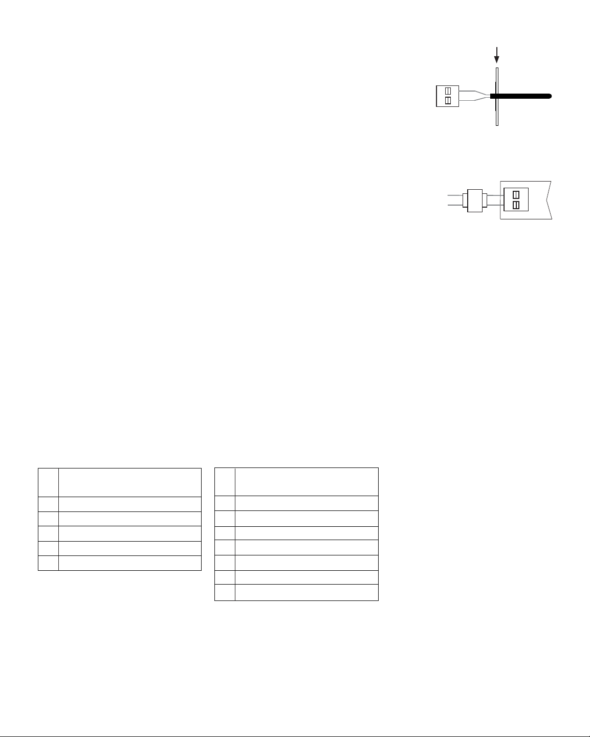
To provide high/low limit protection, install the optional supply air sensor in the
supply air plenum at least 2-3 feet after the heat exchanger and coil. Make sure
there are no zone dampers before the supply air sensor. Connect the supply air
sensor to the zone panel as shown.
SA1
SA2
Transformer Wiring
3.4
Install the transformer using the instructions provided by the manufacturer. Size the
transformer to the damper requirements. The zone panel has built-in, self-resetting
fuses. The maximum damper power per panel is 100 VA at 24 VAC. Connect the
transformer to the zone panel as shown.
NOTE: Additional dampers or dampers with a higher current draw will require the
use of a separate slave relay.
ALWAYS PROVIDE DISCONNECT AND OVERLOAD PROTECTION AS REQUIRED
24V
24C
CC
HOT
Dedicated
Zoning Transformer
Zone
Panel
Conventional Equipment Wiring
3.5
NOTE: For a heat pump system, see Section 3.6.
Connect a conventional heating system to the zone panel as shown. For a single stage heating and cooling
system, the 2nd and 3rd stage connections are not used. For a system using a dual transformer, remove
jumper Rc to Rh (see Figure 3, page 4). Make sure the neutrals (common) are connected.
ALWAYS PROVIDE DISCONNECT AND OVERLOAD PROTECTION AS REQUIRED
8
1 HEAT / 1 COOL Equipment
Set Equipment Type to SSC
Rh
24 VAC Power (Heating Transformer)
[Note 3]
Rc Cooling Transformer [Note 3]
W1 Heat Call
Y1 Cooling Call
G Fan Call
C 24 VAC Transformer Common
2 HEAT / 2 COOL Equipment
Set Equipment Type to MSC
Rh
24 VAC Power (Heating Transformer)
[Note 3]
Rc Cooling Transformer [Note 3]
W1 Heat Call Stage 1
W2 Heat Call Stage 2
Y1 Cooling Call Stage 1
Y2 Cooling Call Stage 2
G Fan Call
C 24 VAC Transformer Common
NOTES
[3] Remove J1 jumper for dual transformer systems. Transformer common must come from cooling transformer.
Plenum
Loading ...
Loading ...
Loading ...