INSTALLATION
1.
Pour éviter les risques d’incendie et d’électrocution, couper
le courant en ouvrant le disjoncteur ou en retirant le fusible.
Vérifier que le circuit est hors tension avant de commencer
l’installation.
2. INSTALLER LA BOÎTE DE JONCTION
Installer une boîte de jonction simple de 2 ½ po de
profondeur ou une boîte de jonction double de 2 po de
profondeur.
3. BRANCHER LES FILS
Instructions générales pour toute installation :
Veiller à ce que la boîte de jonction et l’interrupteur soient
correctement mis à la terre.
Vérifier que le fil de mise à la terre est bien fixé à la vis de
mise à la terre de l’interrupteur. Serrer la vis de mise à la terre
à un couple de 1,6 à 1,8N·m (14 à 16 po/lb).
Retirer environ 1,6 cm (5/8 po) de gaine des fils. Utiliser des
capuchons de connexion de la taille appropriée au nombre
de fils et à leur calibre.
Pour les connexions aux bornes à vis, utiliser uniquement
des fils rigides (monobrin) en cuivre de calibre 12 ou
14AWG. Serrer les bornes à vis à un couple de 1,6 à 1,8N·m
(14 à 16 po/lb).
Pour l’interrupteur à trois fonctions, dégainer l’extrémité des
fils en utilisant le guide de longueur au dos de l’interrupteur.
Brancher les fils comme l’indique le schéma de câblage à la
figure3.
MODÈLE P2RW INTERRUPTEUR À BASCULE À DEUX FONCTIONS
MODÈLE P3RW INTERRUPTEUR À BASCULE À TROIS FONCTIONS
Commande de deux ou trois appareils séparément.
CONSIGNES DE SÉCURITÉ
TOUS LES TRAVAUX ÉLECTRIQUES DOIVENT ÊTRE FAITS
CONFORMÉMENT AUX CODES ET RÈGLEMENTS LOCAUX
APPLICABLES. POUR DES RAISONS DE SÉCURITÉ, LE
PRODUIT DOIT ÊTRE INSTALLÉ DANS UNE BOÎTE DE
JONCTION MISE À LA TERRE. EN CAS DE DOUTE QUANT AU
BRANCHEMENT DES FILS, RECOURIR AUX SERVICES D’UN
ÉLECTRICIEN.
Avant de commencer l’installation ou le branchement du produit,
couper le courant et vérifier que le circuit est hors tension.
Utiliser l’interrupteur à bascule uniquement avec des fils en cuivre
ou revêtus de cuivre. Ne pas utiliser avec des fils en aluminium.
Pour éviter les dommages aux composants électriques et
les blessures graves causées par l’électrocution, NE PAS
BRANCHER DES FILS SOUS TENSION. Couper le courant en
ouvrant le disjoncteur du circuit où sera installé l’interrupteur.
L’interrupteur à bascule peut recevoir une charge totale nominale
de 15 A à 120VCA.
Ne pas dépasser cette charge.
Garantie nulle en cas de mauvais branchement.
Pour l’interrupteur à deux fonctions, brancher les fils
comme l’indique le schéma de câblage à la figure1 (pour
deux interrupteurs unipolaires sur un même circuit) ou celui
à la figure2 (pour deux interrupteurs unipolaires sur deux
circuits). Peu importe la méthode, les deux interrupteurs
unipolaires commandent chacun une fonction.
N.B. : Avant de brancher les fils dans une installation à deux
circuits (figure2), retirer la languette d’interruption entre les
deux vis noires de l’interrupteur avec un tournevis à pointe
plate. Bouger le tournevis de haut en bas jusqu’à ce que la
languette se détache.
4. FIXER L’INTERRUPTEUR À BASCULE DANS LA BOÎTE DE
JONCTION
Pousser les fils dans la boîte de jonction et y fixer
l’interrupteur avec les vis fournies.
5. INSTALLER LA PLAQUE MURALE
Fixer une plaque murale (non comprise) sur l’interrupteur à
bascule.
MODEL P2RW 2-ROCKER SWITCH
MODEL P3RW 3-ROCKER SWITCH
Control 2 or 3 devices independently
SAFETY WARNINGS
ALL ELECTRICAL WORK MUST BE DONE IN
ACCORDANCE WITH LOACL CODES, ORDINANCES,
OR NATIONAL ELECTRICAL CODE AS APPLICABLE.
FOR SAFETY, THIS PRODCUT MUST BE INSTALLED IN
A GROUNDED SWITCH BOX. IF YOU ARE UNFAMILIAR
WITH METHODS OF INSTALLING ELECTRICAL
WIRING, SECURE THE SERVICES OF A QUALIFIED
ELECTRICIAN.
Turn off power before installing or wiring this product
and test that the power is off.
Use this rocker switch only with copper or copper-clad
wire. Do not use aluminum wire with this device.
To prevent serious injury from electrical shock or
damage to electrical components – DO NOT WIRE HOT!
Turn off power breaker to this switch.
Total load for the multi-rocker switch is rated at 15
amps, @ 120 VAC.
Do not exceed maximum electrical ratings.
Warranty is void if miswired.
INSTALLATION STEPS
1.
To avoid fire or electrical shock, turn OFF power at
circuit breaker or fuse. Test that the power is OFF
before working.
2. MOUNT THE SWITCH BOX
Install a 2 1/2 inch deep single-gang switch box or a
2 inch deep double-gang switch box.
3. CONNECT WIRING
General instructions for all configurations:
Make sure both the switch box and the appliance are
properly grounded.
Make sure ground wire is securely fastened to rocker
switch’s ground screw. Tighten ground screw 14 to
16-in. lbs. torque.
Remove insulation, approx. 5/8 inch. Use proper
wire nut sizes for number and size of wires.
For screw terminals: Use #12 or #14-AWG solid
copper wire only. Tighten screw terminals 14 to 16
inch lbs. torque.
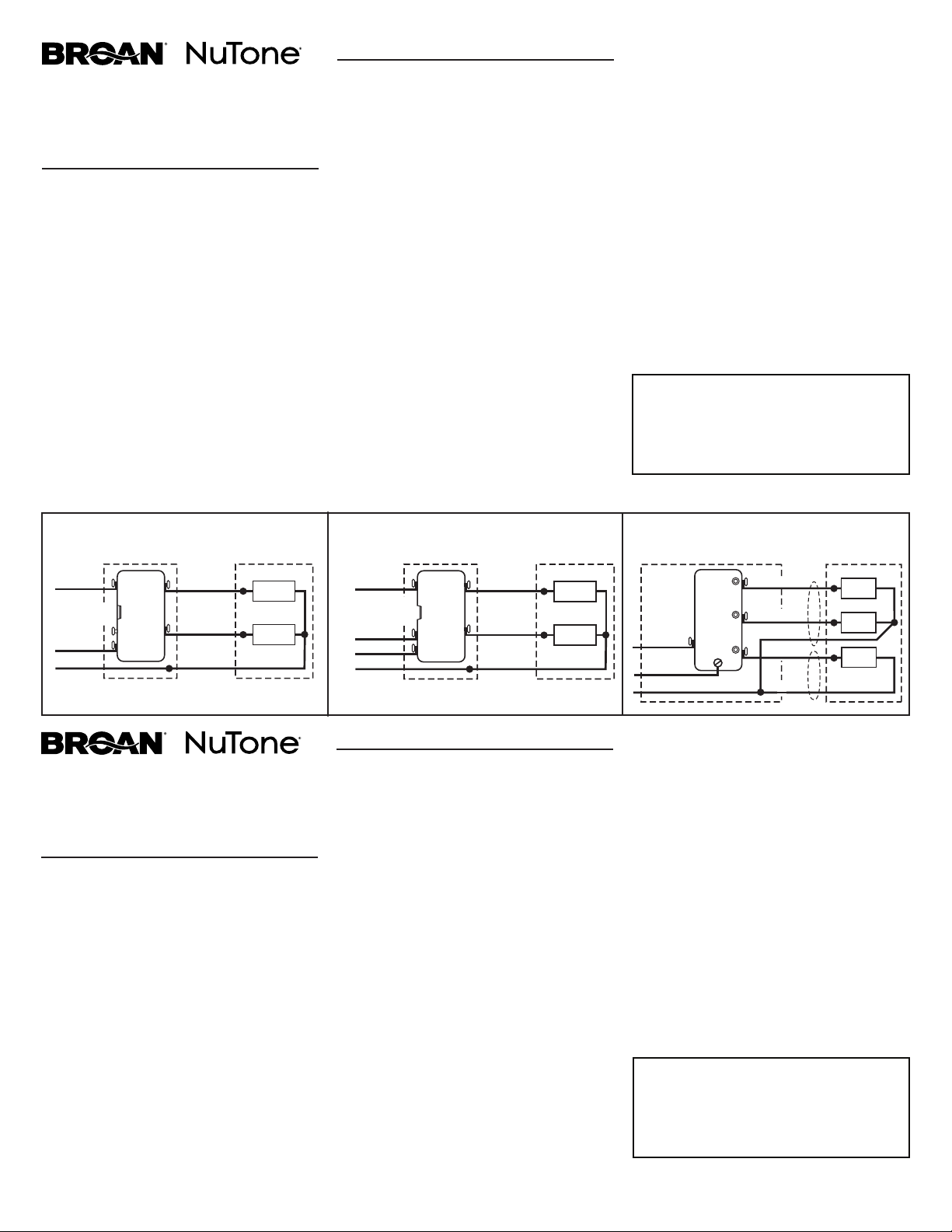
For 3-rocker units: Strip wires to length of strip
gauge on the back of the switch. Connect wires per
the FIGURE #3 wiring diagram.
For 2-rocker units: Connect wires per either the
FIGURE #1 wiring diagram (two single pole switches
on the same circuit) or the FIGURE #2 wiring diagram
(two single pole switches on separate circuits). With
either method, each single pole switch controls an
independent function.
NOTE: For separate feed (FIGURE #2) operation
only: The break-off tab located between the black
screws should be removed before wiring. Using a
standard slotted screwdriver, move the screwdriver
up and down in the vertical direction until the tab
breaks off.
4. MOUNT ROCKER SWITCH IN SWITCH BOX
Tuck wires into switch box and fasten the rocker
switch to box using attached screws.
5. ATTACH SWITCH PLATE
Fasten a switch plate (not included) to the rocker
switch
BLACK
WHITEWHITE
GROUND
1 20 VAC
LINE IN
BLACK
LOAD
1
LOAD
2
SINGLE-GANG
SWITCH BOX APPLIANCE
RED
BREAK-OFF
T
AB INTACT
2-ROCKER SWITCH 2-ROCKER SWITCH 3-ROCKER SWITCH
BLACK
WHITEWHITE
GROUND
1 20 VAC
LINE 1 IN
LOAD
1
LOAD
2
SINGLE-GANG
SWITCH BOX APPLIANCE
RED
BREAK-OFF
T
AB REMOVED
1 20 VAC
LINE 2 IN
WHITE
DOUBLE-GANG SWITCH BOX
(with single device adapter plate) APPLIANCE
GROUND
BLACK
WHITE
BLACK
LOAD
1
LOAD
2
LOAD
3
RED
WHITE
120 VAC
LINE IN
Figure #1
Figure #2 Figure #3
For Warranty Statement, Service Parts, Technical
Support, or to Register your product, please visit our
website or call:
In the United States - Broan.com 800-637-1453 or
NuTone.com 888-336-6151. In Canada - Broan.ca or
NuTone.ca 877-896-1119
Pour obtenir un relevé de garantie, des pièces de rechange, un
support technique ou pour enregistrer votre produit, veuillez
visiter notre site Web ou appeler:
Aux États-Unis - Broan.com 800-637-1453 ou NuTone.com
888-336-6151
Au Canada - Broan.ca ou NuTone.ca 877-896-1119

MODELO P2RW INTERRUPTOR BASCULANTE BIFUNCIONAL
MODELO P3RW INTERRUPTOR BASCULANTE TRIFUNCIONAL
Para comandar dos o tres dispositivos independientemente.
DIRECTIVOS DE SEGURIDAD
TODA INSTALACIÓN ELÉCTRICA DEBE SER CONFORME A LOS
CÓDIGOS Y REGLAMENTACIONES EN VIGENCIA, INCLUSO EL
CÓDIGO ELÉCTRICO NACIONAL APLICABLE. POR RAZONES
DE SEGURIDAD, ESTE PRODUCTO DEBE SER INSTALADO
EN UNA CAJA DE INTERRUPTOR QUE ESTÉ CONECTADA A
TIERRA. SI NO ESTÁ FAMILIARIZADO CON LOS MÉTODOS
DE INSTALACIÓN DE CABLEADO ELÉCTRICO, POR FAVOR
CONTRATE LOS SERVICIOS DE UN ELECTRICISTA CALIFICADO.
Desconecte la electricidad antes de instalar o cablear el producto.
Conduce una prueba para asegurarse de que todo esté apagado.
El interruptor basculante se debe utilizar solamente con cables de
cobre o cables revestidos de cobre. No utilice cables de aluminio.
Para evitar daños a los componentes eléctricos o lesiones
graves causadas por descargas eléctricas, ¡NO CABLEE EL
INTERRUPTOR CUANDO HAY ELECTRICIDAD! Apague el
disyuntor antes.
El cargo total para el interruptor basculante multifuncional es de
15amperios a 120 VCA.
No exceda la carga máxima.
La garantía quedará anulada en caso de cableado malo.
ETAPAS DE LA INSTALACIÓN
1.
Para evitar incendios o descargas eléctricas, DESCONECTE
el disyuntor o fusible. Conduzca una prueba para asegurarse
de que todo esté APAGADO.
2. MONTE LA CAJA DE INTERRUPTOR
Instale una caja de control único de 2 ½" de profundidad o
una caja de control doble de 2" de profundidad.
3. CONECTE EL CABLEADO
Directivos generales para cualquier configuración:
Verifique que la caja y el dispositivo estén conectados a
tierra.
Verifique que el cable de tierra esté conectado firmemente al
tornillo de tierra del interruptor basculante. Apriete el tornillo
de tierra con un torque de 1,6 a 1,8 N m (14 a 16 lb in).
Retire aproximadamente 1,6 cm (5/8") de aislante del
cableado. Utilice capuchones de tamaño apropiado para la
cantidad y el calibre de los cables.
Para la conexión en los bornes de enlace, utilice un hilo
de cobre de 12 o 14 AWG. Apriete con un torque de 1,6 a
1,8Nm (14 a 16 lb in).
Para una instalación trifuncional, consulte la guía en la parte
trasera del interruptor y retire la longitud idónea del aislante
del cableado. Conecte los cables según el gráfico de la
FIGURA3.
Para una instalación bifuncional, conecte los cables según el
gráfico de la FIGURA1 (para dos interruptores unipolares en
el mismo circuito) o el de la FIGURA2 (para dos interruptores
unipolares en dos circuitos distintos). Con ambos métodos,
cada interruptor unipolar comanda una función distinta.
NOTA: Antes de conectar el cableado en dos circuitos
distintos (FIGURA 2), retire la lengüeta del interruptor,
ubicada entre los tornillos negros. Usando un destornillador
plano estándar, mueva el destornillador verticalmente de
arriba a abajo hasta que la lengüeta se separe.
4. INSTALE EL INTERRUPTOR BASCULANTE EN LA CAJA
Meta los cables dentro de la caja y atornille el interruptor en
la caja.
5. INSTALE LA PLACA
Instale una placa (no incluida) sobre el interruptor.
1101840A
N OIR
BLANCBLANC
MISE À
LA TERRE
A
LIMENTATION
DE 120 V CA
N OIR
CHARGE
1
CHARGE
2
B OÎTE DE JONCTION
SIMPLEI
NTERRUPTEUR
ROUGE
L ANGUETTE
INTACTE
INTERRUPTEUR À DEUX FONCTIONS INTERRUPTEUR À DEUX FONCTIONS INTERRUPTEUR À TROIS FONCTIONS
N OIR
BLANCBLANC
MISE À LA TERRE
A LIMENTATION 1
DE 120 V CA
CHARGE
1
CHARGE
2
B OÎTE DE JONCTION
SIMPLEI
NTERRUPTEUR
ROUGE
L ANGUETTE
RETIRÉE
A LIMENTATION 2
DE 120 V CA
BLANC
BOÎTE DE JONCTION DOUBLE
(avec plaque pour un seul interrupteur)
INTERRUPTEUR
MISE À
LA TERRE
NOIR
BLANC
NOIR
CHARGE
1
CHARGE
2
CHARGE
3
ROUGE
BLANC
ALIMENTATION
DE 120 V CA
Figure 1
Figure 2 Figure 3
NEGRO
BLANCOBLANCO
TOMA DE
TIERRA
A
LIMENTACIÓN
DE 120 VCA
NEGRO
CARGO
1
CARGO
2
CAJA DE CONTROL
ÚNICO APARATO
ROJO
LENGÜETA
INTACTA
INTERRUPTOR BIFUNCIONAL INTERRUPTOR BIFUNCIONAL INTERRUPTOR TRIFUNCIONAL
NEGRO
BLANCOBLANCO
TOMA DE TIERRA
A
LIMENTACIÓN (1)
DE 120 VCA
CARGO
1
CARGO
2
CAJA DE CONTROL
ÚNICO APARATO
ROJO
LENGÜETA
SEPARADA
A
LIMENTACIÓN (2)
DE 120 VCA
BLANCO
CAJA DE CONTROL DOBLE
(con una placa para un solo interruptor
)APARATO
TOMA DE
TIERRA
NEGRO
BLANCO
NEGRO
CARGO
1
CARGO
2
CARGO
3
ROJO
BLANCO
ALIMENTACIÓN
DE 120 VCA
Figura 1
Figura 2 Figura 3
Si desea consultar la declaración de garantía, repuestos de
servicio, apoyo técnico o para registrar su producto, visite
nuestro sitio web o llame:
En Estados Unidos: - Broan.com 800-637-1453 o NuTone.
com 888-336-6151.
En Canadá - Broan.ca o NuTone.ca 877-896-1119